Table of Contents
Advertisement
Quick Links
Advertisement
Table of Contents

Related Manuals for gefran SENSORMATE IN-4000 SET


Summary of Contents for gefran SENSORMATE IN-4000 SET
- Page 1 IN-4000 SET NOZZLE PRESSURE SENSOR SYSTEM Operating Manual C-0111_v1.0_ENG...
-
Page 3: Table Of Contents
TABLE OF CONTENTS PREFACE ............................4 Device data ..........................4 Warnings and safety .........................4 Disposal ............................4 Disclaimer ..........................4 Copyright ..........................4 WEEE INFORMATION .........................5 1. GENERAL DESCRIPTION ....................6 1.1. Profile ...........................6 1.2. System architecture .....................6 1.3. -
Page 4: Preface
Gefran S.p.A. also reserves the right to make changes to the content and form of this document as well as the Gefran S.p.A. cannot be held in any way liable for any characteristics of the illustrated devices at any time damage to persons or property resulting from IN Sensor without prior notice. -
Page 5: Weee Information
WEEE INFORMATION „Umsetzung der Richtlinie 2012/19/EU über “Implementation of Directive 2012/19/EU on Elektro- und Elektronik-Altgeräte (EEA)“ waste electrical and electronic equip¬ment Das Symbol der durchgekreuzten Mülltonne auf (WEEE)” dem Gerät oder der Geräteverpackung weist da- The symbol showing a crossed-out wheeled bin rauf hin, dass Sie das Produkt am Ende seines on equipment or its packaging indicates that the Lebenszyklus separat entsor¬gen müssen. -
Page 6: General Description
RS232- USB converter. The Gefran NozzleCheck software In the single-shot measurement procedure, a small allows you to measure all signals: injection pressure and... -
Page 7: In Sensor
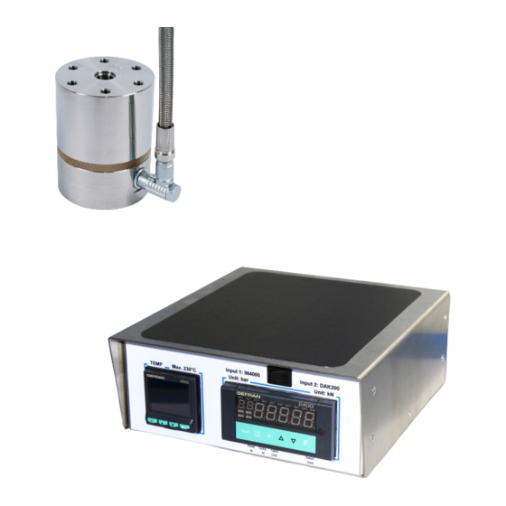
1.3. IN Sensor Main features • Nozzle pressure measurements up to 4000 bar with melt temperature up to 400° C. • Multi-shot measurements with different pressure levels at ≤230° C temperatures. • Simple magnetic installation without screws. • Possibility to use together with DAK nozzle contact force sensor. -
Page 8: Assessories
1.4. Assessories Nozzle adapter 10.8 Magnetic base Centering disc set 0.10 0.03 The set (F086992) contains Ø -0.05 / -0.15 1 piece 1 piece 1 piece Dimensions in mm Subject to technical modifications... -
Page 9: Indicator
1.5. Indicator Main features • Adjusting the heating tape temperature. • Injection nozzle pressure measurement. • Nozzle contact force measurement. • Power supply for IN Sensor, heating tape, DAK sensor. • RS232 output for serial communication between the indicator and a PC. 1.5.1. -
Page 10: Installation
Also make sure that the package cont- ains all accessories listed in the documentation. Warning! If even one of the above-mentioned requirements is not met, suspend installation and contact your Gefran dealer or Gefran Customer Service. 2.1. Changing the nozzle adapter The package includes a NA-IN-2 nozzle adapter. - Page 11 Example: Assembly drawing Heating band cable Sensor cable 3x M6x25 Nozzle adapter Heating band IN sensor Magnetic base 1x M8x20 3x M4x16 Subject to technical modifications...
-
Page 12: Connections
2.3. Connections Warning! Please remember that failing to follow the instructions below could lead to electrical safety and electromagnetic compatibility problems, as well as void the warranty. 2.3.1. General rules for connections All connections must be made with the indicator Never connect IN Sensor, DAK sensor, and heating turned off. -
Page 13: Operations
3. OPERATIONS 3.1. Measurement procedure The injection pressure measurement procedure, or the Multiple measurements can be made by repeating steps nozzle contact force, is as follows: 5 and 6 after removing the plastic injected. Application of the sensor to the moulding machine. Switching on the indicator. -
Page 14: Start Up
3.3. Start up Turn on the indicator. The instruments are fully operatio- rements with lower melt temperature, you cannot wait nal a few seconds after the indicator lights up. until the inside of the sensor has reached 230° C before proceeding with the measurements. -
Page 15: Measuring
3.6. Measuring To measure, a small amount of plastic is injected, which Inject as usual. The conical cavity in the nozzle adapter transmits the pressure to the measuring element. is filled with plastic and at the same time the injection nozzle pressure is measured, which is displayed in real time on the display. -
Page 16: Technical Specifications
4. TECHNICAL SPECIFICATIONS 4.1. IN Sensor SENSOR Strain gauge type Foil Maximum touch force 300 kN (@ 60 mm diameter) Measurement range 4000 bar Sensitivity 1.5 mV/V (nominal) MEASUREMENT Accuracy error < ± 0.5% FS Linearity error < 0.2% FS Repeatability error <... -
Page 17: Indicator
4.2. Indicator INSTRUMENTS Controller model Gefran 650 CONTROL HEATING TAPE Control interval 0...230 °C Meter Model Gefran 2400 MEASUREMENT Pressure/force selection By front switch PRESSURE / Measurement range Pressure: -4000...+4000 bar CONTACT FORCE Contact force: -200...+200 kN (with optional DAK sensor) -
Page 18: Order Codes
5. ORDER CODES 5.1. IN Sensor Order code: IN - XXXX X Heating tape model (F) Measurement range (A) 110 VAC 4000 bar 4000 230 VAC External IN Sensor diameter (B) 110 VAC + 230 VAC 60 mm (two heating tapes) Indicator (E) Connector and cable (C) Standard indicator... - Page 19 Notes: Subject to technical modifications...
- Page 20 SENSORMATE AG Steigweg 8 Tel. +41 (0)52 523 25 00 info@sensormate.ch CH-8355 Aadorf Fax +41 (0)52 364 32 72 www.sensormate.ch Schweiz...
Need help?
Do you have a question about the SENSORMATE IN-4000 SET and is the answer not in the manual?
Questions and answers