Table of Contents
Advertisement
Quick Links
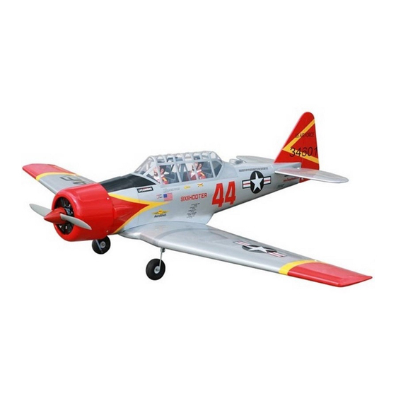
"Graphics and specifications may change without notice".
Specifications:
Wing span-------------------------------------------------- 62.9 in--------------------------------------- 159.8cm.
Wing area--------------------------------------------------620sq.in---------------------------------- 40 sq.dm.
Approximate flying weight-----------------------------6.2-7.7 lbs---------------------------2.8kg - 3.5kg.
Length------------------------------------------------------ 43.6in---------------------------------------- 110.8cm.
Recommended engine size--------------------------.40 - .52cu.in--------------------------------- 2-stroke.
ELECTRIC CONVERSION : OPTIONAL.
Recommended R/C --------------------------------------------- 4 channels with 6 servos.
Flying skill level ---------------------------------------------------- Advanced/Intermediate.
Kit features.
•
Ready-made—minimal assembly & finishing required.
•
Ready-covered—including decals, trim & covering.
•
Factory-installed pushrod.
•
Photo-illustrated step-by-step Assembly Manual.
ASSEMBLY MANUAL
------.72 - .82 cu.in-------------------------------- 4-stroke.
MS:110
Made in Vietnam.
Advertisement
Table of Contents

Subscribe to Our Youtube Channel
Related Manuals for Seagull Models AT-6 TEXAN


Summary of Contents for Seagull Models AT-6 TEXAN
- Page 1 MS:110 ASSEMBLY MANUAL “Graphics and specifications may change without notice”. Specifications: Wing span-------------------------------------------------- 62.9 in--------------------------------------- 159.8cm. Wing area--------------------------------------------------620sq.in---------------------------------- 40 sq.dm. Approximate flying weight-----------------------------6.2-7.7 lbs---------------------------2.8kg - 3.5kg. Length------------------------------------------------------ 43.6in---------------------------------------- 110.8cm. Recommended engine size--------------------------.40 - .52cu.in--------------------------------- 2-stroke. ------.72 - .82 cu.in-------------------------------- 4-stroke. ELECTRIC CONVERSION : OPTIONAL.
- Page 2 . Flying the AT-6 TEXAN is simply a joy. This instruction manual is designed to help you build a great flying aeroplane. Please read this manual thoroughly before starting assembly of your AT-6 TEXAN . Use the parts listing below to identify all parts.
-
Page 3: Hinging The Ailerons
Please trial fit all parts. Make sure you have the correct parts and that they fit and are aligned properly before gluing! This will ensure proper assembly as AT-6 TEXAN is made from Hinge. natural materials and minor adjust- ments may have to be made. The... -
Page 4: Hinging The Rudder
AT-6 TEXAN _ CODE SEA 110 Apply epoxy glue. C/A glue. 5) Turn the wing panel over and deflect the aileron in the opposite direction from the opposite side. Apply thin C/A glue to each hinge, making sure that the C/A penetrates into both the aileron and wing panel. - Page 5 www.seagullmodels.com Install the wing edge to the wing. AILERON CONTROL HORN Masking tape. Aileron control horn: See pictures below 2 sets. 3x35mm. CONTROL HORN M3 SCREW. Epoxy Epoxy ALUMINUM WASHER 18mm M3 LOCK NUT ALUMINUM WASHER...
-
Page 6: Rudder Control Horn
AT-6 TEXAN _ CODE SEA 110 Elevator control horn. RUDDER CONTROL HORN. Rudder control horn: ELEVATOR CONTROL HORN. Using the same techniques used aileron control horn. See picture below. Install the elevator control horn using the same method as with the aileron control horns. -
Page 7: Pushrod Installation
www.seagullmodels.com Remove covering. Rudder control horn. SERVO GEAR INSTALLATION. Metal connector. Electric wire. 25mm. Servo arm. Servo for retractable only. Wing bottom. PUSHROD INSTALLATION. Adjustable servo connector. Servo arm. loctile M3x25mm. secure. 3mm. 25mm. Remove covering. - Page 8 AT-6 TEXAN _ CODE SEA 110 Metal clevis. Pushrod. M3 lock. 2 x 6 mm. 3 x 25 mm.
- Page 9 www.seagullmodels.com Open Position Servo arm. Close Position 12 mm. Servo arm. Repeat procedure for other landing gear. Epoxy.
-
Page 10: Wing Assembly
AT-6 TEXAN _ CODE SEA 110 WING ASSEMBLY. epoxy. epoxy. -
Page 11: Engine Mount Installation
www.seagullmodels.com 2) Using a modeling knife, cut one length of silicon fuel line. Connect one end of the line to the weighted fuel pick up and the other end to the nylon pick up tube. 3) Carefully bend the second nylon tube up at a 45º... -
Page 12: Installing The Battery
AT-6 TEXAN _ CODE SEA 110 6) With the stopper assembly in place, Fuel tank. the weighted pickup should rest away from the rear of the tank and move freely inside the tank. The top of the vent tube should rest just below the top of the tank. -
Page 13: Mounting The Engine
www.seagullmodels.com MOUNTING THE ENGINE. Engine 4 stroke : 1.5 mm. 115mm. M3 x 25 mm. Trim and cut. M3 x 25 mm. Pushrod wire. M3 x 25 mm. - Page 14 AT-6 TEXAN _ CODE SEA 110 Engine 2 stroke : Trim and cut. M3 x10 mm. COWLING. Dummy M3 x 10 mm. Engine 1.5mm wire (needle valve). Electric Conversion (Ep Power) (OPTION). Trim and cut.
- Page 15 www.seagullmodels.com M4 x 15 mm. Diametrer = 5.2 mm. Epoxy.
- Page 16 AT-6 TEXAN _ CODE SEA 110 Epoxy. Epoxy. 115mm. Electric motor. Balsa block. Speed control. M3 x 15mm. Balsa block. Electric motor. Battery.
-
Page 17: Spinner Installation
www.seagullmodels.com INSTALLING THE AILERON SERVOS. SPINNER INSTALLATION. Small weight. Servos. Thread. Small weight. String. Small weight. Aileron Servo. String. Attach the string to the servo lead and carefully thread it through the wing. M2 x 12 mm. -
Page 18: Installing The Horizontal Stabilizer
AT-6 TEXAN _ CODE SEA 110 Elevator servo . Throttle servo arm. Rudder servo. INSTALLING THE HORIZONTAL STABILIZER. INSTALLING THE FUSELAGE SERVOS- Draw center line. SWITCH. Switch. Elevator. Throttle. When cutting through the covering to re- move it, cut with only enough pressure Rudder. -
Page 19: Installing The Vertical Stabilizer
www.seagullmodels.com INSTALLING THE VERTICAL STABILIZER. Trim and cut. Epoxy. Epoxy. Remove covering. Hinge slot. Pen. - Page 20 AT-6 TEXAN _ CODE SEA 110 Remove covering. C/A glue. Hinge. Epoxy. When cutting through the covering to re- move it, cut with only enough pressure to only cut through the covering itself. Cutting into the balsa structure may weaken it.
- Page 21 www.seagullmodels.com snap keeper. ELEVATOR - RUDDER PUSHROD INSTALLATION. Elevator control horn. M2 lock nut. Rudder control horn. Repeat the procedure for the other wing half. Rudder pushrod. M2 lock nut.
- Page 22 AT-6 TEXAN _ CODE SEA 110 Elevator and rudder pushrods assembly follow pictures below. 80mm. M2 clevis. M2 Lock nut. Attach to servo arm in fuselage. Wire keeper. Throttle. Elevator. Rudder. Fuel tank.
- Page 23 www.seagullmodels.com MOUNTING THE TAIL WHEEL. C/A glue. See picture below. C/A glue. M2 x 20 mm. 6mm. 6mm. M3 x 12 mm. INSTALLATION PILOT. 2pcs. 2pcs. M2 x 6 mm. Epoxy. Epoxy. 6mm. 2mm. 110mm.
- Page 24 AT-6 TEXAN _ CODE SEA 110 C/A glue. 55mm. 210mm. M2 x 6mm. 45mm. C/A glue. C/A glue.
-
Page 25: Installing The Receiver
www.seagullmodels.com Antenna. ATTACHMENT WING-FUSELAGE. Bolt the to fuselage.See pictures below. 90mm. C/A glue. Wing bolt. INSTALLING THE RECEIVER. BALANCING. 1) Plug the six servo leads and the switch lead into the receiver. Plug the battery pack 1) It is critical that your airplane be balanced lead into the switch also. -
Page 26: Control Throws
AT-6 TEXAN _ CODE SEA 110 CONTROL THROWS. INITIAL FLYING/SPORT FLYING Elevator: 10mm low rate 12mm high rate. Rudder: 15mm low rate 20mm high rate. Ailerons: 10mm low rate 12mm high rate. FLIGHT PREPARATION. D) Check the throttle. Moving the... -
Page 27: Preflight Check
2) Check every bolt and every glue joint and high rate settings. in the AT-6 TEXAN to ensure that every- 7) Check the receiver antenna. It should thing is tight and well bonded. be fully extended and not coiled up inside the fuselage.
Need help?
Do you have a question about the AT-6 TEXAN and is the answer not in the manual?
Questions and answers