Table of Contents
Advertisement
DU
DU
DU AL
DU
DU
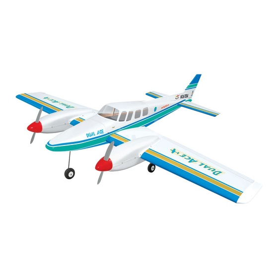
Hand-made Almost Ready to Fly R/C Model Aircraft
Specifications
Wingspan------------------------------------------ 70 in----------------------------- 177cm.
Wing area------------------------------------- 862sq.in---------------------- 55.6 sq.dm.
Approximate flying weight-------------------- 11lbs--------------------------------- 5kg.
Length---------------------------------------------- 59 in--------------------------- 149.5cm.
Recommended engine size-----------------.46 cu.in(2pcs)-------------- 2-stroke.
Radio System required 6 channels with 7 digital servos.
Flying skill level Intermediate/advanced.
Kit features.
•
Factory-installed pushrods.
•
Hardware pack with wheels, tank, undercarriage.
•
Photo-illustrated step-by-step Assembly Manual.
Made in Vietnam.
AL
AL A A A A A CE
AL
AL
ASSEMBLY MANUAL
CE
CE
CE
CE
Advertisement
Table of Contents

Related Manuals for Seagull Models DUAL ACE


Summary of Contents for Seagull Models DUAL ACE
- Page 1 AL A A A A A CE DU AL Hand-made Almost Ready to Fly R/C Model Aircraft ASSEMBLY MANUAL Specifications Wingspan------------------------------------------ 70 in----------------------------- 177cm. Wing area------------------------------------- 862sq.in---------------------- 55.6 sq.dm. Approximate flying weight-------------------- 11lbs--------------------------------- 5kg. Length---------------------------------------------- 59 in--------------------------- 149.5cm. Recommended engine size-----------------.46 cu.in(2pcs)-------------- 2-stroke. Radio System required 6 channels with 7 digital servos.
- Page 2 Manual. INTRODUCTION. Thank you for choosing the DUAL ACE ARTF by SEAGULL MODELS. The DUAL ACE was designed with the intermediate/advanced sport flyer in mind. It is a airplane which is easy to fly and quick to assemble. The airframe is conventionally built using balsa, plywood to make it stronger than the average ARTF , yet the design allows the aeroplane to be kept light.
- Page 3 This will ensure proper as- sembly as the DUAL ACE is made from natural materials and minor ad- justments may have to be made. The paint and plastic parts used in this kit are fuel proof.
-
Page 4: Hinging The Ailerons
DUAL ACE. Instruction Manual. ! 4)Deflect the aileron and completely HINGING THE AILERONS. saturate each hinge with thin C/A glue. The ailerons front surface should lightly contact the Note: The control surfaces, including the wing during this procedure. Ideally, when the ailerons, elevators, and rudder, are hinges are glued in place, a 1/64”... -
Page 5: Hinging The Elevators
DUAL ACE. Instruction Manual. ! 8) After both ailerons are securely hinged, firmly grasp the wing panel and aileron to make sure the hinges are securely glued and cannot be pulled out. Do this by carefully applying medium pressure, trying to separate the aileron from the wing panel. -
Page 6: Hinging The Rudder
DUAL ACE. Instruction Manual. ! 6) Using C/A remover/debonder and a paper towel, remove any excess C/A glue that may have accumulated on the horizontal stabilizer T-pins. or in the elevator hinge area. ! 7) Repeat this process with the other horizontal stabilizer panel, securely hinging the elevator in place. -
Page 7: Installing The Aileron Servos
DUAL ACE. Instruction Manual. ! 6) Using C/A remover/debonder and a paper towel, remove any excess C/A glue that may have accumulated on the fuselage or in the rudder hinge area. Note: Work the rudder left and right several times to “work in” the hinges and check for proper movement. -
Page 8: Installing The Aileron Linkage
DUAL ACE. Instruction Manual. Aileron electric. Plastic tape. Install the aileron servo tray into the servo mount. Repeat the procedure for orther wing haft. AILERON LINKAGE. INSTALLING THE AILERON LINKAGE. ! 1) Using a ruler & pen to draw a straight line as below picture. - Page 9 DUAL ACE. Instruction Manual. 3mmx30mm. 2mmx20mm. M3 lock nut. Clevis. Pen. Aileron torque rod. C/A glue attach. Control Horn. 3MM x 30mm. Mounting Screws. 2MM x 20mm. Cut. Mounting Plate. ! 4) Using a 1.5mm drill bit and the control horns as a guide, drill the mounting holes through the aileron halves.
-
Page 10: Installing The Stopper Assembly
DUAL ACE. Instruction Manual. ! 2) Using a modeling knife, cut one length Repeat the procedure for the other aileron servo. of silicon fuel line (not included) to 2-1/4” long. Connect one end of the line to the weighted fuel pickup and the other end to the nylon pick ATTACHMENT ENGINE MOUNTING up tube. - Page 11 DUAL ACE. Instruction Manual. ! 5) Test fit the stopper assembly into the tank. It may be necessary to remove some of Fuel tank. the flashing around the tank opening using a modeling knife. If flashing is present, make sure none falls into the tank.
-
Page 12: Mounting The Engine
DUAL ACE. Instruction Manual. ! 3) When you are satisfied with the align- ment, mark the locations of the engine mounting. 11.2cm. ! 4) Remove the engine. Using an drill bit, drill the mounting holes through the engine mount at the four locations marked. - Page 13 DUAL ACE. Instruction Manual. ! 2) While keeping the back edge of the Pushrod wire. nacelle flush with the marks, align the front of the nacelle with the crankshaft of the engine. The front of the nacelle should be positioned so the crankshaft is in nearly the middle of the nacelle opening.
-
Page 14: Installing The Spinner
DUAL ACE. Instruction Manual. Carburetor. Drill 1mm. 2mmX8mm. Repeat the procedure for the other nacelle. 2mmX8mm (10pcs). INSTALLING THE SPINNER. Plywood strap. Install the spinner backplate, propeller and spinner cone. The spinner cone is held in place using two 3mm x 12mm wood screws (spinner is not included). -
Page 15: Main Landing Gear Installation
DUAL ACE. Instruction Manual. ! 2) Insert the 90º bend of one main gear wire into the predrilled hole in one mounting slot. Landing gear wire. ! 3) The landing gear wire is held in place using two nylon landing gear straps and four 3mm x 10mm wood screws. -
Page 16: Nose Gear Installation
DUAL ACE. Instruction Manual. Installing the hard wood block. INSTALLING THE MAIN GEAR WHEELS. ! 1) Slide one wheel collar with 3mm x 6mm set screw onto each axle. Push the C/A glue. wheel collars on as far as they will go and tighten the set screws. -
Page 17: Installing The Cowling
DUAL ACE. Instruction Manual. 3mm X 10mm(4pcs). INSTALLING THE COWLING. Slide the fiberglass cowl over the engine HORIZONTAL STABILIZER. and line up the back edge of the cowl with the marks you made on the fuselage then trim and ! 1) Using a ruler and a pen, locate the cut. - Page 18 DUAL ACE. Instruction Manual. ! 6) Using a modeling knife, carefully re- move the covering that overlaps the stabilizer mounting platform sides in the fuselage. Re- move the covering from both the top and the bottom of the platform sides.
-
Page 19: Vertical Stabilizer Installation
DUAL ACE. Instruction Manual. VERTICAL STABILIZER INSTALLATION. Remove covering. When cutting through the covering to remove it, cut with only enough pressure ! 1) Slide the vertical stabilizer into the slot to only cut through the covering itself. Cut- of the fuselage. The bottom edge of the stabi-... - Page 20 DUAL ACE. Instruction Manual. Remove covering. ! 1) Locate the three nylon control horns, three nylon control horn backplates and six machine screws. ! 2) Position the elevator horn on the both side of elevator. The clevis attach- ment holes should be positioned over the hinge line.
-
Page 21: Installing The Fuselage Servos
DUAL ACE. Instruction Manual. ! 5) Position the rudder control horn on the left side of the airplane. Mount the control horn parallel with the horizontal stabilizer. Rudder control horn. Elevator control horn. INSTALLING THE FUSELAGE SERVOS. ELEVATOR-RUDDER PUSHROD INSTALLATION. -
Page 22: Installing The Receiver And Battery
DUAL ACE. Instruction Manual. Switch. Elevator. Steering Rudder. pushrod. Elevator. INSTALLING THE RECEIVER AND BATTERY. ! 1) Plug the seven servo leads and the switch lead into the receiver. Plug the battery pack lead into the switch also. INSTALLING THE SWITCH. - Page 23 DUAL ACE. Instruction Manual. Receiver. Wing bolts. Battery. ATTACHMENT WING-FUSELAGE. Attach the aluminium tube into fuselage. Insert two wing panels as pictures below: BALANCING. !1) It is critical that your airplane be bal- anced correctly. Improper balance will cause your plane to lose control and crash. The cen-...
-
Page 24: Control Throws
!2) Check every bolt and every glue joint Rudder: 1-1/4” right 1-1/4” left in the DUAL ACE to ensure that everything is tight and well bonded. Do not use the aerobatic settings for initial test flying or sport flying. !3) Double check the balance of the air- ! 4) By moving the position of the adjust- plane. - Page 25 !8) Properly balance the propeller. An out of balance propeller will cause excessive vi- bration which could lead to engine and/or air- frame failure. We wish you many safe and enjoyable flights with your DUAL ACE.
- Page 26 DUAL ACE. Instruction Manual. The pictures and parts shown above should be changed without notice.
Need help?
Do you have a question about the DUAL ACE and is the answer not in the manual?
Questions and answers