
Related Manuals for Midea CCM-270A/WS


Summary of Contents for Midea CCM-270A/WS
- Page 1 Commercial Air Conditioners Service Manual Touch Screen Centralized Controller 10.1-inch CCM-270A/WS...
- Page 2 CCM-270A/WS CONTENTS Part 1 CCM-270A/WS Introduction……………………………………..………………….…03 Part 2 CCM-270A/WS Installation & Commissioning………………………….…...17 Part 3 CCM-270A/WS Functions............…...47 Part 4 CCM-270A/WS Troubleshooting……….………………………….……….………123...
- Page 3 CCM-270A/WS...
-
Page 4: Table Of Contents
1 GENERAL ............................. 4 1.1 Safety Precautions ......................... 4 1.2 Attachments with the Box ......................6 2 CCM-270A/WS OVERVIEW ........................7 3 CCM-270A/WS HARDWARE DESCRIPTION .................... 8 3.1 Dimensions ........................... 8 3.2 Back Wiring ........................... 9 3.3 Port Diagram ..........................10 3.4 Energy Meter Introduction ...................... -
Page 5: General
CCM-270A/WS 1 General 1.1 Safety Precautions Read these safety precautions carefully before installing the CCM-270A/WS. After completing the installation, make sure that the power supply and CCM-270A/WS operate properly during the startup operation. General NOTICE Improper installation or attachment of equipment or accessories could result in electric shock, short-circuit, leaks, fire or other damage to the equipment. - Page 6 Reserve sufficient space for the installation, and leave adequate spacing between the device and surrounding community service network devices for heat dissipation. Make sure that the installation site is indoors and the CCM-270A/WS is installed at a height that is 50 cm above the ground. ...
-
Page 7: Attachments With The Box
CCM-270A/WS 1.2 Attachments with the Box The following below listed attachments are provided with the CCM-270A/WS package. CCM-270A/WS*1 User Manual *1 Mounting Board*1 3 port terminal with gap 5.08 mm*1 9 port terminal with gap 3.81 mm*2 4 port terminal with gap 3.81 mm*3... -
Page 8: Ccm-270A/Ws Overview
Option 3: We can use this gateway to connect with the IMMPRO software. IMMPRO is the latest network control software by Midea CAC and it can connect up to 10 CCM-270A/WS devices, with a capacity to control up to 3840 indoor units. -
Page 9: Ccm-270A/Ws Hardware Description
CCM-270A/WS 3 CCM-270A/WS Hardware Description 3.1 Dimensions 3.1.1 CCM-270A/WS Front and Side Views (Unit: mm) 3.1.2 Structural Dimensions of the embedded Junction Box (Unit: mm) Before digging an opening in the wall, it should be made sure that the opening is big enough to fit the embedded junction box. -
Page 10: Back Wiring
10.1 inch touch screen interface of the CCM-270A/WS. Important Points 1. The CCM-270A/WS must be installed at one end of the M-net communication bus. Do not install it in the middle of the bus. -
Page 11: Port Diagram
CCM-270A/WS 3.3 Port Diagram Port Description 24VAC 24VAC Interface X , XYE bus (COM1-6) Interface Y , XYE bus (COM1-6) Interface E , XYE bus (COM1-6) Reserved Reserved Reserved Reserved Reserved Reserved The Ethernet Interface connected to the network is used to access the device The USB 2.0 interface is used to export reports, import floor... -
Page 12: Energy Meter Introduction
To use the “ECS” function of CCM-270A/WS, an energy meter should be connected to the outdoor units to monitor the energy consumed which thereby can be sent to the CCM-270A/WS and hence it can be used to bill the tenants of indoor units according to the usage of indoor units done by them. -
Page 13: Ccm-270A/Ws Specifications
0.85 Kg Weight Black Device Color 4.1 CCM-270A/WS Numeric Analysis Here in this section, we have described the number of units that can be controlled by one CCM-270A/WS device. The numbers show up as follows: Parameter Number Number of ports... -
Page 14: Comparison With Immp-M
IMMPRO software. It is important to analyze what are the various difference between them. The obvious advantage is that in CCM-270A/WS, a 10.1 inch touch screen is present which makes it able to be used independently as well as with IMMPRO. -
Page 15: Ccm-270A/Ws Network
LAN can be made by the LAN cable or router depending up on the specific project configurations. Each XYE port of the CCM-270A/WS can connect up to 64 indoor units or up to 8 refrigerant systems. There is a support for USB 2.0 also available in the CCM-270A/WS device which can be used to upload and download certain documents outputted... -
Page 16: Supported Models
2. Communication line to the M-Net port must be connected to the master outdoor unit. 3. The CCM-270A/WS is a gateway device based on web technologies which has nothing to do with the operating systems of computer or other similar devices. Once you are connected to the network, you can use the browser on the system platform to view the website of the centralized controller gateway anytime, anywhere. - Page 17 CCM-270A/WS 201807...
- Page 18 1.14 Set the Normal User Account ..................... 40 1.15 Energy Meter Installation ......................41 2 FIRST TIME INSTALLATION CHECKLIST ....................44 2.1 Flow Chart for CCM-270A/WS Touch Screen Centralized Controller ..........44 2.2 Flow Chart for CCM-270A/WS Computer Website ................ 45 201807...
-
Page 19: Installation And Commissioning
1 Installation and Commissioning For Touch Screen: In this section, it is explained about how to install the hardware of CCM-270A/WS in the wall and also what are the various connections that are required to be done between the centralized controller and the VRF units to use the centralized controller to control the units. - Page 20 CCM-270A/WS 1.1.2 Install the Metal Parts Make sure that the hooks of the metal parts face upwards. Use 4 screws ④ provided as accessories to secure on the installation base. Note: Make sure that appropriate force is exerted to secure the metal parts with the screws. Excessive force may lead to deformation of the four screw holes for the metal parts, which would make it hard to mount the metal mounting board.
- Page 21 CCM-270A/WS 1.1.3 Install CCM-270A/WS Once the connections are done, place the main unit vertically into the installation base. A magnetic force would attract the controller. Exert downward force to mount the controller on the metal part. There are hooks which are attached on the installation base and the controller can be mounted on these hooks.
-
Page 22: Topology Modes
1.2.1 Auto Topology Mode This is the basic mode of connection while using the CCM-270A/WS centralized controller. This type of topology does not require the user to upload any topology file. The user simply needs to connect the units with the controller and on searching the information about the air conditioning units through the “Install”... - Page 23 In case of using the manual topology mode, we need to supply the complete information about the connections between the ODU and IDU to the CCM-270A/WS in the form of a topology document. This document can be uploaded into the controller with the help of the USB disk.
- Page 24 The imported system bus exceeds limit. Please CCM-270A/WS port is not within 0-5. confirm it before search The imported refrigerant system exceeds limit. Refrigerant system address is not within 0-7.
-
Page 25: Flow Chart
Before we discuss in detail about the various steps that need to be followed for successful installation and commissioning of CCM-270A/WS device, below is listed a flow chart of all the events that need to be followed. In this flow chart, is given a sequence of actions that need to be followed to successfully finish the installation and commissioning of the CCM-270A/WS gateway device both for touch screen and computer website. - Page 26 CCM-270A/WS 1.3.2 For Computer Website The following flow chart describes the installation steps required while we need to use only the computer website of CCM-270A/WS. Connections between ODU &IDU Power cable connection LAN/Network connections Pre Installation(IP) Settings Set the ODU to auto addressing mode & adjust ENC4 switch* Open the website;...
-
Page 27: Connections Between Odu And Idu
1.5 Power Cable Connections We need to make sure that the power supply has been provided to the CCM-270A/WS. If the power supply is not there we cannot perform the further operations such as searching the units. The power cable is not provided as a standard accessory with the box. - Page 28 CCM-270A/WS After some time, the touch screen will land to the user interface. 201807...
-
Page 29: Network Connections
CCM-270A/WS For Power Indication: Look at the back side of the CCM-270A/WS gateway device and check whether the red colored system lightings are blinking inside the back panel of the device. If the LEDs are blinking, it means power is being received by the CCM-270A/WS gateway device. - Page 30 CCM-270A/WS Important Points: 1. The default Ethernet IP of the CCM-270A/WS is 192.168.100.40:8000 2. When more than one gateway devices are connected to LAN in a project, configure different IPs for the gateways 3. The centralized controller obtains static IP.
-
Page 31: Pre Installation Settings
1. Configure Single IP Address: For the CCM-270A/WS gateway, to connect with the computer it needs to be verified that it is in the same IP segment as the computer. To make this happen, we need to make sure that proper IP Configuration settings have been done. Following are the steps that need to be followed to complete the IP settings: Default IP of CCM-270A/WS is 192.168.100.40:8000;... - Page 32 CCM-270A/WS (Dialog box 1) (Dialog box 2) (Dialog box 3) (Dialog box 4) (Dialog box 5) 201807...
- Page 33 CCM-270A/WS After you finish this IP configuration, try to visit the website of the CCM-270A/WS by typing the IP address (192.168.100.40:8000) in any of the web browser (preferably Google Chrome version 52.0 or above) if the website of CCM-270A/WS is getting opened, it means that the IP configuration setting is successful.
- Page 34 CCM-270A/WS Enter "ipconfig" above to display the local dynamic IP address. Use this address as the IP address in TCP/IP properties to complete the static IP address configuration. Consult the local network administrator for details. Once the static IP address has been configured, open the Internet Protocol TCP/IP Settings page again. Select "Advanced..." to go to the TCP/IP advanced settings page, as shown in the figure below.
- Page 35 3. Local LAN Access: As long as the computer or other similar equipment in the LAN is in the same segment as the CCM-270A/WS, you can use the address bar in the browser on its operating system to enter the address to link to the webpage of the CCM-270A/WS (for example: http://192.168.100.40:8000) to directly access, operate and control the air conditioners.
-
Page 36: Auto Addressing Mode
Let’s discuss the settings for this switch. In case, there is only one system in each port of CCM-270A/WS, there is no need to set the ENC4 switch for this situation. We can keep the network address of the outdoor unit as 0 as the outdoor units would be distinguished from each other on the basis of settings of ENC1 switch. -
Page 37: Booting Up Of Ccm-270A/Ws
3. If the equipment does not get started after some time, you need to check the red colored system lightings inside the back panel of the CCM-270A/WS are blinking or not. If not, it means that the equipment is not energized. Check the power supply and wiring. -
Page 38: Login
CCM-270A/WS 1.11 Login For Touch Screen: Once the boot up is finished, the controller would reach to the user interface. Here, we need to Login with the administrator account. The default username and password for administrator account are as follows:... -
Page 39: Install The Idus
For Computer website: This step is same for both touch screen as well as computer website. After successful login, we need to install the IDUs. We will reach the homepage of CCM-270A/WS. Click on the Install Tab to enter the Installation page On the installation page, select the required installation mode that is Auto Topology or Manual Topology (written as Auto topo and Manual topo) respectively. -
Page 40: Checking The Installation Results
CCM-270A/WS Important Points: 1. Refer to the Manual Topology document format and example which is discussed above. 2. Do not operate the gateway during this time to prevent topo failure. 3. It takes about 7 minutes to complete the Install IDUs process. The user needs to wait patiently. -
Page 41: Set The Normal User Account
In the Setting tab of the CCM-270A/WS, we need to select the “Account” menu and if you are logged in with administrator account, clicking on “Add” will add a normal user account. -
Page 42: Energy Meter Installation
1.15 Energy Meter Installation To use the “ECS” function of the CCM-270A/WS, the energy meter should be connected to the outdoor units to monitor the energy consumed by the outdoor units which can be sent to the software and hence it can be used by the software to calculate the energy consumed by various tenants. - Page 43 100m. Communication cable is isolated to high voltage. Important points: (1) The power meter is customized by Midea, it has been set to the percentage of 30:1, and if it is bought from the market, it cannot be used normally.
- Page 44 CCM-270A/WS Face Back 201807...
-
Page 45: First Time Installation Checklist
2 First Time Installation Checklist 2.1 Flow Chart for CCM-270A/WS Touch Screen Centralized Controller Below is a flow chart of the check points that need to be kept in mind while installing the CCM-270A/WS centralized controller for first time. Process... -
Page 46: Flow Chart For Ccm-270A/Ws Computer Website
CCM-270A/WS 2.2 Flow Chart for CCM-270A/WS Computer Website Below is a flow chart of check points that need to be kept in mind while installing the CCM-270A/WS for computer website. Process Check Point Connect the IDU and ODU Refer to the IDU and ODU respective installation manuals. - Page 47 CCM-270A/WS Part 3 Functions 1 START UP ............................49 2 LOGIN ..............................50 3 HOME PAGE ............................51 3.1 Overview of Indoor Units Running Status ..................51 3.2 Function Menu ..........................52 3.3 Special Menu ..........................52 3.4 Date and Time ..........................52 3.5 Schedule for Today ........................
- Page 48 CCM-270A/WS 7 ECO..............................85 8 INSTALL .............................. 90 8.1 Edit ............................. 94 8.2 Group ............................95 8.3 Edit Map ............................99 9 SETTING ............................104 9.1 Account ............................105 9.2 Date and Time Settings .......................108 9.3 Holiday Settings ..........................110 9.4 Network Settings ........................111 9.5 General Settings .........................112...
-
Page 49: Start Up
(Boot Screen) For Computer Website: The default IP of CCM-270A/WS is 192.168.100.40:8000. The user just needs to put this in the website column of the web browser (preferably Google Chrome version 52.0 or above) and the login page will open up:... -
Page 50: Login
If correct IP settings have been done (the details about the IP settings have been discussed in Installation & Commissioning part of this manual), the website of CCM-270A/WS can be opened by the browser available on the computer system. Item... -
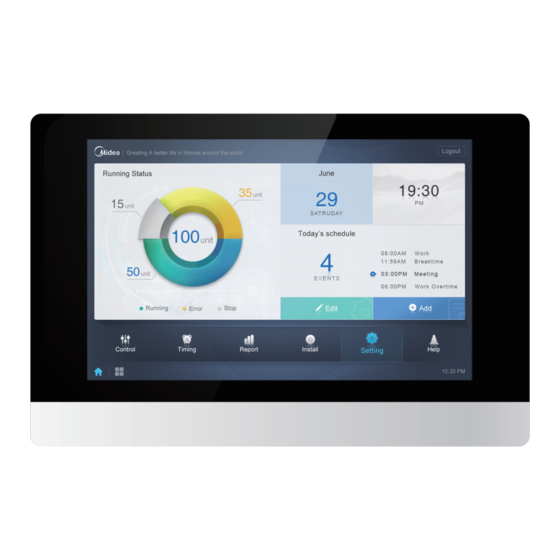
Page 51: Home Page
CCM-270A/WS 3 Home Page For Touch Screen: Once the login is successful, the user gets on this page For Computer Website: Once the login is successful, the user gets on this page The various components of this page have been described as under: 3.1 Overview of Indoor Units Running Status... -
Page 52: Function Menu
CCM-270A/WS 3.2 Function Menu In this tab, navigation for all the functions is provided. It is present at the bottom of the homepage. 3.3 Special Menu Item Description Back to home Operating History 3.4 Date and Time The date and time for the particular day is displayed on the right side of the interface. The date is also displayed on the bottom right side of the home page. -
Page 53: Account
CCM-270A/WS 3.6 Account On the top right corner, is also shown the current account being used to login into the CCM-270A/WS. You can logout from here to change the account 201807... -
Page 54: Control
CCM-270A/WS 4 Control Select an option on the left side interface of this page to view the corresponding indoor units. 4.1 Icons Description 4.1.1 General Icons View Scheme These 3 icons on the extreme top left of the “Control” interface screen are responsible to change the viewing scheme that is to view as per group/system/map. - Page 55 CCM-270A/WS Sorting Display These keys are present on the top right side of the interface. Function Inactive Active Sort by mode: Auto, Cool, Heat, Dry, Fan, Off, Error, Offline Sort by name Navigation Keys These keys are present on the bottom left side of the Interface...
- Page 56 CCM-270A/WS 4.1.2 Indoor Units Icon Description Description The colors here represent the operating modes. The details about the colors are provided in the table of Mode Description. Indicators (in order from left to right): error*, schedule, lock, swing. Icon is white when active, such as the lock indicator in the above figure.
- Page 57 CCM-270A/WS Mode Description Mode Color & Icon Icon Grey Off, Error, Offline Dark Blue Auto Light Blue Cool Heat Green Orange 201807...
- Page 58 CCM-270A/WS Indoor Unit Type Description Code Of IDU Model Description Picture Old IDU 4-Way Cassette(4-WAY) Wall Mounted Medium Static Pressure Duct (M-Duct) Low Static Pressure Duct(L-Duct) Air Handling Unit(AHU) High Static Pressure Duct(H-Duct) Compact 4- Way Cassette(COMPACT) Ceiling & Floor...
-
Page 59: Indoor Unit View- Group
CCM-270A/WS 4.2 Indoor Unit View- Group This function shows the various indoor units which are present in the groups created by the user. The group creation is available in the “Install” tab functions. Along with the created groups, also is present a default “Ungrouped” where all the indoor units which have not been assigned to any group are present. - Page 60 CCM-270A/WS Top Menu Buttons: Tap "All" to select all the indoor units in this page. Tap "Cancel" to cancel the selection for all indoor units; Tap "Control" and you will get the following control window: The icon shown on the below of the screen would also take you to the control menu.
- Page 61 CCM-270A/WS Non-Auto Mode Display Auto Mode Display Icon Description It is to switch ON or OFF the indoor unit. It is to select the operating mode for the indoor unit. It is to set the temperature for the indoor unit, two set points are available in the Auto Mode and only one set point is available in Non- Auto Mode.
-
Page 62: Indoor Unit View - System
CCM-270A/WS 4.3 Indoor Unit View – System This is also similar to “Group Navigation”, except that the system (instead of the groups) is on the left. System name is default and cannot be changed. In this type, the indoor units are displayed according to the systems from which they come. - Page 63 “Map” tab of the “Install” menu. The user needs to upload the map (picture) into CCM-270A/WS touch screen controller using a USB disk which can be connected to the US port of the touch screen centralized controller.
-
Page 64: Schedule
CCM-270A/WS 5 Schedule For Touch Screen & Computer Website: This function is same both for the computer website and touch screen controller. Once we have tapped the “Schedule” icon at the “Home Page” to go to the function module, the following display would be there. -
Page 65: Schedule View Types
CCM-270A/WS 5.1 Schedule View Types 5.1.1 Calendar View The calendar view is used to display the schedules present according to the various dates. The user can click on any of the dates and the schedule related to that date would be displayed. For today, it will show only the schedule which is waiting to be implemented, already implemented schedule will not be shown. - Page 66 CCM-270A/WS Schedule View (Right Side) The schedule page only shows scheduled tasks that have not been performed for the selected date (arranged in the order of implementation time). The displayed information is as follows 1. Time 2. Schedule name 3. Details of the executed command (“On/Off”, “Mode”, “Temperature”, “Set Point”, “Fan Speed”).
- Page 67 CCM-270A/WS Function Tap the left icon to go to the schedule editor. Using this, the current schedule which has been selected can be edited. Tap the right icon to delete the selected schedule. The schedules are arranged in order of their time of creation. Tap to select the schedule you need. Selected schedule has a blue background color.
- Page 68 CCM-270A/WS 5.1.3 Device View Tap the third icon to go to the device view. The page is divided into three sections. 1. Group List: This makes it easy to locate the device quickly. Tap "+" to expand the group, and "-" to minimize the group.
-
Page 69: Add Schedule
CCM-270A/WS 5.2 Add Schedule This interface is common for all kind of schedule views: Calendar, Device and Plan. It is used to add new schedules. Function The device list displays all the devices related to the schedule. Tap on “Select IDU” to add more devices to the current schedule. - Page 70 CCM-270A/WS 5.2.1 Add Device This interface would be shown up on clicking on the “Select IDU” tab on the previous page. The user can simply click on the devices being shown in the right side of the display and after clicking on “Add”, the following devices would be added to the corresponding schedule.
- Page 71 CCM-270A/WS 5.2.2 Date settings Function Tap the input box to enter a name for the schedule. Maximum length is 80 English characters (40 Chinese characters). Note that system is unable to save the name if it contains the following symbols: ([`~!#$^&*()=|{}':;,\.<>/…?~!¥...
- Page 72 CCM-270A/WS 2. HRV (Heat Recovery Ventilator) has 4 operating modes: Heat Exchange, Bypass, Discharge and Fan. You cannot change the temperature set point in all four modes and the fan speed is Speed 7 + Auto. 201807...
- Page 73 CCM-270A/WS 3. The Auto mode supporting units have five types of operating modes: Auto, Cool, Heat, Dry, and Fan. In the Auto mode, "C" is the cooling temperature, and "H" is the heating temperature. In the Cool, Heat and Dry modes, "C" is the temperature set point.
- Page 74 CCM-270A/WS Icon Description This is used to select the type of indoor unit. Four options are available: It is to set the time for implementation of the corresponding schedule command. It is to set the set point temperatures for the corresponding indoor unit, it can be dual set points in case of Auto mode whereas in other case it will be single set point temperature.
- Page 75 CCM-270A/WS Important Points: 1. Clicking will copy the latest added schedule command from the list shown in bottom right. Please note that the 23:59 timing command cannot be copied. 2. For the timings that have been saved, tap to edit again, and to delete 3.
-
Page 76: Report
CCM-270A/WS 6 Report For Touch Screen: The default output for the export results can be the USB disk or email For Computer Website: The default download folder for computer website is only the default download folder for the web browser. -
Page 77: Operating Duration
CCM-270A/WS (After Activation) 6.1 Operating Duration It can be used to view the total operation duration of the indoor units for a specified time period. Note: You can query the time and energy statistics reports only after the operating electricity file has been generated. The electricity file is generated at every point. - Page 78 CCM-270A/WS 6.1.2 Procedure 1. Tap the selected device to go to the device selections page. 2. Details of the device page are as follows: Function Devices waiting to be selected are displayed in the rightmost area, and these are the devices that have not been added to the selected subgroup.
-
Page 79: Running Record
CCM-270A/WS 3. Perform the time selection, once the device has been added. Function Tap in this area (except the blue calendar icon) to activate the calendar. Tap any number to select the date. Selected date in the box has a light blue background, otherwise today's date is selected. -
Page 80: Energy Statistics
CCM-270A/WS 6.3 Energy Statistics The method to query energy statistics is similar to that for the previous two functions. However, for the first two modes, you can only add up to three devices to search. There are no restrictions in the table mode. Use at the top right corner to select the different modes. - Page 81 CCM-270A/WS (Histogram) For histograms and line graphs, you can only select 3 objects and select either IDU or refrigerant system. The selected time for graphs and lists is based on the month (effective graph is based on day). There are only two options in total energy: total energy and operating energy.
-
Page 82: Log
CCM-270A/WS 6.4 Log at the bottom left corner of the Home page to go to the log page. Certain operations of the software are recorded in logs, and these are classified into the following categories: General control command ECO control command... -
Page 83: Export Function
CCM-270A/WS 6.5 Export Function For “Operating Duration”, “Running Record” and “Energy Statistics” reports, there are functions to export the queries records to “.csv” files (except for histograms and graphs). The contents of the exported files are consistent with the current results of the queries. - Page 84 Note: * The email settings in the “Setting” tab needs to be performed by professional people for successful using of the Email function of CCM-270A/WS controller. This function is not available while using the computer website.
-
Page 85: Eco
CCM-270A/WS 7 Eco For Touch Screen & Computer Website: This function is similar for both. This function is basically present to set some limitations on the use of indoor and outdoor units. Using this tab, some of the functions both of the IDU and ODU can be restricted or their range can be limited. - Page 86 CCM-270A/WS The description of these control commands is as follows: Control command Description The options available are “--”*, “Unlimited” which means no limitation, “ON” the unit will remain on, “OFF” the unit will always remain OFF. The options available are “--”*, “Unlimited” which means no limitation, the other options are to set the exact value of cooling set point temperature.
- Page 87 Note: Certain outdoor units may not support one or more lock commands shown above. The CCM-270A/WS can send any lock command to the outdoor unit. If the outdoor unit does not support the lock command, the outdoor unit will process the command based on its own logic.
- Page 88 CCM-270A/WS Silence Mode Command The user needs to set the ENC5 switch to F value in order to use this setting from the CCM-270A/WS touch screen/computer website. CCM-270A/WS Setting Description Option Night silent time is 6h/10h (default) Night silent time is 6h/12h...
- Page 89 Note: No special settings are required to be done on the outdoor unit side, in order to be able to use the “Auto Energy Saving” mode from touch screen/computer website. CCM-270A/WS Setting Description Option Exit Auto Energy Saving Mode Auto Energy Saving Enter Auto Energy Saving Mode This setting is to enable or disable the smart Energy Saving Mode for Midea VRF. 201807...
-
Page 90: Install
8 Install Under this function, we can install the units into the CCM-270A/WS. There are two options available for installing the units that is the “Auto topo” and “Manual topo”. The difference between the two topologies have been discussed already in the Installation &... - Page 91 CCM-270A/WS Auto Topology: Under this topology mode, the user does not require doing any special settings for the units. He just needs to connect the units normally and do the IP settings as has been discussed in the Installation Part of this manual. After clicking on the “Auto Topo”...
- Page 92 In case of manual topology, the user needs to insert a manual topology document giving details about the system to the CCM-270A/WS. The details on how to write the manual topology document have been discussed in detail in the “Installation & Commissioning” part of this manual.
- Page 93 CCM-270A/WS Once the installing has been finished both in the case of “Auto topo” or “Manual topo”, the user needs to click on the “Save” button on the bottom right to store the installation results 201807...
-
Page 94: Edit
CCM-270A/WS 8.1 Edit Clicking on the column for “Name”, “Fan” and “EH” allows the user to edit their values. The name of the unit can be changed for easy identification by the user. The option for “Fan” and “EH” are to set the rated value of power consumed by the fan or electric heater of that particular indoor unit. -
Page 95: Group
CCM-270A/WS 8.2 Group at the lower-left corner to go to the group editor from the installation page. Description This shows the groups already created by the user: clicking on “+” will show the subgroups present under that group. Similarly clicking on “-” will hide the groups present in that particular group. Clicking on the name of the group will show the indoor units present in that group in 2. - Page 96 8.2.1 Create, Edit and Delete Group at the bottom left corner to go to the pages to create, edit and delete group. The CCM-270A/WS supports three group levels. The three levels of the groups have been created with the notion that suppose there is a building, it will be a Level 1 group, each floor of building then becomes the Level 2 group and each room on the floor then would be the Level 3 group.
- Page 97 CCM-270A/WS Edit, Delete Group When a group is selected, you will see the edit and delete function keys for the selected group. Tap the edit icon to go to the group name editor Tap “Delete” to delete the group. Note: Make sure you tap “Save” at the bottom of the page to save all create and edit operations. Otherwise, the changes will be discarded.
- Page 98 CCM-270A/WS In the middle, we can select the indoor unit to be deleted, tap to remove the indoor unit from the corresponding group. Once the edits to the indoor units in the group have been completed, tap (at the bottom of page) to save the changes.
-
Page 99: Edit Map
CCM-270A/WS 8.3 Edit Map For Touch Screen: This function is only available for the touch screen. Once you are in the “Install” menu, tap on “Map” to enter the map editor to edit the map and the devices in it. - Page 100 CCM-270A/WS The method to add groups in the “Map” is also same as that of “Group” function. Once the edits have been completed, tap to go to the map editor to edit the map as well as add a position to the indoor units.
- Page 101 CCM-270A/WS The following markings have been described as under: 1. Group Selection Area. Tap “Edit” to edit the map in the selected group. Groups with subgroups are marked with an icon on the left of the group. Tap , if you want to expand the group and see the subgroups present inside it. Tap , if the group is already expanded and you want to roll back the expansion.
- Page 102 CCM-270A/WS 6. It shows the devices that are not in the map. Default is to sort by name. Use 7 to switch the sort menu by mode. Tap to select the device ; tap again to deselect the device. Add up to seven devices each time.
- Page 103 CCM-270A/WS 10. This button is to save all the operations. 11. This button is to cancel all the operations. 201807...
-
Page 104: Setting
CCM-270A/WS 9 Setting in the main page to go to the settings page. Default is the “Account” page. Description This shows the list of available functions in the settings page. Tap to jump to the corresponding tab. This shows the details of different tabs. -
Page 105: Account
CCM-270A/WS 9.1 Account For Touch Screen & Computer Website: This function is same for both. Administrator (Administrator Page) The administrator account has permissions to add or remove accounts along with that administrator’s account has the permissions to change the passwords of other accounts. This account is basically for the engineers or service personnel. - Page 106 CCM-270A/WS for the respective account. Disable the Anonymity Account Clicking on disable would disable the “Anonymity” account. Delete users 201807...
- Page 107 CCM-270A/WS Clicking on the small cross on the top right of the account would open a dialog box promptly asking to delete the user account. Here, in this example we are trying to delete the “normal” account. Clicking on “OK” would delete that particular account.
-
Page 108: Date And Time Settings
This is a toggle switch used to switch between the 12 hour and 24hour display of time. It shows the current date in the form of a calendar. It shows the analog as well as a digital clock showing the current time for the CCM-270A/WS. 201807... - Page 109 CCM-270A/WS Edit Mode: (Edit Mode) Description It is used to switch between 24-hour clock and 12-hour clock system. You can adjust the system timing system in both edit and non-edit modes. When the slider is white and inactive, slide to the left, and the slider becomes blue and active, and the system switches to the 24-hour clock system.
-
Page 110: Holiday Settings
CCM-270A/WS 9.3 Holiday Settings For Touch Screen & Computer Website: This function is same for both. Function Displays the current year and month. Tap to change the month. Shortcut to return to the current system date. Tap to activate it immediately. -
Page 111: Network Settings
9.4 Network Settings In this page you can change the IP of the CCM-270A/WS. Just click on the IP written in this page and you can edit the IP according to your will and requirement. Click on “Save” saves the changed IP settings. -
Page 112: General Settings
CCM-270A/WS 9.5 General Settings Function This tab is used to adjust the brightness of the touch screen. This option has no meaning for computer website Changes the display language. Tap to activate the drop-down box and tap further to select the desired language.* Adjusts the group's display mode. -
Page 113: Mail Settings
CCM-270A/WS 9.6 Mail Settings For Touch Screen: This function is only available with the Touch screen of centralized controller CCM-270A/WS. The following is the interface for the “Mail” tab in “Setting” menu. The following has been described as under. 1. Displays the configuration of the current sender. Tap to configure and edit the sender. - Page 114 CCM-270A/WS Displays all the information about the recipient. Tap to edit. Fill in the corresponding details. Tap “OK” to save and exit. Tap “Cancel” to cancel all the operations and exit. If the mailbox format is wrong, there would be corresponding error message to fill those details. Tap “Cancel” to cancel all the operations and exit.
- Page 115 Tap “OK” to save and exit. Tap “Cancel” to cancel all the operations and exit. Tap “Delete” again to exit the delete mode. For Computer Website: This function is not available for computer website of CCM-270A/WS 201807...
-
Page 116: Advanced Settings
Reboot: On adjusting the slider, the following below shown dialog box will get opened. This function is to reboot the device Factory data Reset: This button is to restore the factory settings in CCM-270A/WS. On adjusting the slider, the following below shown dialog box will get opened. - Page 117 CCM-270A/WS Machine Code: This setting is to activate the “ECS” function for the CCM-270A/WS device. On clicking the slider, the following below shown dialog box would get opened. The subsequent QR code needs to be sent to Midea Technical Support Engineer for the activation of the function.
-
Page 118: Public Device
CCM-270A/WS 9.8 Public Device For Touch Screen & Computer Website: This function is same for both. Function It displays the group option. All the devices in the groups (including subgroups) are displayed on the right, and the groups are arranged based on the time of creation. -
Page 119: Ecs Settings
9.9 ECS Settings For Touch Screen & Computer Website: This function is same for both. This kind of setting is related to the energy consumption statistics function of the CCM-270A/WS. The various functions under this have been described as below: Function It is to set the price of one unit for the electricity consumption. -
Page 120: Help
For Touch Screen & Computer Website: This function is same both for the touch screen and computer website. on the main page to go to the “Help” module of CCM-270A/WS. Under this section, you can find the list of error codes both for the IDU and ODU which can be very helpful for the users. -
Page 121: Comparison Between Touch Screen And Computer Website Functions
CCM-270A/WS 11 Comparison between Touch screen and Computer Website functions Parameter Touch Screen Website Map View Available Not Available Mail Function Available Not Available Map View Available Not Available Update Function Available Not Available Default export Location USB Disk / Email... - Page 122 CCM-270A/WS 201807...
- Page 123 1.9 Number of indoor units is less than the number of indoor units connected .........125 1.10 Failed to find the required maps, while importing maps from USB disk ........125 1.11 CCM-270A/WS does not support other languages ..............125 2 APPENDIX ............................126 2.1 Appendix 1: Software Use Precautions ..................126...
-
Page 124: Basic Troubleshooting
1.1 Equipment cannot be started Solution: First of all, check whether the red coloured system lightings inside the back panel of the CCM-270A/WS are blinking or not. If not blinking, it indicates that the power is not getting supplied. Check whether the power cable is properly connected or not. -
Page 125: Failed To Upgrade The Equipment
Solution: For the new units, certain wired controllers support the access of multiple IDUs where these IDUs will then form a “wired controller group”. In CCM-270A/WS, these IDUs will be treated as a single virtual IDU and in the icon view in the “Control”... -
Page 126: Appendix
For the new units, certain wired controllers support the access of multiple IDUs where these IDUs will then form a "wired controller group". In CCM-270A/WS, these IDUs will be treated as a single virtual IDU, and in the icon view in "Control" the wired controller group of IDUs will have its own icon. -
Page 127: Appendix 3: Export File Samples
CCM-270A/WS 2.3 Appendix 3: Export File Samples In this section, we have listed some of the samples of the reports that would be outputted by the CCM-270A/WS system under various circumstances. 2.3.1 Energy Statistics Excel The energy document outputted from CCM-270A/WS system will look as follows: Note: The energy cost depends up on the cost per unit set in the Setting part. - Page 128 CCM-270A/WS 2.3.2 Operating Duration Below is a sample of the excel document outputted by clicking the Operating Duration Tab in the Report function of CCM-270A/WS. 201807...
- Page 129 CCM-270A/WS 2.3.3 Running Record Below is a sample document for the excel file exported from the running record tab of the Report function. Note: The CCM-270A/WS can only store the data for last 12 months. 201807...
-
Page 130: Appendix 4 : Introduction To Immpro System
). The IMMPRO software communicates with IMMP-M or CCM-270A/WS via the network to control and manage the VRF units. The following figure shows the composition of the IMMPRO system: The IMMPRO system can control up to 3840 indoor units with just one computer. - Page 131 CCM-270A/WS 201807...
- Page 132 Commercial Air Conditioner Division Midea Group Add.: Midea Headquarters Building, 6 Midea Avenue, Shunde, Foshan, Guangdong, China Postal code: 528311 Tel: +86-757-26338346 Fax: +86-757-22390205 cac.midea.com global.midea.com Note: Product speci cations change from time to time as product improvements and developments are released and may vary from those in this document.
Need help?
Do you have a question about the CCM-270A/WS and is the answer not in the manual?
Questions and answers