
Related Manuals for Midea KSACN0401AAA


Summary of Contents for Midea KSACN0401AAA
- Page 1 Wired Remote Controller 7 Day Programmable Thermostat Ductless Systems KSACN0401AAA KSACN0501AAA OWNER'S MANUAL...
-
Page 2: Table Of Contents
TABLE OF CONTENTS PAGE SAFETY CONSIDERATIONS ....... WIRED CONTROLLER FEATURES AND FUNCTIONS . -
Page 3: Safety Considerations
SAFETY CONSIDERATIONS Installing, starting up, and servicing air−conditioning equipment can be hazardous due to system pressures, electrical components, and equipment location (roofs, elevated structures, etc.). Only trained, qualified installers and service mechanics should install, start−up, and service this equipment. Untrained personnel can perform basic maintenance functions such as cleaning coils. - Page 4 CAUTION ELECTRICAL SHOCK HAZARD Failure to follow this warning could result in personal injury or death. Before beginning any modification or installation of this kit, ensure the main electrical disconnect is in the OFF position. Ensure power is disconnected to the fan coil unit. On some systems both the fan coil and the outdoor unit may be on the same disconnect.
-
Page 5: Wired Controller Features And Functions
WIRED CONTROLLER FEATURES AND FUNCTIONS Features: LCD display Malfunction code display − displays the error code (helpful for servicing) 4−way wire layout design Room temperature display Weekly schedule Functions: Mode: choose Auto−Cool−Dry−Heat−Fan Fan speed: Auto−Low−Med−High Swing (on some models) Timer ON/OFF Temp setting Weekly Schedule FOLLOW ME... -
Page 6: Wired Controller Display
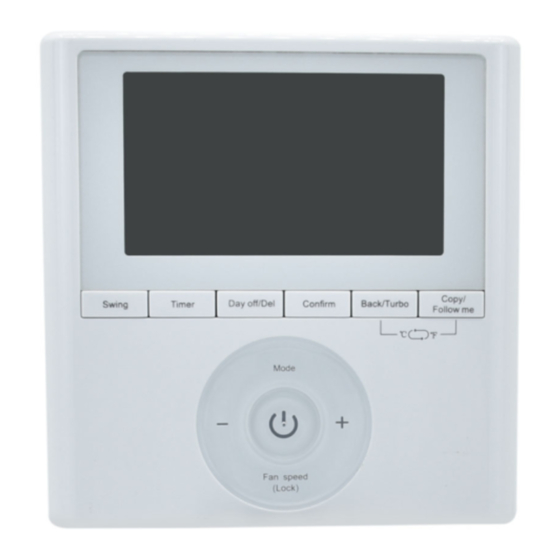
WIRED CONTROLLER DISPLAY Fig. 1 - Wired Controller Display 1. Operation mode indicator 2. Fan speed indicator 3. Left−right swing indicator 4. Up−down swing indicator 5. Not Available 6. Not Available 7. FOLLOW ME function indicator 8. Turbo/Auxiliary Heat function indicator F indicator 10. - Page 7 WIRED CONTROLLER DISPLAY Copy/ Swing Timer FOLLOW ME Mode Fan speed (Lock) Fig. 2 - Wired Controller Buttons 1. Mode 2. Power 3. Adjust 4. Fan Speed 5. Swing 6. Timer 7. Day Off/Del 8. Copy/FOLLOW ME 9. Back/Turbo 10. Confirm...
-
Page 8: Preparatory Operation
PREPARATORY OPERATION SET THE CURRENT DAY AND TIME Press TIMER for 3 seconds or more. The timer displays flashes. Timer Fig. 3 - Timer Press + or − to set the date. The selected date flashes. Fig. 4 - Day Date setting is complete and the time setting is ready after pressing TIMER or if nothing is pressed in 10 seconds. -
Page 9: Operation
Press + or − to set the current time. Press repeatedly to adjust the current time in 1 minute increments. Press and hold to adjust the current time. ex.Monday AM 11:20 Fig. 6 - Time The setting is complete after pressing TIMER or if no button is pressed for 10 seconds. Timer Fig. - Page 10 To set the operation mode Operation mode setting Press MODE to set the operation mode. Mode Fig. 9 - Operation Mode Press + or − to set the room temperature. Indoor Setting Temperature Range: 62~86 F(17~30 C)/62~88 F (17~31 C (depending on models)). Lower Raise Fig.
- Page 11 Fan speed (Lock) Fig. 11 - Fan Speed Press FOLLOW ME to select whether the room temperature is detected at the indoor unit or at the wired controller. Copy/FOLLOW ME Indoor Unit Fig. 12 - FOLLOW ME NOTE: When the FOLLOW ME function indication appears, the room temperature is detected at the wired remote controller.
- Page 12 Press LOCK for 3 seconds to activate the CHILD LOCK feature and lock all buttons on the wired controller. Press again for 3 seconds to deactivate. Fan speed (Lock) Fig. 13 - LOCK NOTE: When the child lock function is activated, the lock image appears. Press SWING and TIMER simultaneously for 3 seconds to disable the keypad tone.
- Page 13 Press BACK and COPY simultaneously for 3 seconds to alternate the temperature display between the F and C scale. Copy/ Back/Turbo FOLLOW ME Fig. 15 - F & C Temperature Selection Press TURBO to activate/deactivate the Turbo/Auxiliary Heat function. The turbo function sets the unit to reach the user’s present temperature in the shortest amount of time possible.
- Page 14 Press SWING to start the UP−DOWN SWING function. Press SWING again to stop. Swing Fig. 17 - Swing NOTE: Press SWING for 5 seconds to activate the LEFT−RIGHT SWING function. This function is not available on the indoor units. Use SWING to adjust the up and down airflow direction. Swing Fig.
-
Page 15: Timer Functions
TIMER FUNCTIONS Weekly Timer − Use to set the operating times for each day of the week. On Timer − Use to start the air conditioner operation. The timer operates and the air conditioner operation starts after the time has passed. Off Timer −... - Page 16 4. Press CONFIRM again to complete the settings. Confirm Fig. 22 - Confirm To set the Daily ON, OFF and ON/OFF TIMER 1. Press TIMER to select the DAY ON or DAY OFF. Timer Fig. 23 - Timer 2. Press CONFIRM and the clock display flashes. Confirm Fig.
- Page 17 4. Press + or − to set the OFF TIMER. Fig. 26 - + or − 5. Press CONFIRM to finish the setting. Confirm Fig. 27 - Confirm...
-
Page 18: Weekly Timer
WEEKLY TIMER 1. Press TIMER to select the week and press CONFIRM. Confirm Timer Fig. 28 - Weekly timer setting 2. Press + or − to select the day of the week and then press CONFIRM. Confirm Fig. 29 - Day of the week setting 3. - Page 19 4. Press + and − to set the time then press CONFIRM. Confirm Fig. 32 - Time Setting 5. Press + and − to set the operation mode then press CONFIRM. Confirm Fig. 33 - Operation Mode Setting 6. Press + and − to set the room temperature then press CONFIRM. Confirm Fig.
- Page 20 NOTE: The weekly timer setting can be returned to the previous step by pressing BACK. The current setting is restored. The controller will not save the weekly timer settings if there is no operation within 30 seconds. Weekly Timer Operation 1.
- Page 21 2. Press + or − to select the day of the week. Fig. 39 - + or − 3. Press DAY OFF to create an off day. Day off/Del mark is hidden ex.The DAY OFF is set for Wednesday Fig. 40 - DAY OFF 4.
- Page 22 1. In the weekly timer, press CONFIRM. Confirm Fig. 42 - Confirm 2. Press + or − to select the day to copy from. Fig. 43 - + or − 3. Press COPY, the letters CY appear on the LCD. Copy/FOLLOW ME Fig.
- Page 23 5. Press COPY to confirm. Copy/ FOLLOW ME ex. Copy the setting of Monday to Wednesday Fig. 46 - Copy 6. Other days can be copied by repeating steps 4 and 5. 7. Press CONFIRM to confirm the settings. Confirm Fig.
- Page 24 Delete the scheduled events in one day 1. During the weekly timer setting, press CONFIRM. Confirm Fig. 49 - Confirm 2. Press + and − to select the day of the week and then press CONFIRM. Confirm Fig. 50 - + and − 3.
-
Page 25: Fault Alarm Handling
FAULT ALARM HANDLING If the system does not properly operate except in the aforementioned cases or the aforementioned malfunctions are evident, investigate the system according to the following procedures. Table 1—Fault Alarm DISPLAY MALFUNCTION AND PROTECTION DEFINITION DIGITAL TUBE Communication error between wired controller and indoor unit The faceplate is abnormal Please check the indoor unit’s error display and review the owner’s manual if other error codes appear. - Page 26 Copyright 2018 CAC / BDP S 7310 W. Morris St. S Indianapolis, IN 46231 Edition Date: 01/18 Catalog No: OM-KSACN04(5)01-03 Manufacturer reserves the right to change, at any time, specifications and designs without notice and without obligations Replaces: OM-KSACN04(5)01-02...
Need help?
Do you have a question about the KSACN0401AAA and is the answer not in the manual?
Questions and answers