
Related Manuals for Midea KJRH-120H / BMKO-E


Summary of Contents for Midea KJRH-120H / BMKO-E
- Page 1 OPERATION MANUAL Thank you very much for purchasing our product. Before using your unit, please read this manual carefully and keep it for future reference.
- Page 3 ● This manual gives detailed description of the precautions that should be brought to your attention during operation. ● In order to ensure correct service of the wire controller please read this manual carefully before using the unit. ● For convenience of future reference, keep this manual after reading it.
- Page 4 PAGE CONTENTS 1 GENERAL SAFETY PRECAUTIONS..........1 2 A GLANCE OF THE USER INTERFACE........4 3 USING HOME PAGES..............6 4 HOW TO GO TO MENU STRUCTURE.........11 5 BASIC USAGE................12 6 INSTALLATION MANUAL............24...
- Page 5 1 GENERAL SAFETY PRECAUTIONS 1.1 About the documentation The original documentation is written in English. All other languages are translations. The precautions described in this document cover very important topics, follow them carefully. All activities described in the installation manual must be performed by an authorized installer.
- Page 6 WARNING Indicates a situation that could result in death or serious injury. CAUTION Indicates a situation that could result in minor or moderate injury. NOTICE Indicates a situation that could result in equipment or property damage. INFORMATION Indicates useful tips or additional information. 1.2 For the user If you are not sure how to operate the unit, contact your installer.
- Page 7 CAUTION Do NOT rinse the unit. This may cause electric shocks or fire. NOTICE ▪ Do NOT place any objects or equipment on top of the unit. ▪ Do NOT sit, climb or stand on the unit. Units are marked with the following symbol: This means that electrical and electronic products may not be mixed with unsorted household waste.
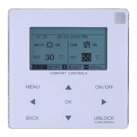
- Page 8 2 A GLANCE OF THE USER INTERFACE 2.1 The appearance of the wire control device Turn on or off the space operation Enter the menu mode or DHW structure from mode turn on or the home page off the function in the menu structure Navigate the...
- Page 9 2.2 Status icons The disinfect function is activated Prevent freezing icon The AHS Holiday away/home is activated (additional heating source such as gas boiler) is activated Silent mode is activated Timer icon Backup heater is activated A malfunction occured The compressor is activated Lock icon Shutoff Heat mode...
- Page 10 3 USING HOME PAGES 3.1 About home pages You can use the home pages to read out and change settings that are meant for daily usage. What you can see and do on the home pages is described where applicable. Depending on the system layout, the following home pages may be possible: ■...
- Page 11 21: 55 08 - 08 - 2015 SAT. MAIN TANK ② home page2: If you have set the WATER FLOW TEMP. is NON and ROOM TEMP. is YES. There will be only main page. The system has the function including floor heating and making hot water. The page will appear: NOTE: The interface should be installed in the floor heating room to check the room temperature.
- Page 12 ③ home page3: If you have set the WATER FLOW TEMP. is YES and ROOM TEMP. is YES. There will be main page and add. page. The system has the function including floor heating and air condition. The page will appear: MAIN 21: 55 08 - 08 - 2015 SAT.
- Page 13 ④ home page4: If you have set the WATER FLOW TEMP. is YES and ROOM TEMP. is YES. There will be main page and add. page. The system has the function including floor heating, air condition and making hot water. The page will appear: MAIN PAGE...
- Page 14 ⑤home page5: If you have set the WATER FLOW TEMP. is YES and ROOM TEMP. is YES. There will be main page and add. page. The system has the function, air condition. The page will appear: MAIN 21: 55 08 - 08 - 2015 SAT. PAGE MAIN 21: 55 08 - 08 - 2015 SAT.
- Page 15 4 HOW TO GO TO MENU STRUCTURE 4.1 About the menu structure You can use the menu structure to read out and configure settings that are NOT meant for daily usage. What you can see and do in the menu structure is described where applicable.
- Page 16 5 BASIC USAGE 5.1 Screen Unlock If the icon is on the screen, the controller is locked. The page is displayed: 21: 55 08 - 08 - 2015 SAT. MAIN TANK Press any key, the icon will flash.Long press the ''UNLOCK'' key.The icon will disappear,the interface can be controlled.
- Page 17 The interface will be locked if there is no handing for a long time(about 60 seconds:it can be set by the interface,see 6.7 SERVICE INFORMATION.) If the inerface is unlocked, long press "unlock",the interface will be locked. 21: 55 08 - 08 - 2015 SAT. MAIN TANK long press...
- Page 18 ■ The ON/OFF of the unit can be controlled by the interface if the ROOM TEHERMOSTAT is NON.(see ROOM THERMOSTAT SETTING on INSTALLATION &OWNER'S MANUAL) ■ Press ''◄''、''▲'' on home page,the black cursor will appear: 21: 55 08 - 08 - 2015 SAT. MAIN TANK 1)When the cursor is on space operation mode side (Including heat mode...
- Page 19 21: 55 08 - 08 - 2015 SAT. 21: 55 08 - 08 - 2015 SAT. MAIN MAIN ON/OFF 21: 55 08 - 08 - 2015 SAT. 21: 55 08 - 08 - 2015 SAT. ROOM ROOM ON/OFF...
- Page 20 Use the room thermostat to turn on or off the unit for space heating or cooling. ① The room thermostat is SET YES(see ROOM THERMOSAT on installation&ower‘s menual) the unit is turned on or off by the room thermostat,press on/off on the interface the page will display: 22:20 22-08-2018 SAT...
- Page 21 Use the interface to turn on or off the unit for DHW.Press ''►''、''▼''on home page,the black cursor will appear: 21: 55 08 - 08 - 2015 SAT. MAIN TANK 2)When the cursor is on DHW operation mode. Press ''ON/OFF'' key to turn on/off the DHW mode.
- Page 22 5.3 Adjusting the temerature Press ''◄''、''▲'' on home page, the black cursor will appear: 21: 55 08 - 08 - 2015 SAT. MAIN 55 C TANK ON/OFF ADJUST SCROLL ON/OFF ■ If the cursor is on the temperature, use the ''◄''、''►'' to select and use ''▼''、''▲'' to adjust the temperature.
- Page 23 21: 55 08 - 08 - 2015 SAT. MAIN TANK ON/OFF ADJUST SCROLL ON/OFF 21: 55 08 - 08 - 2015 SAT. ROOM...
- Page 24 21: 55 08 - 08 - 2015 SAT. MAIN TANK ON/OFF ADJUST SCROLL ON/OFF 21: 55 08 - 08 - 2015 SAT. MAIN TANK ON/OFF ADJUST SCROLL ON/OFF...
- Page 25 5.4 Adjusting space operation mode ■ Adjusting space operation mode by interface Go to ''MENU'' > ''SPACE OPERATION MODE'' . Press"OK", the page will appear: OPERATION MODE Operation mode setting: HEAT AUTO COOL CONFIRM SCROLL ■ There are three modes to be selected including heat, cool and auto. mode. Use the ''◄'',''►'' to scroll, press ”OK”...
- Page 26 OPERATION MODE Operation mode setting: HEAT CONFIRM SCROLL ■ The operation mode can not be changed see cool MODE SETTING on installation ower's menual. If you Then the space operation mode is… select… Always heat mode heat Always cool mode cool Automatically changed by the software based on the outdoor temperature (and depending on installer settings also the indoor...
- Page 27 ■ Adjust space operation mode by the room thermostat see room thermostat on installation&ower's menual. Go to MENU>OPERATION MODE, if you press any key to select or adjust, the page will appear: 22:20 22-08-2018 WED. Cool/heat mode is controlled by the room thermostat.
- Page 28 6 INSTALLATION MANUAL 6.1 Safety precaution Read the safety precautions carefully before installing the unit. Stated below are important safety issues that must be obeyed. Conform there is no abnormal phenomena during test operation after complete, then hand the manual to the user. Meaning of marks: Means improper handling may lead to personal death or WARNING...
- Page 29 CAUTION Do not install the unit in a place vulnerable to leakage of flammable gases. Once flammable gases are leaked and left around the wire controller, fire may occure. The wiring should adapt to the wire controller current. Otherwise, electric leakage or heating may occur and result in fire. The specified cables shall be applied in the wiring.
- Page 30 Name Remarks Qty. Wire controller Cross round head wood GB950-86 M4X20 (For Mounting on the Wall) mounting screw M4X25 GB823-88 Cross round head (For Mounting on the mounting screw Electrical Switch Box) Installation & Owner's Manual This accessory is used when Plastic bolt install the centralized control inside the electric cabinet...
- Page 31 6.2.3 Note to installation of wire controller: 1) This installation manual contains information about the procedure of installing Wired Remote Controller. Please refer to Indoor Unit Installation Manual for connecting between Wired Remote Controller and Indoor Unit. 2) Circuit of Wired Remote Controller is low voltage circuit. Never connect it with a standard 220V/380V circuit or put it into a same Wiring Tube with the circuit.
- Page 32 6.3.1 Structure size figure 20mm 120mm Figure A 46mm 60mm...
- Page 33 6.3.2 Wiring Main Unit control box Wire controller Input Voltage(A/B) 13.5VAC Wiring size 0.75mm...
- Page 34 6.3.3 Back cover installation Buckling position Back cover Front cover Straight head screwdriver Screw hole installed on the wall,use three GB950-86 M4X20...
- Page 35 Screw hole fixed on the wall,use one GB950-86 M4X20 Screw hole installed on 86 Electrician box, use two M4X25 GB823-88 Back cover Signal switching wires...
- Page 36 1) Use straight head screwdriver to insert into 6.3.4 Wire outlet the buckling position in the bottom of wire controller, and spin the screwdriver to take down the back cover. (Pay attention to spinning direction, otherwise will damage the back cover!) 2) Use three GB950-86 M4X20 screws to directly install the back cover on the wall.
- Page 37 Wall hole and wiring hole 60mm Wiring Diameter:Φ8--Φ10 hole Putty Trap Putty Avoid the water enter into the Putty wired remote controller, use trap and putty to seal the Trap connectors of wires during Trap wiring installation.
- Page 38 6.4 Front cover installation After adjusting the front cover and then buckle the front cover; avoid clamping the communication switching wire during installation. Sensor can not be affected with damp.
- Page 39 Correct install the back cover and firmly buckle the front cover and back cover, otherwise will make the front cover drop off.
- Page 40 MD16IU-013AW 16110600000065...
Need help?
Do you have a question about the KJRH-120H / BMKO-E and is the answer not in the manual?
Questions and answers