
Related Manuals for KEB COMBIVERT S4


Summary of Contents for KEB COMBIVERT S4
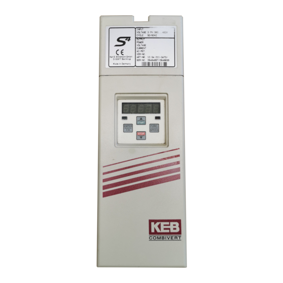
- Page 1 BETRIEBSANLEITUNG INSTRUCTION MANUAL KEB COMBIVERT S4 Größe D / E Size D / E ANTRIEBSTECHNIK 07/96...
- Page 2 This instruction manual – is applicable for the servo system KEB COMBIVERT S4 – must be made available to every user Before working with this unit the user must familiarize himself with it. This is especially true concerning knowledge and observance of the safety and warning guides.
-
Page 3: Table Of Contents
Table of Contents ANTRIEBSTECHNIK Introduction KEB COMBIDYN S4 ........E 4 Part Code ............E 4 Parameter Description ......E 28 Application ............. E 4 Drive Mode Operating Specifications Setting Possibilities ........E 37 Moving or Rotating Parts ....... E 5 Condition ............. -
Page 4: Introduction
The digital servo controller KEB COMBIVERT S4 serves exclusively for the control and regulation of the supplied synchronous servo motor KEB COMBIVERT SM. The servo system KEB COMBIVERT S4 is a highly dynamic control drive it is connected and ready for operation within a short time. -
Page 5: Operating Specifications
When deviated from, malfunctions and damages may occur in isolated cases. – The servo controller KEB COMBIVERT S4 is only designed for a fixed connection. – Do not interchange power cable and motor line. – Lay control and power lines separately (min. 10 cm distance). -
Page 6: Interference Protection Of Servo Controller
– Frequent switching between mains and servo controller is not permitted! – The switching between motor and servo controller during operation is prohibited! – The servo system KEB COMBIVERT S4 is to be operated under suitable conditions (see Ambient Condition). -
Page 7: Control Cabinet Installation
– Avoid penetration of dust into the servo controller. For installation in a dust- proof housing sufficient heat dissipation must be provided. – Do not operate the servo system KEB COMBIVERT S4 in explosion-protected rooms. – Ensure sufficient heat emmission of the servo motor. -
Page 8: Calculations
CURRENT CURRENT AC-MOT. 4,0 KW, 2/4 P, 50/60 HZ AC-MOT. 4,0 KW, 2/4 P, 50/60 HZ AC-MOT. 4,0 KW, 2/4 P, 50/60 HZ XXXXXXXXXXXXXXX˜ XXXXXXXXXXXXXXX˜ XXXXXXXXXXXXXXX˜ KEB Antriebstechnik VER-NO. KEB Antriebstechnik VER-NO. KEB Antriebstechnik VER-NO. Karl E. Brinkmann GmbH ART-NO. -
Page 9: Technical Data
4. Technical Data ANTRIEBSTECHNIK... -
Page 10: Technical Data 400 V Class
4.2 Technical Data 400 V Class Motor size Rated speed [min 4000 6000 3000 4000 3000 4000 6000 3000 4000 3000 3000 2000 3000 2000 Nominal power [kW] 0,92 Basic torque M [Nm] 11,0 Stall torque M [Nm] 12,0 Pulse torque [Nm] max. - Page 11 Motor size Rated speed [min 6000 6000 4000 6000 4000 4000 3000 4000 2000 3000 4000 2000 3000 Nominal power [kW] Basic torque M [Nm] 10,0 13,0 11,2 17,0 13,0 Stall torque M [Nm] 12,0 15,5 20,5 Pulse torque [Nm] max.
-
Page 12: Torque-Speed Characteristics
4.3 Torque-Speed Characteristics Rated speed 6000 U/min = 1,6 Size short-time duty = 0,34 = 0,32 continuous duty 5000 6000 8000 = 2,4 Size short-time duty = 0,5 = 0,48 continuous duty 6000 6500 8000 = 3,0 Size short-time duty = 0,65 = 0,6 continuous duty... - Page 13 3000 U/min 4000 U/min 6000 U/min Rated speed = 4,0 = 3,75 = 3,0 Size short-time duty short-time duty short-time duty = 0,95 = 0,95 = 0,95 = 0,75 = 0,6 = 0,8 continuous duty continuous duty continuous duty 2000 3000 4000 2500...
- Page 14 Rated speed 3000 U/min 4000 U/min 6000 U/min = 16,0 = 15,0 = 10,5 Size short-time duty short-time duty short-time duty = 3,4 = 3,4 = 3,4 = 3,2 = 2,1 = 3,0 continuous duty continuous duty continuous duty 2500 3000 4000 3750 5750...
- Page 15 Rated speed 2000 U/min 3000 U/min 4000 U/min = 35,0 = 32,5 = 26,0 Size short-time duty short-time duty = 8,4 short-time duty = 8,4 = 8,4 = 5,2 = 6,5 = 7,0 continuous duty continuous duty continuous duty 1000 2500 3000 2500 3500 4000...
-
Page 16: Technical Data 230 V / 400 V Class
4. Technical Data 4.4 Technical Data 230 V / 400 V Class For horizontal positioning: If the radial force takes no effect For vertical positioning: [N] = F – (10 • d at x = l /2, it applies – F kx + 0,5 •... -
Page 17: Dimensions
XXXXXXXXXXXX CURRENT XXXXXXXXXXXX AC-MOT. 4,0 KW, 2/4 P, 50/60 HZ AC-MOT. 4,0 KW, 2/4 P, 50/60 HZ VER-NO. XXXXXXXXXXXXXXX˜ VER-NO. XXXXXXXXXXXXXXX˜ KEB Antriebstechnik KEB Antriebstechnik Karl E. Brinkmann GmbH ART-NO. XX.F4.XXX-XXXX Karl E. Brinkmann GmbH ART-NO. XX.F4.XXX-XXXX D-32677 Barntrup SER-NO. -
Page 18: Connection
6. Connection 6.1 Survey E 18... - Page 19 6. Connection ANTRIEBSTECHNIK 9 pole Sub-D-socket ! Operator only Parameterizing Interface optional ! see Page E 42 "Accessoires" Terminal strip X1 Connection of the control terminals AMP tab connector Shield connection / earthing 9 pole Sub-D-socket X3 Incermental encoder simulation 15 pole Sub-D-socket X4 resolver input / SIN/COS encoder input Terminal strip X2...
-
Page 20: 1-Phase Connection 230 V Class
6. Connection 6.2 1-phase Connection Remove or plug in the power connector only at switched off 230 V Class unit and disconnected power supply ! Observe the correct phase sequence for the connection of the servo motor ! Protective earth conductor U, V, W Motor L1, L2... -
Page 21: 3-Phase Connection 230 / 400 V Class
6. Connection ANTRIEBSTECHNIK 6.3 3-phase Connection Absolutely ensure the observance of the supply voltage 230 V / 400 V Class of the servo controller (3 x 230 V / 3 x 400 V) ! Remove or plug in the power connector only at switched off unit and disconnected power supply ! Observe the correct phase sequence for the connection of the servo motor ! -
Page 22: Connection Incremental Encoder Simulation
6. Connection The 9-pole Sub-D connector for incremental encoder simulation serves for the 6.4 Connection Incremental connection of a paramount control (e.g. positioning control). Encoder Simulation Remove or plug in the connector only at switched off unit and disconnected power supply ! Servo controller PIN Nr. -
Page 23: Connection Sin/Cos Encoder
GND Sensor GND Sensor brown/green Cables For the servo system KEB COMBIVERT S4 factory-assembled motor, resolver and encoder cables are available in the lengths 5m, 10m, 15m und 20m. 00.S4.009–0005 Cable length 05 = 5 m 10 = 10 m... -
Page 24: Control Terminal Strip X2
6. Connection 6.8 Control Terminal Strip X2 Terminal Designa- Function tion Control release Reset Ω Release of rotation direction (limit switch ) forward Digital inputs: +12…33 V / Ri = 2 k Release of rotation direction (limit switch ) reverse PNP Input for jogging speed forward Potential-separated Input for jogging speed reverse... -
Page 25: Digital Inputs / Outputs
6. Connection ANTRIEBSTECHNIK +24 V intern 6.8.1 Digital Inputs / Outputs PNP-Logic shield- connection shield- 6.8.2 Analoge Inputs / Outputs connection CRF COM REF1 REF1 REF2 REF2 A1 – – Without analog torque limitation -10V…+10V Set value source e.g.: PLC shield- connection CRF COM REF1 REF1 REF2 REF2 A1... -
Page 26: Operation
7. Operation CP-Parameter 7.1 Parameter Structure (CP.0 … CP.24) Read-Only Parameters Programmable Parameters can only be read they can be changed (CP.0, cannot be changed. CP.7 … CP.13, CP.15 … CP.24) (CP.1 …CP.6, CP.14) NO-ENTER-Parameters ENTER-Parameters are programmable parameters, a are programmable parameters a change is accepted and stored change must be confirmed with... -
Page 27: Selection And Changing Of Parameters
7. Operation ANTRIEBSTECHNIK 7.3 Selection and Changing When switching on the servo controller the of Parameters display always shows the value of parameter CP.1 (Status Display). Raising / decreasing Raising / decreasing of parameter number of parameter value START START Display of Display of parameter number... -
Page 28: Parameter Description
8. Parameter Description The servo controller is supplied ex factory without password protection, i.e. all programmable parameters can be changed. After the parameterizing the unit can be locked against unauthorized access. The adjusted mode is stored. The passwords are listed in page E 48! Password Input Parameter enabled... - Page 29 8. Parameter Description ANTRIEBSTECHNIK The status display indicates the current operating condition of the servo controller. Possible indications and their meaning are listed in the following: no Operation – Control release (terminal X2.1)not activated Status Display – Modulation switched off –...
- Page 30 8. Parameter Description Indication of the current torque in newtonmeter. Resolution: 0,1 Nm Current Torque Indication of preset setpoint speed in U/min. Resolution: 0,5 U/min Positive speed: Rotation "forward" or no sense of rotation Negative Speed: Rotation "reverse" Setpoint Speed Display The parameter defines the time required to accelerate form 0 U/min to rated speed of the servo system (3000/4000/6000 U/min).
- Page 31 8. Parameter Description ANTRIEBSTECHNIK The parameter defines the time required to decelerate from rated speed of the servo system (3000/4000/6000 U/min) to 0 U/min. The behaviour of the actual deceleration time is proportional to the speed change. Rated speed [U/min] Deceleration Time 3000/ Setting range:...
- Page 32 8. Parameter Description Presetting of speed that can be activated via digital inputs I1 or I2. Depending on the assignment of the inputs the jogging speed can be activated by direction of rotation "forward" or alternatively direction of rotation "reverse" . If both directions of roation are preset at the same time then rotation "forward"...
- Page 33 8. Parameter Description ANTRIEBSTECHNIK This parameter determines the Setting range: 0…6 response of the drive to an external Resolution: fault. Factory setting: Behaviour at External Fault Remarks: ENTER-Parameter Customer setting: Value Response of Drive → Error message: E.EF Immediate disconnection of inverter! ! To restart eliminate the fault and make a Reset ! →...
- Page 34 8. Parameter Description A zero point hysteresis of the analog reference input REF1 is adjusted with this parameter. Voltage fluctuations and ripple voltages around the zero point of the setpoint value do not cause any drifting of the motor. ! Only when CP.7 or CP.8 > 0,00 s ! Zero Point Hysteresis REF 1 Adjustment of parameter CP.7 and CP.8 must be...
- Page 35 8. Parameter Description ANTRIEBSTECHNIK The analog output A2 (terminal X2.19) outputs the current speed of the servo systems. Parameter CP.20 defines the amplification of the analog output signal. Amplification Output A2 Setting range: -20…+20 +10 V Resolution: 0,01 Factory setting: +/–...
- Page 36 8. Parameter Description Defines the switching condition of Setting range: 0…20 digital output D2. Resolution: Factory setting: ! Refer to table below ! Switching Condition Remarks: ENTER–Parameter Customer setting: Output D2 Switching Conditions Digital output D1 and D2 Value Switching condition always active always active system switched on;...
-
Page 37: Drive Mode
9. Drive Mode ANTRIEBSTECHNIK The Drive Mode is a special operating mode of the KEB COMBIVERT. It allows Drive Mode an easy manual startup. To activate the Drive Mode enter the corresponding password in CP.0. The passwords are listed on page E 48! 9.1 Setting Possibilities... -
Page 38: Rotation Presetting
9. Drive Mode Rotation Presetting Presetting Possibilities: F = forward (clockwise rotation) r = reverse (anti-clockwise rotation) Every actuation of the ENTER-key causes a change of the rotation. START START ENTER FUNC. ENTER ENTER FUNC. SPEED SPEED STOP STOP Start / Stop / RUN Status "Stop"... -
Page 39: Accessories
Resistor provided and a sufficient distance to the KEB COMBIVERT S4 must be kept. Do not mount the external braking resistor below the servo controller ! 14.56.080 –... -
Page 40: Radio Interference Suppression Filter
10. Accessories The servo controller KEB COMBIVERT S4 can be supplied ex factory with internal 10.2 Radio Interference radio interference suppression filter. Base filters are available for the unit sizes 03, Suppression Filter 05 and 10. Unit size 10 can only be delivered with an external filter. -
Page 41: Braking Motor
10. Accessories ANTRIEBSTECHNIK The synchronous servo motor is alternatively available with permanent-magnet 10.3 Braking Motor brake. Application: – permanent-magnet single-disc holding brake – fail-safe brake to switch around standstill – breakdown-emergency braking (permissible on request) 10.3.1 Technical Data Servo motor Size M1…M4 01…04... -
Page 42: Operator
Part.-No. 00.F4.010-1009 Part.-No. 00.F4.010-1009 In the Interface operator there is an additionally isolated RS232/RS485-Interface integrated. The RS232/485-parameterizing interface expands the KEB COMBIVERT S4 for communication with data communications equipment. Suitable wiring permits the physically isolated data transmission. RS232/RS485 PE-Connection ! Connection see page E 23 ! PIN No. -
Page 43: Adjustment Assistance Speed Controller
11. Adjustment Assistance Speed Controller ANTRIEBSTECHNIK Problem: very long transient Problem: Speed overshoot too high Assistance:Increase P-component (CP.12); Assistance:Increase P-component (CP.12); eventually reduce I-component (CP.13) eventually reduce I-component (CP.13) Problem: Maintained vibration Problem: Transient slow/ remaining control deviation Assistance:Increase P-component (CP.12) Assistance:Increase I-component (CP.13) Problem: Overshoot too long Problem: Maintained vibration with high amplitude... -
Page 44: Error Diagnosis
12. Error Diagnosis Display Fault Description Occurs when the intermediate circuit voltage drops Underpotential below the permissible value. Occurs when the intermediate circuit voltage rises Overpotential above the permissible value. Occurs when the output voltage exceeds the permissible Overcurrent value. Occurs when the servo controller is overloaded. - Page 45 12. Error Diagnosis ANTRIEBSTECHNIK Possible Cause Fault Remedy - Input voltage too low or unstable - Check voltage suppply - Voltage losses due to incorrect cabling - Check input line - Check voltage suppply - Input voltage too high - Connect braking resistor - Retarding torque too high - Short-circuit or ground fault at the output - Determine exact cause and remove, next re-start...
- Page 46 E 46...
- Page 47 ANTRIEBSTECHNIK E 47...
- Page 48 Passwords ----------------------------------------------------------------------------------- ----------------------------------------------------------------------------------- Passwords Customer "read only" Password Customer "on" Password Drive Password E 48...
- Page 49 ANTRIEBSTECHNIK...
- Page 50 Karl E. Brinkmann GmbH Postfach 11 09 • Försterweg 36 - 38 D - 32677 Barntrup • Telefon 0 52 63 / 4 01-0 ANTRIEBSTECHNIK Teletex 5 263 811 keb • Telefax 4 01 - 116...
Need help?
Do you have a question about the COMBIVERT S4 and is the answer not in the manual?
Questions and answers