
Related Manuals for tams elektronik Multi-Decoder MD-2


Summary of Contents for tams elektronik Multi-Decoder MD-2
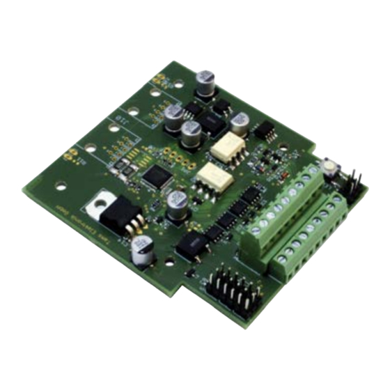
- Page 1 Manual Multi-Decoder MD-2 Item no. 43-03126 | 43-03127 8- fold servo decoder and 4-fold turnout decoder tams elektronik n n n...
- Page 2 English Multi-Decoder MD-2 © 12/2019 Tams Elektronik GmbH All rights reserved. No part of this publication may be reproduced or transmitted in any form or by any means, electronic or mechanical, including photocopying, without prior permission in writing from Tams Elektronik GmbH.
-
Page 3: Table Of Contents
Multi-Decoder MD-2 English Table of Contents 1. Getting started................4 2. Safety instructions...............5 3. Operation overview..............7 4. Technical specifications..............12 5. Connecting the decoder.............14 5.1. Connecting servos............14 5.2. Connecting push-buttons (→ Operating mode 2)....16 5.3. Connecting accessories (→ Operating mode 1)....17 5.4. Power supply..............19 5.5. -
Page 4: Getting Started
Intended use The Multi-Decoder MD-2 is designed to be operated according to the instructions in this manual in digital model railway layouts. Any other use is inappropriate and invalidates any guarantees. -
Page 5: Safety Instructions
Multi-Decoder MD-2 English Required materials In order to connect the decoder, you need wire. Recommended diameters: > 0,05 mm² for the connections to LEDs, push buttons and switches; > 0,25 mm² for all other connections. When using motor-run turnouts, you need an additional adapter AMW-2 for each turnout (item-no. - Page 6 English Multi-Decoder MD-2 can cause serious injury due to electrical shock. Take the following precautions to prevent this danger: Never perform wiring on a powered module. Assembling and mounting the kit should only be done in closed, clean, dry rooms. Beware of humidity.
-
Page 7: Operation Overview
Multi-Decoder MD-2 English 3. Operation overview The MD-2.BiDiB is a stationary decoder used to control a maximum of 8 servos. In addition, coil driven turnouts or semaphore signals, decouplers or other accessories or push-buttons for manual activation of the servos can be connected. - Page 8 English Multi-Decoder MD-2 Operating mode 2: 8-fold servo decoder with push-buttons for manual activation Connecting area 1 8 servos ("pin headers") (8-fold servo decoder) Connecting area 2 8 push-buttons for toggling between the ("terminal strips") servos´ two end positions (as well...
- Page 9 Multi-Decoder MD-2 English Motion sequences You can set separately for each of the 8 servos: Starting and end position Rotational speed Simple linear motion curve or linear motion curve with teetering when reaching the end position (to be adjusted separately for the...
- Page 10 Motorola format only. Feedback via RailCom (according to RCN-217) The Multi-Decoder MD-2 is RailCom compatible, i.e. the decoder is able to pass the RailCom messages via the rails to special RailCom detectors.
- Page 11 Power supply The Multi-Decoder MD-2 can either be supplied by the central unit or a booster. In order to release the digital electric circuit it is also possible to supply the decoder by a transformer of its own instead.
-
Page 12: Technical Specifications
English Multi-Decoder MD-2 4. Technical specifications Data format DCC, Motorola Adress range MM: 1020 turnout addresses DCC: 2040 turnout addresses Hint: The adress range to be used also depends from the central unit. Feedback log RailCom Supply voltage Digital voltage of the central unit or 14 –... - Page 13 Multi-Decoder MD-2 English Ambient temperature in use 0 ... +60 °C Ambient temperature in storage -10 ... +80 °C Comparative humidity allowed max. 85 % Dimensions of the PCB approx. 72 x 82 mm Dimensions including housing approx. 100 x 90 x 35 mm Weight of the assembled board / approx.
-
Page 14: Connecting The Decoder
English Multi-Decoder MD-2 5. Connecting the decoder Make the connections one after the other to: servos (connecting area 1) push-buttons (connecting area 2, operating mode 2) or turnouts, other solenoid accessories and/or other accessories (connecting area 2, operating mode 1) ... - Page 15 Multi-Decoder MD-2 English servo 1 GND (-) VCC (+) signal servo 2 GND (-) VCC (+) signal … servo 8 GND (-) VCC (+) signal Caution: The maximum current for connecting area 1 as well as the maximum current per servo connection is 1,000 mA (see section 4.
-
Page 16: Connecting Push-Buttons (→ Operating Mode 2)
English Multi-Decoder MD-2 5.2. Connecting push-buttons (→ Operating mode 2) The connecting area 2 is equipped with terminal strips to plug in and screw on the connecting wires for the push-buttons. 1 | 2 Push-button for servo 5 3 | 2... -
Page 17: Connecting Accessories (→ Operating Mode 1)
Multi-Decoder MD-2 English 5.3. Connecting accessories (→ Operating mode 1) The connecting area 2 is equipped with terminal strips to plug in and screw on the connecting wires for turnouts and other (solenoid) accessories. You can connect to each of the four output pairs either one solenoid accessory or two other accessories. - Page 18 English Multi-Decoder MD-2 Output Solenoid accessory / turnout 2 Turnout 2 pair 2 or switching contact 3 "diverging" (2r) (T2) Return conductor for T(urnout)2 Solenoid accessory / turnout 2 Turnout 2 or switching contact 4 "straight" (2g) Output Solenoid accessory / turnout 4...
-
Page 19: Power Supply
Multi-Decoder MD-2 English 5.4. Power supply You can supply the decoder either via the central unit or via a seperate transformer according to the two following diagrams. Power supply / transformer (~) Input DCC signal not in use Power supply / transformer (~) - Page 20 English Multi-Decoder MD-2 Power supply via separate transformer Caution: When connecting several devices to the same voltage supply, generally all connections have to be polarised identically. Otherwise a short circuit will occur, possibly damaging connected devices. Page 20...
-
Page 21: Connection Examples
Multi-Decoder MD-2 English 5.5. Connection examples Connecting coil driven turnouts Connection of turnouts to terminals 4 to 6 ("turnout 4") Connecting decouplers Connection of turnouts to terminals 4 to 6 ("turnout 4") Page 21... -
Page 22: Programming The Decoder
Changing the other decoder´s features is impossible with Motorola central units. 6.1. Programming decoder addresses Addresses of the Multi-Decoder MD-2 Depending on the set operating mode, two or three consecutive quadruple accessory decoder address blocks are assigned to each decoder address. - Page 23 Multi-Decoder MD-2 English Setting the address with the push-button The easiest way to program the addresses is using the programming push-button. With Motorola central units the address can be set via the programming push-button only. In order to set the address via the programming push-button perform the following steps: 1.
- Page 24 English Multi-Decoder MD-2 Setting addresses via CVs Instead of using the programming push-button, you can set the decoder´s address via CVs with your DCC central unit. The accessory decoder address used to send the switching commands result from: Decoder address x 4...
-
Page 25: Possible Settings And Default Values
Multi-Decoder MD-2 English 6.2. Possible settings and default values Meaning Default value Operation Operation mode 1 Operation mode 1 mode ("servos + turnouts") (CV 39) Operation mode 2 (" servos + push-buttons") RailCom Channel 1 and/or 2 on / off... -
Page 26: Programming Cvs
English Multi-Decoder MD-2 Settings for connecting area 2 (operating mode 1) Meaning Default value On-Time 0 … 25,5 s for alle 4 pairs of outputs: 0,3 s (CV 31...38) (to be set individually for each pair of outputs) Hint: Setting the value "0" for the on-time allows the use as a changeover switch (switching decoder). - Page 27 Multi-Decoder MD-2 English Settings for RailCom Input value Remarks and tips (Default) RailCom 0, 1, 2, 3 (3) RailCom in channel 1 off | on 0 | 1 channel RailCom in channel 2 off | on 0 | 2 RailCom...
- Page 28 English Multi-Decoder MD-2 No. Input value Remarks and tips (Default) Settings for 40 0...255 (100) LS = left stop servo 1 each step = 100 µs (0,1 msec) 41 0...255 (150) RS = right stop each step = 100 µs (0,1 msec) 42 0...255 (10)
- Page 29 Multi-Decoder MD-2 English No. Input value Remarks and tips (Default) Settings for 46 0.255 (100) LS = left stop servo 3 47 0...255 (150) RS = right stop 48 0...255 (10) V = velocity 68* 0,16,32,48 (0) Teetering / direction...
- Page 30 English Multi-Decoder MD-2 No. Input value Remarks and tips (Default) Settings for 55 0.255 (100) LS = left stop servo 6 56 0...255 (150) RS = right stop 57 0...255 (10) V = velocity 69* 0,4,8,12 (0) Teetering / direction...
- Page 31 Multi-Decoder MD-2 English Input value Remarks and tips (Default) Servo follow- 0...255 (5) each step = 100 msec (0.1 sec) up time By setting a servo follow-up time you can avoid that the servo signal is switched off immediately after the regulating time calculated by the deocder has elapsed und thus the servo movement is interrupted before reaching the stop e.g.
-
Page 32: Check List For Troubleshooting
English Multi-Decoder MD-2 7. Check list for troubleshooting Parts are getting too hot and/or start to smoke. Disconnect the system from the mains immediately! Possible cause: One or more connections have been made incorrectly. à Check the connections. In case in- or outputs of the decoder have been connected to a live wire (e.g. - Page 33 Multi-Decoder MD-2 English After programming the address the decoder does not react to switching commands. Possible cause: When programming the decoder address via CV you set the decoder address. To switch the decoder accessory decoder addresses are used. Enter the accessory decoder address to switch (see also page 24).
- Page 34 English Multi-Decoder MD-2 Hotline If problems with your decoder occur, our hotline is pleased to help you (mail address on the last page). Repairs You can send in a defective decoder for repair (address on the last page). In case of guarantee the repair is free of charge for you. With damages not covered by guarantee, the maximum fee for the repair is 50 % of the current sales price according to our valid price list.
-
Page 35: Guarantee Bond
Multi-Decoder MD-2 English 8. Guarantee bond For this product we issue voluntarily a guarantee of 2 years from the date of purchase by the first customer, but in maximum 3 years after the end of series production. The first customer is the consumer first... -
Page 36: Eu Declaration Of Conformity
English Multi-Decoder MD-2 9. EU declaration of conformity This product conforms with the EC-directives mentioned below and is therefore CE certified. 2004/108/EG on electromagnetic. Underlying standards: EN 55014-1 and EN 61000-6-3. To guarantee the electromagnetic tolerance in operation you must take the following precautions: ... - Page 37 Multi-Decoder MD-2 English Page 37...
- Page 38 English Multi-Decoder MD-2 Page 38...
- Page 39 Multi-Decoder MD-2 English Page 39...
- Page 40 Information and tips: http://www.tams-online.de Warranty and service: Tams Elektronik GmbH Fuhrberger Straße 4 DE-30625 Hannover fon: +49 (0)511 / 55 60 60 fax: +49 (0)511 / 55 61 61 e-mail: modellbahn@tams-online.de...
Need help?
Do you have a question about the Multi-Decoder MD-2 and is the answer not in the manual?
Questions and answers