Table of Contents
Advertisement
Quick Links
Advertisement
Table of Contents

Related Manuals for tams elektronik LD-G-43


Summary of Contents for tams elektronik LD-G-43
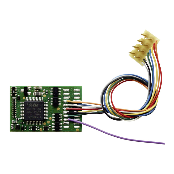
- Page 1 LD-G-43 Locomotive decoders Manual DCC DCC-A LD-G-43 without connecting cables Item no. 41-04430 LD-G-43 with connecting cables Item no. 41-04431 LD-G-43 with NEM 652 connector Item no. 41-04432 LD-G-43 with PluX22 plug Item no. 41-04433 tams elektronik n n n...
- Page 2 © Tams Elektronik GmbH All rights reserved, in particular the right of reproduction, distribution and translation. Copies, reproductions and alterations in any form require the written permission of Tams Elektronik GmbH. We reserve the right to make technical changes. Printing the manual The formatting is optimised for double-sided printing.
-
Page 3: Table Of Contents
3.4. Pin assignment LD-G-43 | Front side..............25 3.5. Pin assignment LD-G-43 | Rear side..............27 3.6. Using decoders with interface connectors.............28 3.7. Use of the LD-G-43 in locomotives with AC motor..........29 3.8. Mounting decoders without interface..............29 3.9. Connecting LEDs to the function outputs..............31 3.10. - Page 4 LD-G-43 tams elektronik 4. Programming......................36 4.1. Programming with DCC central units..............36 4.2. Programming with Motorola central units.............37 5. Configuration variables and registers................38 5.1. Basic settings.....................38 5.2. Setting the address.....................39 5.3. Setting the motor control..................40 5.4. Function mapping....................42 5.5. Effects of the outputs..................48 5.6.
-
Page 5: Getting Started
N.B. For technical reasons it is possible that the PCB is not completely inserted. This is not a fault. one electrolytic capacitor, capacity: 220 µF, proof voltage: 35 V Versions LD-G-43 Connecting wires / Interface (item number) 41-04430... - Page 6 LD-G-43 tams elektronik Connection to an AC motor a load control adapter LRA (item no. 70-02105 or 70-02106) or a permanent magnet (e.g. no. 70-04100, 70-04200 or 70-04300) or a motor modification set (e.g. no. 70-40110, 70-40210 or 70-40310)
-
Page 7: Intended Use
LD-G-43 1.3. Intended use The locomotive decoder LD-G-43 is designed to be operated according to the instructions in this manual in model building, especially in digital model railroad layouts. Any other use is inappropriate and invalidates any guarantees. -
Page 8: Operation Overview
LD-G-43 tams elektronik 2. Operation overview 2.1. Digital operation The locomotive decoder is a multiple protocol decoder, that can operate with and automatically recognise both DCC or Motorola formats. Motorola II (MM II) according to NMRA and RCN-standard Number of 127 basic addresses or 10.239... -
Page 9: Analogue Mode
LD-G-43 2.2. Analogue mode The locomotive decoder LD-G-43 can also be used in analogue model railway layouts run with an AC or DC speed control. The decoder automatically detects whether an AC or DC speed control is used to power the layout. -
Page 10: Overload Protection
2.3. Overload protection The locomotive decoder LD-G-43 has an overload protection which protects it from damage in case of exceeding the permissible total current or a short circuit at the motor output (the maximum form of an overload). -
Page 11: Motor Control
LD-G-43 2.4. Motor control Pulse width modulation The LD-G-43 is designed to optimally control DC motors. With a PWM of 25 kHz, it is also suitable for coreless motors. Load control The LD-G-43 has a load control. The load control influences the motor voltage to keep the locomotive with a set speed level at constant velocity, independent of additional loads (e.g. - Page 12 LD-G-43 tams elektronik a: Linear characteristic from a: Linear characteristic from a: Linear characteristic from start and maximum voltage start and maximum voltage start and maximum voltage b: Linear characteristic from c: Shunting gear = 50 % of d: alternative characteristic...
- Page 13 CV and on the speed level when the braking process is triggered. An exact stop at stopping points is not possible. For the LD-G-43 a constant braking distance can be defined, which the locomotive should cover when changing from any speed level to speed level 0. The braking distance corresponds to the distance that the locomotive covers with the set brake delay at the highest possible speed level until it comes to a stop.
-
Page 14: Automated Processes
/ a function key. 2.5.1. ABC braking procedure The LD-G-43 locomotive decoder, with the appropriate CV setting, detects when entering an ABC braking section that an asymmetrical track voltage is present and then automatically reduces the driving speed with the set brake delay or braking distance. It can be set to... -
Page 15: Braking At Dc Voltage
2.5.2. Braking at DC voltage The locomotive decoder LD-G-43 reacts to the application of a pure DC voltage (e.g. Märklin** braking section) with the corresponding CV setting and then automatically reduces the driving speed with the set brake delay or the set braking distance. -
Page 16: Automatic Uncoupling ("Uncoupling Waltz")
LD-G-43 tams elektronik 2.5.3. Automatic uncoupling ("uncoupling waltz") By programming the CV accordingly, the complete uncoupling process can be triggered with one function. After switching on the function, the locomotive first moves a little bit against the set direction of travel in order to relieve the coupling. Then the function output to which the coupling is connected is switched on for the set time. -
Page 17: Outputs And Interfaces
LD-G-43 2.6. Outputs and interfaces Function outputs The decoder has eight function outputs (F0f, F0r, AUX1 to AUX6) with a maximum current of 300 mA each for the connection of additional accessories (e.g. lighting, smoke generator, electrical coupling). Note: The maximum total current of the decoder (including motor) is 1,500 mA. - Page 18 LD-G-43 tams elektronik Effects of the function outputs Kicking: The output first receives full voltage for a maximum of CV programming approx. 25.5 seconds and is then switched off. CV 55...62 Assignment separately for each output. Setting the kick time...
-
Page 19: Triggering The Actions
"UPS". SUSI interface The locomotive decoder LD-G-43 has a SUSI interface according to RailCommunity standard RCN-600 in the version "classic SUSI", to which an external SUSI module (e.g. a sound module) can be connected. The SUSI module is read out, programmed and controlled via the decoder. -
Page 20: Feedback With Railcom
2.8. Feedback with RailCom RailCom transmitter The locomotive decoder LD-G-43 is a RailCom transmitter and fulfils the requirements of the RailCommunity standard RCN-217 "RailCom DCC feedback protocol" for mobile decoders (vehicle decoders). Sending RailCom messages is possible in layouts with a DCC signal on the rails only. It is not possible to use the RailCom-function in a pure Motorola environment. - Page 21 LD-G-43 Transfer of decoder parameters in the DCC-A registration procedure The registration of the decoder with the central unit takes place automatically as soon as the vehicle is placed on the track. Some of the parameters can be adjusted individually with the help of the central unit.
-
Page 22: Connections
LD-G-43 tams elektronik 3. Connections 3.1. Safety instructions Caution: Integrated circuits (ICs) are inserted on the decoder. They are sensitive to static electricity. Do not touch components without first discharging yourself. Touching a radiator or other grounded metal part will discharge you. -
Page 23: Safe And Correct Soldering
LD-G-43 Thermal danger A hot soldering iron or liquid solder accidentally touching your skin can cause skin burns. As a precaution: use a heat-resistant mat during soldering, always put the hot soldering iron in the soldering iron stand, ... -
Page 24: Avoiding Irreparable Damage To The Decoder
LD-G-43 tams elektronik After soldering, check (preferably with a magnifying glass) whether connections or tracks have been bridged with solder by mistake. This can lead to malfunction or destruction of components or, in the worst case, the complete circuit. You can re-liquefy excess solder with the clean hot soldering tip. -
Page 25: Pin Assignment Ld-G-43 | Front Side
LD-G-43 3.4. Pin assignment LD-G-43 | Front side LD-G-43 Version without cables Item no. 41-04430 LD-G-43 Version with connection cables Item no. 41-04431 LD-G-43 Version with NEM 652 connector Item no. 41-04432 LD-G-43 Version with PluX22 plug Item no. 41-04433... - Page 26 LD-G-43 tams elektronik Front Colour of Connection side wire (for use of settings in state of delivery) not assigned white AUX3 (function F5) SUSI CLOCK. Only for use with PluX22 interface. SUSI DATA. Only for use with PluX22 interface. brown Earth connection for reed contacts / Hall sensors;...
-
Page 27: Pin Assignment Ld-G-43 | Rear Side
LD-G-43 3.5. Pin assignment LD-G-43 | Rear side LD-G-43 Versions: without cables Item no. 41-04430 NEM 652 Item no.41-04432 PluX22 Item no. 41-04433 LD-G-43 Version: with connection cables Item no. 41-04431 Rear Colour of Connection side wire (for use of settings in state of delivery) -
Page 28: Using Decoders With Interface Connectors
The locomotive decoder LD-G-43 is available with an 8-pole interface according to NEM 652 or with a PluX22 interface according to NEM 658. The interface connects the decoder with the motor, the rail pick-ups, the lighting and/or additional accessories. -
Page 29: Use Of The Ld-G-43 In Locomotives With Ac Motor
LD-G-43 3.7. Use of the LD-G-43 in locomotives with AC motor The LD-G-43 has been designed to control direct current (DC) motors, for that reason it cannot be connected directly to alternating current (AC) motors. You can control AC motors with the LD-G-43 and benefit of the load control when ... - Page 30 LD-G-43 tams elektronik Connecting accessories to the outputs Caution: The maximum current of the accessory must not exceed the maximum current of the output to which you connect it. The output may otherwise be irreparably damaged! Disconnect any existing diodes in the leads to the lamps, otherwise the lamps might not light.
-
Page 31: Connecting Leds To The Function Outputs
LD-G-43 3.9. Connecting LEDs to the function outputs The decoder´s function outputs switch respective to the decoder ground. For that reason you must connect the cathodes (-) of the LEDs to the function outputs and the anodes (+) to the decoder´s common return conductor for all function outputs (RC). - Page 32 LD-G-43 tams elektronik Parallel connection of LEDs Alternatively, you can connect several LEDs in parallel, each via a series resistor of its own. The current consumption is max. 20 mA for all LEDs, depending on the series resistor´s value. The maximum number of LEDs to be connected in parallel results from...
-
Page 33: Connecting Inductive Loads
LD-G-43 3.10. Connecting inductive loads When connecting inductive loads (e.g. TELEX couplings, relays or other accessories with coils), you should switch a free-wheeling diode (e.g. 1N400x) in parallel, in order to prevent damage at the output. Check to connect the anode of the diode to the function output. - Page 34 LD-G-43 tams elektronik Connection of reed contacts to the switching inputs Connection of Hall sensors Pay attention to the correct polarity when connecting Hall sensors. Connection of Hall sensors to the switching inputs Assignment of the connections: Hall sensor Decoder...
-
Page 35: Connecting A Backup Capacitor Or Buffer Circuit
LD-G-43 3.12. Connecting a backup capacitor or buffer circuit In sections with bad contact to the rails (e.g. when running over turnouts) or with a (e.g. construction-related) bad current consumption of the locomotive, the power supply of the decoder can be interrupted briefly. -
Page 36: Connection Of A Susi Module
SUSI: mainly used for larger nominal sizes with higher current requirements The locomotive decoder LD-G-43 has a classic SUSI interface to which e.g. a sound module can be connected. The plug system used for this interface is designed to be protected against polarity reversal. -
Page 37: Programming With Motorola Central Units
LD-G-43 4.2. Programming with Motorola central units In Motorola format the settings are saved in registers. The registers have the same numbers as the configuration variables (CVs) for the DCC format. Please note: If you use a central unit for both DCC and Motorola format it is recommended to program the decoder in the DCC format. -
Page 38: Configuration Variables And Registers
LD-G-43 tams elektronik 5. Configuration variables and registers The following lists shows all configuration variables (for the DCC format) and registers (for the Motorola format), that can be set for the locomotive decoder. Registers and configuration variables (CVs) have identical numbers, they are shown in the tables in the column "No.". -
Page 39: Setting The Address
LD-G-43 5.2. Setting the address Name Input values Remarks and tips (Default) Basic address 1 ... 255 (3) Range of values: in DCC format: 1 ... 127 in MM format: 1 … 255 Tip: If a value higher than 127 is set for the basic address and the use of extended... -
Page 40: Setting The Motor Control
LD-G-43 tams elektronik 5.3. Setting the motor control Optimisation of the driving characteristics By adjusting the load control and the motor characteristics curve the decoder is adapted to the individual characteristics of the locomotive motor. Please note: The installation of a decoder generally increases the effects of vehicle defects on driving characteristics. - Page 41 LD-G-43 Proceed as follows to set the load control parameters: If the locomotive is shuttering: Increase the value for CV 115 (KD) in steps of 2. If this does not lead to an improvement of the driving characteristics, set the value of CV 115 back to factory setting (default value).
-
Page 42: Function Mapping
According to RCN-227, eight configuration variables (CVs) are assigned to each function (F0 to F28): four each for forward ("f") and reverse ("r"). Six of these are used for the LD-G-43 locomotive decoder (3 for forward and 3 for reverse): ... - Page 43 LD-G-43 off/on with Outputs Special functions function in use F0, F1, F2, 64 128 Values …, F28, --- (on) (on) (on) (off) 0, 1, 2, Input 0, 1, 2, 3, 4,…, 255 0, 1, 2, 3, 4,…, 15 ...
- Page 44 LD-G-43 tams elektronik off/on with Outputs Special functions function in use F0, F1, F2, 64 128 Values …, F28, --- (on) (on) (on) (off) 0, 1, 2, Input 0, 1, 2, 3, 4,…, 255 0, 1, 2, 3, 4,…, 15 ...
- Page 45 LD-G-43 off/on with Outputs Special functions function in use F0, F1, F2, 64 128 Values …, F28, --- (on) (on) (on) (off) 0, 1, 2, Input 0, 1, 2, 3, 4,…, 255 0, 1, 2, 3, 4,…, 15 ...
- Page 46 LD-G-43 tams elektronik Example: Programming for shunting operation Hint: The connection of the return conductor is not shown. Outputs off/on with function AUX1 AUX2 … F28 --- Values … 28 255 CV-No. Set value CV-No. Set value name F0 f...
- Page 47 LD-G-43 Example: Programming for rear end signal "off" with coupled carriages Hint: The connection of the return conductor is not shown. Outputs off/on with function AUX1 AUX2 … F28 --- Values … 28 255 CV-No. Set value CV-No.
-
Page 48: Effects Of The Outputs
LD-G-43 tams elektronik 5.5. Effects of the outputs Dimming of the outputs Name Input values Remarks and tips (Default) = Reduction of the voltage applied to the 1...64 (64) output 1...64 (64) 1 = lowest voltage AUX1 1...64 (64) 255 = maximum voltage AUX2 1...64 (64) - Page 49 LD-G-43 Kick time and automatic uncoupling ("uncoupling waltz") Name Input values Remarks and tips (Default) 0 ... 255 Kicking time 0 = shortest kick time ("moment- (32) 255 = longest kick time function") (= 25.5 seconds) Setting common for Increasing the input value by "1"...
- Page 50 LD-G-43 tams elektronik Dimming up and down the outputs Name Input values Remarks and tips (Default) Time for dimming 1...255 (10) = Time until the maximum voltage is up and down reached or the voltage is reduced to "0". 1 = shortest possible time...
-
Page 51: Settings For The Switching Inputs
LD-G-43 5.6. Settings for the switching inputs Name Input values Remarks and tips (Default) Assignment of the functions to the switching inputs F0 … F7 Switching input 1 1 … 255 (0) Switching input 2 1 … 255 (0) -
Page 52: Railcom And Dcc-A Settings
LD-G-43 tams elektronik 5.7. RailCom and DCC-A settings Name Input values Remarks and tips (Default) Dynamic 0,1 (0) RailCom Reception statistics: information The decoder keeps statistics on all DCC packets and reports the number of faulty packets / total number of packets in %. -
Page 53: Settings For Driving Operation
LD-G-43 5.8. Settings for driving operation Setting the Packet Time Out Name Input values Remarks and tips (Default) Packet Time Out 2 … 255 (16) Time period between the failure of the digital signal and the change to the alternative operation (analogue operation). - Page 54 Note: Boosters that do not have a 100 % symmetrical voltage or additional circuits on the track (e.g. track occupancy detectors) can unintentionally generate an asymmetrical track voltage. To prevent the LD-G-43 from interpreting this asymmetrical voltage on the normal track as entry into an ABC braking section, the ABC sensitivity can be reduced.
-
Page 55: Settings For Analogue Mode
LD-G-43 5.9. Settings for analogue mode Name Input values Remarks and tips (Default) Functions 0 … 255 F1 on active in F2 on analogue F3 on mode (F1 to F8) F4 on F5 on F6 on F7 on... -
Page 56: Sensivity Of The Overload Protection
LD-G-43 tams elektronik 5.10. Sensivity of the overload protection Name Input values Remarks and tips (Default) 0 … 255 (50) Overload = Level of overload at which the overload sensitivity is detected and the overload protection responds. ("Short-circuit sensitivity") 50 = 1,500 mA... -
Page 57: Auxiliary Functions
LD-G-43 5.11. Auxiliary functions Name Input values Remarks and tips (Default) Reset 0 ... 255 Any input value restores the settings in state of delivery. Decoder lock 0 ... 255 (3) Changing the CV values of the decoder is only possible if the values in CV 15 and 16 0 ... -
Page 58: Checklist For Troubleshooting And Error Correction
LD-G-43 tams elektronik 6. Checklist for troubleshooting and error correction Warning: ! ! ! If you notice a strong heat development or if the decoder starts to smoke, disconnect the connection to the supply voltage immediately. Fire hazard! Possible causes: ... -
Page 59: Problems With The Feedback Of The Decoder
LD-G-43 After the decoder has been installed, the locomotive only runs in one direction. Possible cause: The output voltage of the booster is not symmetrical. The decoder interprets the unbalanced track voltage as ABC braking distance. à Reduce the ABC sensitivity in CV 122 (by increasing the value in CV 122) or deactivate the ABC braking procedure in CV 121. -
Page 60: Problems When Switching Functions
LD-G-43 tams elektronik 6.4. Problems when switching functions An additional device / lighting does not react to switching commands. Possible cause: The assignment of the functions to the output to which the device / lighting is connected is different than intended. à Check the settings in the Function Mapping. -
Page 61: Technical Hotline
LD-G-43 6.7. Technical Hotline If you have any questions about the use of the decoder, our technical hotline will help you (telephone number and e-mail address on the last page). 6.8. Repairs You can send us a decoder for inspection / repair (address on the last page). Please do not send us your return freight collect. -
Page 62: Technical Data
Item no. 41-04432: 8-pole according to NEM 652 Item no. 41-04433: PluX22 according to RCN-122 SUSI interface Version classic SUSI according to RCN-600 (all LD-G-43 versions) Number of switching inputs Number of switching outputs Connection for backup capacitor or buffer circuit... - Page 63 LD-G-43 Protection Protection class IP 00 Meaning: No protection against solid foreign bodies. No protection against water. Overload Automatic switch-off when the permissible total current is exceeded or a short circuit at the motor output ("short-circuit shutdown") Environment...
-
Page 64: Warranty, Eu Conformity & Weee
LD-G-43 tams elektronik 8. Warranty, EU conformity & WEEE 8.1. Guarantee bond For this product we issue voluntarily a guarantee of 2 years from the date of purchase by the first customer, but in maximum 3 years after the end of series production. The first customer is the consumer first purchasing the product from us, a dealer or another natural or juristic person reselling or mounting the product on the basis of self-employment. -
Page 65: Eu Declaration Of Conformity
LD-G-43 8.2. EU Declaration of Conformity This product fulfils the requirements of the following EU directives and therefore bears the CE marking. 2001/95/EU Product Safety Directive 2015/863/EU on the restriction of the use of certain hazardous substances in electrical and electronic equipment (RoHS) 2014/30/EU on electromagnetic compatibility (EMC Directive). - Page 66 LD-G-43 tams elektronik...
- Page 67 LD-G-43...
- Page 68 Further Information and Tips: http://www.tams-online.de Warranty and Service: tams elektronik GmbH Fuhrberger Str. 4 30625 Hannover / GERMANY Phone: +49 (0)511 / 55 60 60 Fax: +49 (0)511 / 55 61 61 Email: support@tams-online.de...
Need help?
Do you have a question about the LD-G-43 and is the answer not in the manual?
Questions and answers