
Related Manuals for tams elektronik WD-34


Summary of Contents for tams elektronik WD-34
- Page 1 Manual 4-fold Turnout Decoder WD-34 Item no. 43-02345 43-02346 | 43-02347 WD-34.2 Item no. 43-02356 | 43-02357 WD-34.M Item no. 43-02366 | 43-02367 tams elektronik n n n...
- Page 2 English WD-34 | WD-34.2 | WD-34.M © 05/2019 Tams Elektronik GmbH All rights reserved. No part of this publication may be reproduced or transmitted in any form or by any means, electronic or mechanical, including photocopying, without prior permission in writing from Tams Elektronik GmbH.
-
Page 3: Table Of Contents
7.5. Connection examples............28 8. Programming the decoder............30 8.1. Programming decoder addresses........30 8.2. Programming the basic features........33 8.3. Programming the configuration data for the WD-34....33 9. Check list for troubleshooting.............35 10. Guarantee bond................37 11. EU declaration of conformity............38 12. Declarations conforming to the WEEE directive......38... -
Page 4: Getting Started
Intended use The turnout decoders WD-34, WD-34.2 and WD-34.M are designed to be operated according to the instructions in this manual in digital model railway layouts. Any other use is inappropriate and invalidates any guarantees. - Page 5 WD-34 | WD-34.2 | WD-34.M English Checking the package contents Please make sure that your package contains: one kit WD-34, containing the components listed in the parts list and one PCB or one ready-built module WD-34, WD-34.2 or WD-34.M or ...
-
Page 6: Safety Instructions
English WD-34 | WD-34.2 | WD-34.M 2. Safety instructions Mechanical hazards Cut wires can have sharp ends and can cause serious injuries. Watch out for sharp edges when you pick up the PCB. Visibly damaged parts can cause unpredictable danger. Do not use damaged parts: recycle and replace them with new ones. - Page 7 WD-34 | WD-34.2 | WD-34.M English Fire risk Touching flammable material with a hot soldering iron can cause fire, which can result in injury or death through burns or suffocation. Connect your soldering iron or soldering station only when actually needed.
-
Page 8: Safe And Correct Soldering
English WD-34 | WD-34.2 | WD-34.M In schools, training centres, clubs and workshops, assembly must be supervised by qualified personnel. In industrial institutions, health and safety regulations applying to electronic work must be adhered to. 3. Safe and correct soldering Caution: Incorrect soldering can cause dangers through fires and heat. - Page 9 WD-34 | WD-34.2 | WD-34.M English To make a good soldering joint you must use a clean and unoxidised soldering tip. Clean the soldering tip with a damp piece of cloth, a damp sponge or a piece of silicon cloth.
-
Page 10: Operation Overview
WD-34 | WD-34.2 | WD-34.M 4. Operation overview The turnout decoders WD-34, WD-34.2 and WD-34.M are designed to control accessories, activated by a short switching impulse. So, it is possible to switch as well accessories with as without tape shut-off. - Page 11 (WD-34) or a push-button switch (WD-34.2 and WD-34.M). When using a Motorola central unit the (accessory) decoder address has to be set with a programming jumper (WD-34) or a push-button switch (WD-34.2 and WD-34.M). Changing the other decoder´s features or assigning a locomotive address is neither necessary nor possible in layouts run in Motorola format only.
- Page 12 WD-34 | WD-34.2 | WD-34.M Feedback of a wrong position of turnouts (WD-34.2 only) After the set switching time ("on-time"), the turnout decoder WD-34.2 compares the actual position of turnouts with limit stop with the position it should have according to the digital commands. If the position does not match, e.g.
-
Page 13: Technical Specifications
Dimensions of the PCB approx. 72 x 82 mm Dimensions including housing approx. 100 x 90 x 35 mm Weight of the assembled board / WD-34: 58 g / 106 g including housing (approx.) WD-34.2, WD-34.M: 46 g / 94 g Page 13... -
Page 14: Assembling The Kit (Wd-34)
English WD-34 | WD-34.2 | WD-34.M 6. Assembling the kit (WD-34) You can skip this part if you have purchased a ready-built module or device. Preparation Put the sorted components in front of you on your workbench. The separate electronic components have the following special features... - Page 15 WD-34 | WD-34.2 | WD-34.M English Ceramic capacitors Among other things ceramic capacitors are used for filtering interference voltages or as frequency determining parts. Ceramic capacitors are not polarized. Normally they are marked with a three-digit number which indicates the value coded. The number 104 corresponds to the value 104.
- Page 16 English WD-34 | WD-34.2 | WD-34.M Light emitting diodes (LEDs) When operated in the forward direction the LEDs light. They are available in several different versions (differing in colour, size, form, luminosity, maximum current, voltage limits). Light emitting diodes should always be connected via a series resistor which limits the current and prevents failure.
- Page 17 WD-34 | WD-34.2 | WD-34.M English Microcontrollers Microcontrollers are ICs, which are individually programmed for the particular application. The programmed controller are only available from the manufacturer of the circuit belonging to it. Opto couplers Opto couplers are ICs, which work similar to laser beam switches. They combine in one housing a light emitting diode and a photo transistor.
- Page 18 English WD-34 | WD-34.2 | WD-34.M Parts list (WD-34) Carbon film resistors R20, R26 33 0,25 W R18, R27 100 R23, R25 220 R6, R19, R22 1 k R8, R9, R10, R11, R12, 1,5 k R13, R14, R15, R17 R1, R3, R7 2,2 k...
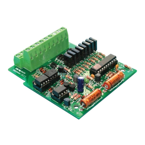
- Page 19 WD-34 | WD-34.2 | WD-34.M English Opto couplers OK1, OK4 6N136 OK2, OK3 PC817 (2 pieces) or PC827 (1 piece) IC-sockets 20-pole OK1, OK4, OK2/OK3 8-pole Double terminal strips 2 x 9-pole Solder pins 2-pole Fig.1 : PCB layout (WD-34)
- Page 20 English WD-34 | WD-34.2 | WD-34.M Assembly Proceed according to the order given in the list below. First solder the components on the solder side of the PCB and then cut the excess wires with the side cutter. Follow the instructions on soldering in section 3.
- Page 21 WD-34 | WD-34.2 | WD-34.M English Solder pins Transistors for a Observe the polarity! high power With transistors for a high power rating in TO rating packages (e.g. BD types) the unlabelled back side is marked in the PCB layout by a thick line.
-
Page 22: Connecting The Decoder
English WD-34 | WD-34.2 | WD-34.M 7. Connecting the decoder The decoder has terminal strips inserted to plug in and screw on the connecting wires for the solenoid accessories and the power supply. WD-34 WD-34.2 and WD-34.M Make the connections one after the other: ... -
Page 23: Pin Connections Turnout Decoder Wd-34
WD-34 | WD-34.2 | WD-34.M English 7.1. Pin connections turnout decoder WD-34 Turnout decoder WD-34 Solenoid accessory / turnout 2 "straight" Solenoid accessory / turnout 2 return conductor Solenoid accessory / turnout 2 "diverging" Solenoid accessory / turnout 4 "straight"... -
Page 24: Pin Connections Turnout Decoder Wd-34.2
English WD-34 | WD-34.2 | WD-34.M 7.2. Pin connections turnout decoder WD-34.2 Turnout decoder WD-34.2 Solenoid accessory / turnout 2 "diverging" or F2 = "on" Solenoid accessory / turnout 2 return conductor Solenoid accessory / turnout 2 "straight" or F2 = "off"... -
Page 25: Pin Connections Turnout Decoder Wd-34.M
WD-34 | WD-34.2 | WD-34.M English 7.3. Pin connections turnout decoder WD-34.M Turnout decoder WD-34.M Motor-run turnouts Solenoid accessories Motor-run turnout 2 Solenoid accessory / connection 1 turnout 2 "diverging" or F2 = "on" or F2 = "on" Solenoid accessory / turnout 2... - Page 26 English WD-34 | WD-34.2 | WD-34.M Turnout decoder WD-34.M Motor-run turnouts Solenoid accessories Motor-run turnout 1 Solenoid accessory / connection 1 turnout 1 "diverging" or F1 = "on" or F1 = "on" Solenoid accessory / not in use turnout 1 return conductor...
-
Page 27: Power Supply
WD-34 | WD-34.2 | WD-34.M English 7.4. Power supply You can supply the decoder either via the central unit or via a seperate transformer according to the two following diagrams. Power supply via central unit Caution: Switch off the central unit before connecting the decoder. -
Page 28: Connection Examples
English WD-34 | WD-34.2 | WD-34.M 7.5. Connection examples Connecting coil driven turnouts Connection of turnouts to terminals 4 to 6 ("turnout 4") Connecting decouplers Connection of two decouplers to terminals 4 to 6 Page 28... - Page 29 WD-34 | WD-34.2 | WD-34.M English Connecting motor driven turnouts to WD-34.M Connection of turnouts to terminals 4 and 6 ("turnout 4") Page 29...
-
Page 30: Programming The Decoder
When using a Motorola central unit you can set the decoder address with a programming jumper (WD-34) or with a programming push- button (WD-34.2 and WD-34.M). Changing the other decoder´s features or assigning a locomotive address is neither necessary in layouts run in Motorola format only nor possible with Motorola central units. - Page 31 WD-34 | WD-34.2 | WD-34.M English Name of CVs Input value Remarks and tips (Default) Decoder address 1, 2, 3, ... 63 NB: In addition, you have to 1 to 63 input the value "0" in CV#9. Decoder address 0, 1, 2, 3 ... 7...
- Page 32 In order to set the address via the programming jumper / push-button perform the following steps: 1. WD-34: Bridge the two pins of the programming connector JP1, by putting on the jumper included in the package. Take it away as soon as the LED flashes.
-
Page 33: Programming The Basic Features
(62) Read only! Reset 0 ... 255 Any input value restores the settings in state of delivery. 8.3. Programming the configuration data for the WD-34 Name of CVs CV Input value Remarks and tips (Default) On-time 0, 1, 2 ... 255... - Page 34 English WD-34 | WD-34.2 | WD-34.M Name of CVs CV Input value Remarks and tips (Default) Configuration 29 128, 136 RailCom off data 1 (136) RailCom on → WD-34 Configuration 29 0, 8, 128, 136 RailCom off data 1 (136) RailCom on →...
-
Page 35: Check List For Troubleshooting
Possible cause: Short circuit at one of the turnouts. à Check the turnouts. The external LED flashes (WD-34.2 only). Cause: The assigned turnouts have not been switched properly or were switched manually. à Check the turnouts. Assignment of the flashing sequences to the turnouts: 1 x flashing –... - Page 36 English WD-34 | WD-34.2 | WD-34.M After programming the address the decoder does not react to switching commands. Possible cause: When programming the decoder address via CV you set the decoder address. To switch the decoder accessory decoder addresses are used. à Input the accessory decoder address to switch.
-
Page 37: Guarantee Bond
WD-34 | WD-34.2 | WD-34.M English 10. Guarantee bond For this product we issue voluntarily a guarantee of 2 years from the date of purchase by the first customer, but in maximum 3 years after the end of series production. The first customer is the consumer first... -
Page 38: Eu Declaration Of Conformity
English WD-34 | WD-34.2 | WD-34.M 11. EU declaration of conformity This product conforms with the EC-directives mentioned below and is therefore CE certified. 2004/108/EG on electromagnetic. Underlying standards: EN 55014-1 and EN 61000-6-3. To guarantee the electromagnetic tolerance in operation you must take the following precautions: ... - Page 39 Information and tips: http://www.tams-online.de Warranty and service: Tams Elektronik GmbH Fuhrberger Straße 4 DE-30625 Hannover fon: +49 (0)511 / 55 60 60 fax: +49 (0)511 / 55 61 61 e-mail: modellbahn@tams-online.de...
Need help?
Do you have a question about the WD-34 and is the answer not in the manual?
Questions and answers