
Related Manuals for tams elektronik SD-34


Summary of Contents for tams elektronik SD-34
- Page 1 SD-34 | SD-34.2 4-fold Switching Decoder Manual SD-34 Item numbers 43-01345 43-01346 43-01347 SD-34.2 Item numbers 43-01356 43-01357 tams elektronik n n n...
- Page 2 © Tams Elektronik GmbH All rights reserved, in particular the right of reproduction, distribution and translation. Copies, reproductions and alterations in any form require the written permission of Tams Elektronik GmbH. We reserve the right to make technical changes. Printing the manual The formatting is optimised for double-sided printing.
-
Page 3: Table Of Contents
2. Operation overview.......................6 3. Assembling the SD-34 kit....................7 3.1. Safety instructions....................7 3.2. Soldering properly....................8 3.3. Preparation......................9 3.4. SD-34: PCB layout and parts list................11 3.5. Assembly......................13 3.6. Performing a visual check...................14 4. Connections.......................15 4.1. Pin connections accessory decoder SD-34............16 4.2. Pin connections accessory decoder SD-34.2............17 4.3. -
Page 4: Getting Started
1.1. Contents of the package Switching decoder SD-34: 1 kit SD-34 (item no. 43-01345-01), containing the components listed in the parts list ( section 3.4.) and one PCB or 1 ready-built and tested circuit board SD-34 (item no. 43-01346-01) or 1 switching decoder SD-34 in housing (item no. -
Page 5: Intended Use
SD-34 | SD-34.2 1.3. Intended use The switching decoder is intended for use in model construction, especially in model railway layouts, according to the specifications in the manual. Any other use is not in accordance with the intended use and will result in the loss of the warranty claim. Intended use also includes reading, understanding and following all parts of the instructions. -
Page 6: Operation Overview
SD-34.2 instead of turnout addresses. The 4 outputs of the decoder are switched via the function keys F1 to F4 then. This allows to use the SD-34.2 in combination with DCC control units not designed for controlling turnout addresses. Note: The changeover to the use of locomotive addresses is only possible with a DCC control unit. -
Page 7: Assembling The Sd-34 Kit
In schools, training centres, clubs and workshops, assembly must be supervised by qualified personnel. In industrial institutions, health and safety regulations applying to electronic work must be adhered to. Assembling the SD-34 kit | 7... -
Page 8: Soldering Properly
This can lead not only to malfunction, but also to the destruction of expensive components. You can re-liquefy excess solder with the clean hot soldering tip. The solder then flows from the board to the soldering tip. 8 | Assembling the SD-34 kit... -
Page 9: Preparation
Zener diodes are used for limiting voltages. In contrast to "normal" diodes they are not destroyed when the limit voltage is exceeded. The diode type is printed on the body. Assembling the SD-34 kit | 9... - Page 10 Modular terminal blocks Modular terminal blocks are solder-in screw-type terminals. They provide a solder-free and safe connection of the cables to the circuit, which can still be separated any time. 10 | Assembling the SD-34 kit...
-
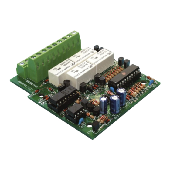
Page 11: Sd-34: Pcb Layout And Parts List
SD-34 | SD-34.2 3.4. SD-34: PCB layout and parts list PCB layout Assembling the SD-34 kit | 11... - Page 12 PC817 (2 pieces) or PC827 (1 piece) IC-sockets 20-pole OK1, OK4, OK2/OK3 8-pole Relays K1, K2, K3, K4 bistable 2 x Um 5 V Double modular 2 x 9-pole terminal blocks Pin header 2-pole 12 | Assembling the SD-34 kit...
-
Page 13: Assembly
Do not bend the "legs" when inserting them into the sockets. Check that the markings on the PCB, the socket and the IC show to the same direction. Assembling the SD-34 kit | 13... -
Page 14: Performing A Visual Check
Check that solder contacts which are close to each other are not unintentionally connected to each other. Risk of short circuit! Check that all components are polarised correctly. When you have remedied all faults, go on to the next part. 14 | Assembling the SD-34 kit... -
Page 15: Connections
SD-34 | SD-34.2 4. Connections The decoder is equipped with terminals into which you plug and screw the connecting cables for the solenoid accessories and the power supply. Make the connections one after the other: the accessories ... -
Page 16: Pin Connections Accessory Decoder Sd-34
SD-34 | SD-34.2 tams elektronik 4.1. Pin connections accessory decoder SD-34 Switching decoder SD-34 Switching contact 2, to be switched with "straight on" Switching contact 2, return conductor Switching contact 2, to be switched with "branching" Switching contact 4, to be switched with "straight on"... -
Page 17: Pin Connections Accessory Decoder Sd-34.2
SD-34 | SD-34.2 4.2. Pin connections accessory decoder SD-34.2 Switching decoder SD-34.2 Switching contact 2, to be switched with "branching" or F2 = "on" Switching contact 2, return conductor Switching contact 2, to be switched with "straight on" of F2 = "off"... -
Page 18: Connection To The Power Supply
SD-34 | SD-34.2 tams elektronik 4.3. Connection to the power supply You can supply the decoder and the connected servos and other consumers either with the digital voltage from the booster circuit, i.e. via the integrated booster of the digital central unit or a separate booster, ... -
Page 19: Connection Example
SD-34 | SD-34.2 4.4. Connection example Connection of a signal to terminals 4 to 6 ("switching contacts 4") Connections | 19... -
Page 20: Settings
(turnout commands). Setting the address with the jumper or push-button With Motorola central units the address can be set via the programming jumper (SD-34) or the programming push-button (SD-34.2) only. When using DCC central units it is often easier to set the address via the programming jumper / push-button than to program it via CV. - Page 21 In order to set the address via the programming jumper / push-button perform the following steps: 1. SD-34: Bridge the two pins of the programming connector JP1, by putting on the jumper included in the package. Take it away as soon as the LED flashes.
-
Page 22: Basic Settings
SD-34 | SD-34.2 tams elektronik 5.2. Basic settings Name of CVs Input value Remarks and tips (Default) Version Read only! Manufacturer (62) Read only! Reset 0 ... 255 Any input value restores the settings in state of delivery. 5.3. Configuration data... -
Page 23: Checklist For Troubleshooting And Error Correction
SD-34 | SD-34.2 6. Checklist for troubleshooting and error correction Warning: If you notice a strong heat development, immediately disconnect the connection to the supply voltage. Fire hazard! Possible causes: One or more connections are faulty. à Check the connections. -
Page 24: Technical Hotline
SD-34 | SD-34.2 tams elektronik 6.1. Technical Hotline If you have any questions about the use of the decoder, our technical hotline will help you (telephone number and e-mail address on the last page). 6.2. Repairs You can send us a defective decoder for inspection / repair (address on the last page). Please do not send us your return freight collect. -
Page 25: Technical Data
SD-34 | SD-34.2 7. Technical data Digital protocols Data formats Motorola DCC (according to NMRA and RCN standard) Adress range SD-34: Hint: The adress range to be used also MM: 1020 turnout addresses depends from the control unit. - Page 26 SD-34 | SD-34.2 tams elektronik Environment For use in closed rooms Ambient temperature during 0 ~ + 30 °C operation Permissible relative humidity 10 ~ 85% (non-condensing) during operation Ambient temperature during - 10 ~ + 40 °C storage Permissible relative humidity...
-
Page 27: Warranty, Eu Conformity & Weee
SD-34 | SD-34.2 8. Warranty, EU conformity & WEEE 8.1. Guarantee bond For this product we issue voluntarily a guarantee of 2 years from the date of purchase by the first customer, but in maximum 3 years after the end of series production. The first customer is the consumer first purchasing the product from us, a dealer or another natural or juristic person reselling or mounting the product on the basis of self-employment. -
Page 28: Eu Declaration Of Conformity
SD-34 | SD-34.2 tams elektronik 8.2. EU Declaration of Conformity This product fulfils the requirements of the following EU directives and therefore bears the CE marking. 2001/95/EU Product Safety Directive 2015/863/EU on the restriction of the use of certain hazardous substances in electrical and electronic equipment (RoHS) 2014/30/EU on electromagnetic compatibility (EMC Directive). - Page 29 SD-34 | SD-34.2...
- Page 30 SD-34 | SD-34.2 tams elektronik...
- Page 31 SD-34 | SD-34.2...
- Page 32 Further Information and Tips: http://www.tams-online.de Warranty and Service: tams elektronik GmbH Fuhrberger Str. 4 30625 Hannover / GERMANY Phone: +49 (0)511 / 55 60 60 Fax: +49 (0)511 / 55 61 61 Email: s upport@tams-online.de...
Need help?
Do you have a question about the SD-34 and is the answer not in the manual?
Questions and answers