
Related Manuals for tams elektronik WD-34.BiDiB


Summary of Contents for tams elektronik WD-34.BiDiB
- Page 1 Manual 4-fold Turnout Decoders WD-34.BiDiB Item no. 46-12356 | 46-12357 WD-34.M.BiDiB Item no. 46-12366 | 43-12367 tams elektronik n n n...
- Page 2 English WD-34.BiDiB | WD-34.M.BiDiB © 12/2019 Tams Elektronik GmbH All rights reserved. No part of this publication may be reproduced or transmitted in any form or by any means, electronic or mechanical, including photocopying, without prior permission in writing from Tams Elektronik GmbH.
-
Page 3: Table Of Contents
3.3. Use in BiDiBus..............10 3.4. Wiring................12 3.5. Assignment in the BiDiBus system (addressing)....12 4. Technical specifications..............13 5. Connecting the decoder.............15 5.1. Pin connections WD-34.BiDiB..........16 5.2. Pin connections WD-34.M.BiDiB...........17 5.3. Power supply..............19 5.4. Connection examples............20 5.5. Connection to the BiDiBus...........21 6. Settings..................22 6.1. -
Page 4: Getting Started
Intended use The turnout decoders WD-34.BiDiB and WD-34.M.BiDiB are designed to be operated according to the instructions in this manual in BiDiB- controlled model railway layouts. Any other use is inappropriate and invalidates any guarantees. - Page 5 In order to connect the module you need wire. Recommended cross- sections: > 0,25 mm² for all connections. WD-34.BiDiB only: When using motor-run turnouts, you need an additional adapter AMW-1 or AMW plus for each turnout (item-no. 72-00076 or 72-00176).
-
Page 6: Safety Instructions
English WD-34.BiDiB | WD-34.M.BiDiB 2. Safety instructions Caution: The decoder contains integrated circuits. These are very sensitive to static electricity. Do not touch components without first discharging yourself. Touching a radiator or other grounded metal part will discharge you. Mechanical hazards Cut wires can have sharp ends and can cause serious injuries. - Page 7 WD-34.BiDiB | WD-34.M.BiDiB English After condensation build up, allow a minimum of 2 hours for dispersion. Use only original spare parts if you have to repair the kit or the ready-built module. Other dangers Children can cause any of the accidents mentioned above because they are inattentive and not responsible enough.
-
Page 8: Operation Overview
It complies with the requiremets for the class "Accessory Control" defined in the BiDiB-specification. Note: The WD-34.BiDiB cannot be controlled by digital control units sending digital accessory decoder commands to the accessory decoders (e.g. in Motorola or DCC format). -
Page 9: Features According To The Bidib-Specification
In case problems occur during the operation (e.g. short circuit) the decoder automatically sends an error message. In addition to the obligatory features the points decoder WD-34.BiDiB has the following optional features: Monitoring and spontaneous message (WD-34.BiDiB only) In combination with points with limit stop the points decoder WD- 34.BiDiB can identify and report the actual position of points. -
Page 10: Use In Bidibus
English WD-34.BiDiB | WD-34.M.BiDiB After the set on-time has elapsed the decoder WD-34.BiDiB compares the actual position of points with limit stop with the position they should have according to the operation command. Firmware update It is possible to update the firmware of the WD-34.(M.)BiDiB. - Page 11 WD-34.BiDiB | WD-34.M.BiDiB English Page 11...
-
Page 12: Wiring
English WD-34.BiDiB | WD-34.M.BiDiB 3.4. Wiring According BiDiBus specification patch cables with RJ 45 connectors (Cat5 cables) are used as bus lines for the points decoder WD-34.(M.)BiDiB. These cables allow simple and quick handling and provide safe connections to the interface and other nodes. -
Page 13: Technical Specifications
WD-34.BiDiB | WD-34.M.BiDiB English 4. Technical specifications Features according to the Node, class "Accessory Control" BiDiB-specification Optional Features: adjustable on-time: 100 msec - 127 sec. Firmware update Additional optional features monitoring of the actual position of of the WD-34.BiDiB points (with points with limit stop) (not with WD-34.M.BiDiB) - Page 14 Dimensions of the PCB / approx. 72 x 82 mm / including housing approx.100 x 90 x 35 mm Weight of the assembled WD-34.BiDiB: approx. 45 g / 93 g board / including housing WD-34.M.BiDiB: approx. 49 g / 97 g Page 14...
-
Page 15: Connecting The Decoder
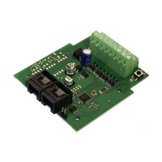
WD-34.BiDiB | WD-34.M.BiDiB English 5. Connecting the decoder On one side, the decoder has terminal strips inserted to plug in and screw on the connecting wires for turnouts and/or solenoid accessories and the power supply. On the other side the decoder has two RJ 45 connection sockets for the connection to the BiDiBus. -
Page 16: Pin Connections Wd-34.Bidib
English WD-34.BiDiB | WD-34.M.BiDiB 5.1. Pin connections WD-34.BiDiB Turnout decoder WD-34.BiDiB Solenoid accessory / turnout 1 "diverging" Solenoid accessory / turnout 1 return conductor Solenoid accessory / turnout 1 "straight " Solenoid accessory / turnout 3 "diverging" Solenoid accessory / turnout 3 return conductor Solenoid accessory / turnout 3 "straight "... -
Page 17: Pin Connections Wd-34.M.bidib
WD-34.BiDiB | WD-34.M.BiDiB English 5.2. Pin connections WD-34.M.BiDiB Turnout decoder WD-34.M.BiDiB Motor-run turnouts Solenoid accessories Motor-run turnout 1 Solenoid accessory / turnout 1 connection 1 "diverging" Solenoid accessory / turnout 1 not in use return conductor Motor-run turnout 1 Solenoid accessory / turnout 1 connection 2 "straight"... - Page 18 English WD-34.BiDiB | WD-34.M.BiDiB Turnout decoder WD-34.M.BiDiB Motor-run turnouts Solenoid accessories Motor-run turnout 2 Solenoid accessory / turnout 2 connection 1 "diverging" Solenoid accessory / turnout 2 not in use return conductor Motor-run turnout 2 Solenoid accessory / turnout 2 connection 2 "straight"...
-
Page 19: Power Supply
WD-34.BiDiB | WD-34.M.BiDiB English 5.3. Power supply As a power supply for the decoder and the connected solenoid accessories and/or turnouts you need an AC voltage transformer (12–18 V ~) or a DC voltage power pack (14–24 V =). Caution: You can use one transformer or powerpack to supply several BiDiB nodes. -
Page 20: Connection Examples
English WD-34.BiDiB | WD-34.M.BiDiB 5.4. Connection examples Connecting coil driven turnouts Connection of points to terminals 13 to 15 ("points 4") Connecting decouplers Connection of two decouplers to terminals 13 to 15 Page 20... -
Page 21: Connection To The Bidibus
WD-34.BiDiB | WD-34.M.BiDiB English Connecting motor driven turnouts to WD-34.M.BiDiB Connection of turnouts to terminals 4 and 6 ("turnout 4") 5.5. Connection to the BiDiBus The two RJ 45 connection sockets are connected in parallel and thus can be used optionally for the connection of the decoder to the BiDiB interface and/ or other BiDiB nodes on the same level. -
Page 22: Settings
English WD-34.BiDiB | WD-34.M.BiDiB 6. Settings When switching on the BiDiB system all nodes are identified automatically by the interface. As far as supported by the control software, all new nodes that have not been configurated, are displayed when switching on and can be configurated immediately afterwards. - Page 23 WD-34.BiDiB only: Identifying and reporting of the actual position of points The configuration is valid for all points connected to the WD-34.BiDiB. In state of the delivery the function is switched on (for use with points with limit stop). If points without limit stop are connected, the function has to be switched off.
-
Page 24: Check List For Troubleshooting
English WD-34.BiDiB | WD-34.M.BiDiB 7. Check list for troubleshooting Parts are getting too hot and/or start to smoke. Disconnect the system from the mains immediately! Possible cause: One or several connections are faulty. à Check the connections. If the in- or outputs of the decoder have been connected to live cables the decoder usually is damaged beyond repair. - Page 25 WD-34.BiDiB | WD-34.M.BiDiB English Hotline If problems with your decoder occur, our hotline is pleased to help you (mail address on the last page). Repairs You can send in a defective decoder for repair (address on the last page). In case of guarantee the repair is free of charge for you. With damages not covered by guarantee, the maximum fee for the repair is 50 % of the current sales price according to our valid price list.
-
Page 26: Guarantee Bond
English WD-34.BiDiB | WD-34.M.BiDiB 8. Guarantee bond For this product we issue voluntarily a guarantee of 2 years from the date of purchase by the first customer, but in maximum 3 years after the end of series production. The first customer is the consumer first... -
Page 27: Eu Declaration Of Conformity
WD-34.BiDiB | WD-34.M.BiDiB English 9. EU declaration of conformity This product conforms with the EC-directives mentioned below and is therefore CE certified. 2004/108/EG on electromagnetic. Underlying standards: EN 55014-1 and EN 61000-6-3. To guarantee the electromagnetic tolerance in operation you must take the following precautions: ... - Page 28 Information and tips: http://www.tams-online.de Warranty and service: Tams Elektronik GmbH Fuhrberger Straße 4 DE-30625 Hannover fon: +49 (0)511 / 55 60 60 fax: +49 (0)511 / 55 61 61 e-mail: modellbahn@tams-online.de...
Need help?
Do you have a question about the WD-34.BiDiB and is the answer not in the manual?
Questions and answers