Table of Contents
Advertisement
Quick Links
*FASTUS is a product brand of OPTEX FA.
C-MOS Laser Displacement Sensor
CD2H Series
User's Manual
Before using this product, read this manual carefully.
Keep this manual at hand so that it can be used whenever necessary.
Store the manual in a secure location.
OPTEX FA CO., LTD.
Ramco Innovations 800-280-6933
www.ramcoi.com
nsales@ramcoi.com
Advertisement
Table of Contents

Related Manuals for OPTEX FA Fastus CD2H Series


Summary of Contents for OPTEX FA Fastus CD2H Series
- Page 1 *FASTUS is a product brand of OPTEX FA. C-MOS Laser Displacement Sensor CD2H Series User’s Manual Before using this product, read this manual carefully. Keep this manual at hand so that it can be used whenever necessary. Store the manual in a secure location.
-
Page 3: Introduction
Introduction Thank you for purchasing this C-MOS Laser Displacement Sensor CD2H Series. Before using this product, please read this user’s manual carefully to ensure proper use. Read this manual thoroughly, and then keep this manual at hand so that it can be used whenever necessary. Introduction Ramco Innovations 800-280-6933 www.ramcoi.com... -
Page 4: Safety Precautions
Safety Precautions Safety precautions for ensuring safe operation of the C-MOS Laser Displacement Sensor CD2H Series are displayed as follows with the following symbols. Precautions listed here describe important information about safety. Make sure to follow them accordingly. Safety Symbols „... - Page 5 Failure to do so may cause a fire. Repairing the product is dangerous and should in no way be performed by the customer. Contact an OPTEX FA sales representative for repairs. Safety Precautions...
- Page 6 Warning What to do if water enters the product If water or any other liquid enters the product or the cable, immediately stop operating the product and turn off the power. Using the product in this condition may cause a fire. Caution •...
- Page 7 • Before using this product, fully examine the applicable environmental laws and regulations, and operate the product in conformity to such laws and regulations. OPTEX FA does not assume any responsibility for damages or losses occurring as a result of noncompliance with applicable laws and regulations.
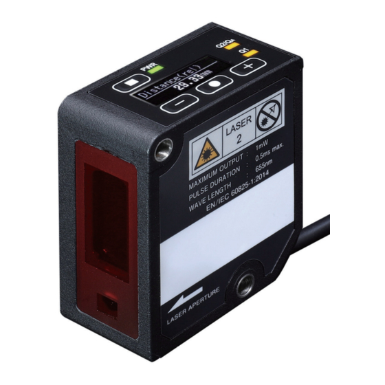
- Page 8 IEC 60825-1 Ed. 3., as described Do not look directly at the beam in Laser Notice No. 56, dated May 8, 2019 OPTEX FA CO., LTD. 91 Chudoji-Awata-cho Shimogyo-ku Kyoto 600-8815 JAPAN Place of manufacture : OF...
-
Page 9: Expressions Used In This Manual
Expressions Used in This Manual This section explains the expressions used in this manual. Note Indicates an item that requires special attention during operation MEMO Indicates information that is useful to know during operation Included display images „ Note that display images included in this user’s manual are subject to change without prior notice due to product improvements. -
Page 10: Table Of Contents
Contents Introduction .......................... i Safety Precautions ......................ii Expressions Used in This Manual ..................vii Product Overview Included Items ......................1-2 Options .................... 1-2 1-1-1 Part Names and Functions ...................1-3 Mounting the Sensor .....................1-4 I/O Circuit Diagrams .....................1-7 Power On Settings ....................1-8 Operation Examples for Major Applications ............1-9 1-6-1 Setting the Current Measured Value to Zero ........ - Page 11 2-1-7 Mode ....................2-9 2-1-8 Recording ..................2-9 2-1-9 [Reference] Status Icons ............... 2-10 Settings Menu [A] Measurement ....................3-2 3-1-1 Basic Key Operations for Configuring Settings ....... 3-2 [A1] Sampling period ............... 3-3 3-1-2 [A2] Moving average ............... 3-4 3-1-3 [A3] Median filter ................
- Page 12 [C] Output 2/Analog Output (DO2/AO) Settings ..........3-23 3-3-1 Key Operations for Configuring Settings ........3-23 3-3-2 [C1] Output2 Mode ................ 3-25 3-3-3 [C31] Analog Teach 4mA Auto / [C32] Analog Teach 20mA Auto ..3-25 3-3-4 [C36] Analog Teach 0V Auto / [C37] Analog Teach 10V Auto ..3-25 3-3-5 [C33] Analog Teach 4mA Manual / [C34] Analog Teach 20mA Manual ...................
- Page 13 3-5-6 [E7] No of decimal places ............. 3-43 3-5-7 [E11] Display off time ..............3-43 3-5-8 [E12] Display brightness ............... 3-43 3-5-9 [E13] Rotate display ..............3-43 3-5-10 [E16] Laser ..................3-44 3-5-11 [E17] Output NPN/PNP/PP ............3-44 [F] Information .....................3-45 3-6-1 Key Operations for Configuring Settings ........
- Page 14 CD2H_URES_Navigator ..................4-22 4-6-1 Functions of CD2H_URES_Navigator .......... 4-22 4-6-2 System configuration for CD2H_URES_Navigator ....... 4-22 4-6-3 Connecting ..................4-23 Specifications Specifications ......................5-2 Measurement Specifications ............5-2 5-1-1 Common Specifications ..............5-2 5-1-2 Dimensions ......................5-5 Typical Characteristics ..................5-7 Spot Size ..................5-7 5-3-1 5-3-2 Interference Area ................
-
Page 15: Product Overview
Product Overview This chapter provides an overview of the product. -
Page 16: Included Items
1-1 Included Items Sensor ×1 Instruction manual ×1 M4×35 mm mounting screws ×2 Washers, M4 nuts ×2 sets 1-1-1 Options M12 5-pin straight open-end cables: • YF2A15-020VB5XLEAX: 2 m • YF2A15-050VB5XLEAX: 5 m • YF2A15-100VB5XLEAX: 10 m Minimum bending radius: 26 mm (stationary position) Mounting bracket M12 5-pin straight open-end bending resistant cables: BEF-WN-OD2000-B... -
Page 17: Part Names And Functions
1-2 Part Names and Functions Control output DO2 / analog output AO indicator (orange) Display Control output DO1 indicator (orange) Power indicator (green) RETURN key “+” key SET key “-” key Mounting holes (ø4.5 mm) * Tightening torque: 0.8 N·m or less Light receiving window Light emitting window Name... -
Page 18: Mounting The Sensor
1-3 Mounting the Sensor Note Take care to observe the following when handling the sensor head cable. Excessive stress on the cable may lead to breakage. • Do not pull on the cable with a force of 30 N or more. 30 mm or larger •... - Page 19 To ensure high detection accuracy and stability, mount the sensor as shown for the applicable target. With height differences With material/color differences With rotating measurement targets Mounting the Sensor Ramco Innovations 800-280-6933 www.ramcoi.com nsales@ramcoi.com...
- Page 20 With holes or recesses When mounted on a wall Attach the sensor head so that the detection side (emitting/receiving surfaces) is parallel to the detection target. Adjust the installation so that the spot aligns with the detection position, and check whether the Control output DO2 / analog output AO indicator (orange) lights up (default setting).
-
Page 21: I/O Circuit Diagrams
1-4 I/O Circuit Diagrams SIO mode (standard I/O mode) with the NPN setting SIO mode (standard I/O mode) with the PNP setting ➀ ➀ Brown: 18 to 24 V DC Brown: 18 to 24 V DC ➃ Black: Control output ➃... -
Page 22: Power On Settings
1-5 Power On Settings When the power is first turned on, “Initial Setting” will be displayed. Select the display language and control output type to proceed. The information provided in this user’s manual is based on the display language being set to “English.” “Initial Setting”... -
Page 23: Operation Examples For Major Applications
1-6 Operation Examples for Major Applications 1-6-1 Setting the Current Measured Value to Zero Setting the display to zero using the keys on sensor „ RUN mode Distance(rel.) XXX.Xmm Press and hold the key for 2 seconds. Press the + or - key to SET Zero point teach SET Zero point teach change the highlighted item. -
Page 24: Using Analog Current Output (4 To 20 Ma)
“Trigger on” selected as the input mode D 1 Input Function When NPN output is selected: Zero point teach The external input wire (gray wire) and ground wire (blue wire) are short-circuited, and the current value is set as zero. The displayed item will be highlighted. -
Page 25: Using Analog Voltage Output (0 To 10 V)
1-6-3 Using Analog Voltage Output (0 to 10 V) Change the analog output setting from the default setting to analog voltage output. The white wire can be used for positive analog, and the blue wire can be used for ground (same as power supply ground). -
Page 26: Using Control Outputs
Default settings for each analog voltage output type CD2H-30xxxA CD2H-50xxxA CD2H-245xxx CD2H-350xxx CD2H-700xxx -5 mm -10 mm -175 mm -250 mm -500 mm (25 mm from sensor) (40 mm from sensor) (70 mm from sensor) (100 mm from sensor) (200 mm from sensor) 10 V +5 mm +10 mm... - Page 27 DO2 (Output 2) is set to analog current output by default, but the control output can be changed in the same way as DO1. Control output can also be output separately for DO1 and DO2. RUN mode Distance(rel.) Measurement XXX.Xmm + key Distance(bar) - key...
- Page 28 Operation Examples for Major Applications 1-14...
-
Page 29: Main Menu
Main Menu Up to six menus can be accessed from the main menu, by pressing the + or - key. Press the z key on one of these six menus to enter the advanced settings mode. -
Page 30: Switching The Main Menu
2-1 Main Menu After “Initial Setting” (setting the display language and control output), “Distance(rel.)” is used as the main display. 2-1-1 Switching the Main Menu Press the + or - key to switch between up to six different displays as shown below. Press the z key in any display to enter the advanced settings mode. - Page 31 RUN mode Displayed after completing “Initial Setting” or when the power is turned on. Distance(rel.) The measurement center will be set as zero, and near-side measurements will be XXX.Xmm displayed with “-” while far-side measurements will be displayed with “+.” Press and hold key for - key...
- Page 32 - key + key Displays the measured value as a bar graph. Distance(bar) The Output 1 (DO1) and Output 2 (DO2) threshold setting ranges are also displayed. Press and hold key for - key + key 2 seconds. Received light waveforms +/- keys Moves the display area.
-
Page 33: Recording
2-1-2 Recording Displays various analysis results of sampled measurement values from start to stop. Press and hold Press the key to start Press the key to key for recording. stop recording. 2 seconds. Recording Recording Min. value Start Stop XXX.Xmm “Start”... -
Page 34: Measured Value Display (Absolute Value)
2-1-4 Measured Value Display (Absolute Value) Press and hold the „ key for 3 seconds from Distance “Distance(rel.)” to display the distance from the sensor to the object being measured. After 30 353.06mm seconds, the display will return to the “Distance(rel.)”... -
Page 35: Measured Value Display (Bar)
2-1-5 Measured Value Display (Bar) Press the + key once (twice when set to edge Distance(bar) detection) from “Distance(rel.)” to display the measured value and the specific control output range in a bar graph. (1) Press and hold the z key for 3 seconds to Remarks: view the received light waveform. -
Page 36: Analog Value
2-1-6 Analog value Press the + key twice (3 times when set to edge Analog value mode) from “Distance(rel.)” to display the current analog value (V/mA) when Output2 Mode (DO2/ 15.265mA AO) is set to “Analog output.” Remarks: Analog value Not displayed if “Analog output”... -
Page 37: Mode
2-1-7 Mode Press the + key 2 to 4 times (depending on the Mode setting) from “Distance(rel.)”. Select from “Customized,” “Precision,” or Customized “Speed.” This will enable the simple setting mode for measurement settings for each application. (1) Press and hold the z key for 3 seconds to Detailed settings for each mode switch to SET Mode. -
Page 38: Reference] Status Icons
2-1-9 [Reference] Status Icons An arrow icon will appear in the upper-right Distance(rel.) corner of the display when the zero point teach is enabled. 1999.90mm The icon will be displayed on “Distance(rel.),” “Distance(bar),” and “Analog value”. The arrow icon will disappear if the zero point teach is released. -
Page 39: Settings Menu
Settings Menu (Press the z key at the main menu to enable the setting mode.) This chapter explains how to use the settings menu. -
Page 40: A] Measurement
3-1 [A] Measurement Use this menu to configure measurement-related settings such as the sampling period, moving average, and median filter. Configured settings are applied to both DO1 (Output 1) and DO2 (Output 2). 3-1-1 Basic Key Operations for Configuring Settings Procedure „... -
Page 41: A1] Sampling Period
Number-based changes „ Measured value offset / Mask near / Mask far / Error mode / Error hold time Select one of the above setting items and press the key. A 7 Measured value offset 0.0mm The leftmost digit will be highlighted. A 7 Measured value offset 0000.0mm A 7 Measured value offset... -
Page 42: A2] Moving Average
3-1-3 [A2] Moving average Performs averaging for the measured values. The process is performed on median-filtered results. This results in smoother changes in measured values, but processing the measured value takes longer as more measurements are performed. During startup or alarm recovery, the moving average is performed using previously accumulated values until the specified number of measured values have been accumulated. -
Page 43: A3] Median Filter
3-1-4 [A3] Median filter Cuts off sudden changes in measured values to help reduce variations. The median value of the measured values within the set measurement count is used as the definite value. Using this in combination with the moving average should help stabilize measurement. •... -
Page 44: A7] Measured Value Offset
3-1-6 [A7] Measured value offset Stores the offset amount so that the measured value (relative) becomes zero during offset operation. Resetting the offset will set the offset value to 0 (zero). The offset value will be updated during each offset operation. Offset values can also be entered manually as desired. -
Page 45: A16] Error Mode
3-1-8 [A16] Error mode Sets the behavior when an alarm occurs (when no measurement data is available or when measurement is not possible). • Default value: Clamp value Clamp value The measured value becomes the set clamp value while the alarm is detected. This setting specifies how the measured value should be displayed when measurement is not possible. -
Page 46: A17] Set Clamp Value
3-1-9 [A17] Set clamp value Sets the value to be displayed when an alarm occurs (when no measurement data is available or when measurement is not possible). The value specified here will be displayed when “Clamp value” is selected. • Setting range: -2000.0 to +2000.0 mm •... -
Page 47: B] Output 1 (Do1) Settings
3-2 [B] Output 1 (DO1) Settings Use this setting to configure Output 1 settings, such as the output mode, threshold setting, and delay timer. 3-2-1 Key Operations for Configuring Settings Procedure „ RUN mode Press the key. Distance(rel.) 150.1mm A Measurement Press the + or - key to highlight “Output 1.”... - Page 48 Number-based changes „ DO1 Teach 1 Manual / DO1 Teach 2 Manual / DO1 Edge Max. / DO1 Edge Min. / DO1 Cycle offset / DO1 Timer set / DO1 Hysteresis / DO1 Tolerance Select one of the above settings and press the key.
-
Page 49: B1] Output1 Mode
3-2-2 [B1] Output1 Mode Sets how detection should be performed for the measured value. This setting defines the relationship between the threshold or hysteresis and output. DO1 1 point „ Output 1 turns off at a position at a distance equivalent to hysteresis from the position set through teaching or by the threshold. - Page 50 DO1 FGS2 „ DO1 Control Output 1 turns off within an area equivalent to the tolerance set centered on the Teach 1 Manual position (when “Near On” is selected for the output mode). Operation will be suspended for the set hysteresis amount during operation with output turned off. Teach 1 Manual Sensor measurement...
- Page 51 DO1 Edge „ This function is used in the following situations. • When sudden changes are detected • When the reference position changes in waves, making setting thresholds difficult Example: • Booklet counting • Peak/valley edge mode Edge measurement value The difference between the current measured value and the measured value before the cycle offset count becomes the edge measurement value.
- Page 52 Measurement object (example) Overview diagram of edge mode Cycle offset count (Time conversion = Sampling period × Cycle offset count) ① Current value ② Value delayed for cycle offset count Judgment value = ① Current value - ② Value delayed for cycle offset count Edge Max.
- Page 53 Booklet count settings example Measurement object (booklet) Example detection conditions • Line speed = Approx. 100 mm/sec • Sampling period = 0.5 ms • Moving average = 1 count • Median filter = Off • Narrowest edge spacing = Approx. 5 mm •...
-
Page 54: B6] Do1 Teach 1 Auto / [B7] Do1 Teach 2 Auto
Edge hold behavior for example edge measurement values Edge Max. Edge measured value (hold) Edge Max. No hold operation is performed for edge measurement values (hold off), and values are displayed as a gray dashed line. Variations in the actual conveyor surface level will likely affect the edge measurement value. We strongly recommend conducting trial operation under various circumstances when considering using this function. -
Page 55: B8] Do1 Teach 1 Manual / [B9] Do1 Teach 2 Manual
3-2-4 [B8] DO1 Teach 1 Manual / [B9] DO1 Teach 2 Manual 1 point „ Edits and writes the value written using Teach 1 Auto or the existing setting value. Zone „ Edits and writes the value written using Teach 1 Auto or Teach 2 Auto or the existing setting value. * Supplementary information: This setting can be configured when either (Teach 1 Auto/Teach 1 Manual) <... -
Page 56: B13] Do1 Switch Direction
3-2-7 [B13] DO1 Switch direction Sets the change direction of the measured value for edge mode. Changing the measurement direction will reverse this setting. • Positive: Detection is performed only when the measured value changes positively (rising edge detection). • Negative: Detection is performed only when the measured value changes negatively (falling edge detection). -
Page 57: B16] Do1 Output Mode
3-2-9 [B16] DO1 Output mode The following figure shows the changes in on/off statuses for each setting. Sets the output operation polarity. This function is similar to light on/dark on switching. • Near On: Turns the output on at the side nearest the threshold or within the range of Teach 1 Manual and Teach 2 Manual. -
Page 58: B17] Do1 Delay Timer
FGS2 „ Sensor Teach 1 Manual measurement range Tolerance Tolerance Output ON Near On Output OFF Output ON Far On Output OFF 3-2-10 [B17] DO1 Delay timer Selects the delay function. • Off: The control output is turned on when the judgment is turned on. •... -
Page 59: B18] Do1 Timer Set
3-2-11 [B18] DO1 Timer set Sets the delay time. For one-shot operation, this setting becomes the ON time instead of the delay time. * Individual delay times cannot be set for On/Off delay operation. * Turn off the delay function to set a delay time of 0 ms. Setting range: 1 to 30,000 ms Timing chart: Difference in on/off operation according to the „... -
Page 60: B19] Do1 Hysteresis
3-2-12 [B19] DO1 Hysteresis When the measured value approaches the threshold value (upper or lower), the control output may turn on/ off repeatedly (chattering). This condition can be prevented by providing a range of values at which the output should be turned on and then off after the threshold is exceeded. -
Page 61: C] Output 2/Analog Output (Do2/Ao) Settings
3-3 [C] Output 2/Analog Output (DO2/ AO) Settings Use this setting to configure Output 2 settings such as analog output, control output, threshold setting, and delay timer. 3-3-1 Key Operations for Configuring Settings Procedure „ RUN mode Distance(rel.) Press the key. - Page 62 Analog Teach 0V Auto Press the + or - key to select the setting item to be edited, such as “Analog Teach 0V Auto,” or “Analog Teach 10V Auto.” 220.0mm Press the key to edit the selected setting item, and when finished, press the key to confirm.
-
Page 63: C1] Output2 Mode
3-3-2 [C1] Output2 Mode The following can also be set for Output 2/Analog output (DO2/AO) in addition to the control output set for DO1. • Analog output settings (“Analog 4…20mA” or “Analog 0…10V.”) • Output 1 (DO1) inversion Other control output settings can be configured similar to DO1 control output 1. (See ʺ[B] Output 1 (DO1) Settingsʺ... -
Page 64: C33] Analog Teach 4Ma Manual / [C34] Analog Teach
3-3-5 [C33] Analog Teach 4mA Manual / [C34] Analog Teach 20mA Manual 3-3-6 [C38] Analog Teach 0V Manual / [C39] Analog Teach 10V Manual Edits and writes the threshold value written using teaching or the existing setting value as desired. (The analog output range cannot be set to less than 10% of the measurement range.) See ʺNumber-based changesʺ... - Page 65 Relationship between offset and analog output range „ The offset position results in an area being outside the analog output range. In these examples, measurement continues on the sensor display, but analog output is outside the output range. Analog current output (CD2H-350 with an absolute value offset of 500 mm) (mA) Measurement range Measurement range...
- Page 66 Relationship between analog output range setting and analog „ output (The figure below uses the CD2H-350 as an example.) • Analog output current (4…20mA) selected for Output 2/Analog output (DO2/AO) • When “-100” is input for “Analog Teach 4mA Manual,” and “100” is input for “Analog Teach 20mA Manual” Even though measurement is being performed on the sensor display, analog output will not change from 21 mA.
- Page 67 Offset operation and analog output after changing analog output „ setting range If offset operation is performed after changing the analog output setting range, the offset point will be set to the median value of analog output. Example: (1) Analog output behavior when “-50mm” is input for “Analog Teach 4mA Manual” and “150mm” is input for “Analog Teach 20mA Manual”...
-
Page 68: C6] Do2 Teach 1 Auto / [C7] Do2 Teach 2 Auto
3-3-7 [C6] DO2 Teach 1 Auto / [C7] DO2 Teach 2 Auto The settings for “[B6] DO1 Teach 1 Auto / [B7] DO1 Teach 2 Auto” (page 3-16) can also be used for DO2 (Output 2). 3-3-8 [C8] DO2 Teach 1 Manual / [C9] DO2 Teach 2 Manual The settings for “[B8] DO1 Teach 1 Manual / [B9] DO1 Teach 2 Manual”... -
Page 69: C17] Do2 Delay Timer
3-3-14 [C17] DO2 Delay timer The settings for “[B17] DO1 Delay timer” (page 3-20) can also be used for DO2 (Output 2). 3-3-15 [C18] DO2 Timer set The settings for “[B18] DO1 Timer set” (page 3-21) can also be used for DO2 (Output 2). 3-3-16 [C19] DO2 Hysteresis The settings for “[B19] DO1 Hysteresis”... - Page 70 Output 1 (DO1) and Output 2/Analog output (DO2/AO) detection „ mode setting parameters Output 1, Output 2 Output 2 only Light level Analog Analog Output 1 1 point Zone FGS2 Edge measurement error 4…20mA 0…10V inversion Output 2 Teach 4mA Auto Output 2 ...
-
Page 71: D] Input
3-4 [D] Input Used to configure various external input settings (teach input, hold input, offset input, etc.). 3-4-1 Key Operations for Configuring Settings Procedure „ RUN mode Press the key. Distance(rel.) 150.1mm Press the + or - key to highlight “Input.” C Output 2/Analog Press the key to edit “Input.”... -
Page 72: D1] Input Function
3-4-2 [D1] Input Function Sets the operation of external input. • Off: External input is not used (disabled). • Multi operations: Operation is performed using the following functions according to the input time. Input time 500 to 1000 ms: Laser off input OFF (Laser on) 1000 to 1500 ms: Laser off input ON (Laser off) 1500 to 2000 ms: Output 1 (DO1) Teach 1 Auto 2000 to 2500 ms: Output 1 (DO1) Teach 2 Auto... - Page 73 • Input Hold Mode: Select when using various hold functions. When “Hold” is selected for the “Input Function,” the Hold Selection menu will be displayed. (Select from “Measured value,” “Peak value,” “Lowest value,” “Peak-to-peak value,” “Auto peak value,” “Auto lowest value,” “Average value,” or “Normal.”) Use the input terminal as hold input or hold reset input.
-
Page 74: D2] Input Hold Mode
3-4-3 [D2] Input Hold Mode Sets various hold operations for the measured value. • Measured value: When “Trigger on” is selected as the input mode, the external input (hold input) rising edge measured value is output. When “Trigger off” is selected as the input mode, the external input (hold input) falling edge measured value is output. - Page 75 • Lowest value: When “Trigger on” is selected as the input mode, the maximum value while the external input (hold input) is off is displayed and held as the next rising edge. When “Trigger off” is selected as the input mode, the maximum value while the external input (hold input) is on is displayed and held as the next falling edge.
- Page 76 • Auto peak value: Automatically updates the peak value. When “Trigger on” is selected as the input mode, the value is reset to the current value at the rising edge of the external input (hold reset input). When “Trigger off” is selected as the input mode, the value is reset to the current value at the falling edge of the external input (hold reset input).
- Page 77 • Average value: When “Trigger on” is selected as the input mode, the average value while the external input (hold input) is off is displayed and held as the next rising edge. When “Trigger off” is selected as the input mode, the average value while the external input (hold input) is on is displayed and held as the next falling edge.
-
Page 78: D4] Input Delay
3-4-4 [D4] Input delay Operates as an input when the input continues for longer than the delay time (100 ms) when input delay is enabled. This function prevents external inputs from turning on/off at high speed. • No: Input delay OFF •... -
Page 79: E] Device
3-5 [E] Device Configures various device settings (initialization, display language, no. of decimal places, inverted display, etc.). 3-5-1 Key Operations for Configuring Settings Procedure „ RUN mode Press the key. Distance(rel.) 150.1mm Press the + or - key to highlight “Device.” Device Press the key to edit “Device.”... -
Page 80: E1] Reset Factory Settings
3-5-2 [E1] Reset factory settings Initializes the device and restores factory settings. • Yes: Perform initialization. • No: Cancels initialization. After resetting the device to factory settings, “Initial Setting” immediately begins. The setup procedure is as follows. (1) Press the z key to access language selection. “(Language English)” is displayed. (2) Press the z key to change the language. -
Page 81: E7] No Of Decimal Places
3-5-6 [E7] No of decimal places Sets the number of decimal places to display. • 0: No decimal place • 0.1: First decimal place • 0.01: Second decimal place The selection choices vary depending on the model (distance). • CD2H-30xxxA/CD2H-50xxxA: Select from 0, 0.1, 0.01, or 0.001. •... -
Page 82: E16] Laser
3-5-10 [E16] Laser Manually turns the laser on or off. • On: Turns the laser on. • Off: Turns the laser off. 3-5-11 [E17] Output NPN/PNP/PP Switches the output type between PNP/NPN and Push-pull. • PNP: Operates in PNP. • NPN: Operates in NPN. -
Page 83: F] Information
3-6 [F] Information Displays information about the device. 3-6-1 Key Operations for Configuring Settings Procedure „ RUN mode Press the key. Distance(rel.) 150.1mm Press the + or - key to highlight “Information.” Device Press the key to access the “Information” menu. (“Model number” will be displayed.) Information F 1 Model number 0000... -
Page 84: F3] Firmware Version
3-6-4 [F3] Firmware version Displays the firmware version. 3-6-5 [F6] Sensor operating hours Displays the total sensor ON time. (HH: MM: SS) 3-6-6 [F7] Laser operating hours Displays the total hours that the sensor laser has been in operation. (HH: MM: SS) 3-6-7 [F8] Internal temperature Displays the internal temperature of the sensor. -
Page 85: F13] Error History
3-6-9 [F13] Error history Displays the following. • 0x00000001: Displayed as “0x01” on the display of the CD2H. Over-temperature (An error will occur if the internal temperature rises above 70°C.) Displayed when the internal temperature exceeds 70°C. • 0x00000002: Displayed as “0x02” on the display of the CD2H. Under-temperature (An error will occur if the internal temperature drops below -20°C.) Displayed when the internal temperature drops below -20°C. - Page 86 [F] Information 3-48...
-
Page 87: Io-Link
IO-Link This chapter introduces how to use the product as an IO-Link device. -
Page 88: Io-Link Master Ur Series Connection Operation Settings
M L+ FG 0V +24V — M terminal block on UR CANCEL ENTER UR-ES16DT OPTEX FA CO., LTD. UR terminal block 4-1-2 Functions When Connecting the CD2H and the UR Checking the connected model name on the process data „... - Page 89 Backing up/restoring CD2H settings to the UR from the master „ parameters menu • CD2H settings can be backed up to the UR (automatically or manually). • Settings backed up to the UR can be uploaded to the CD2H (automatically or manually). Application example Connect the CD2H and the UR.
-
Page 90: Front Panel Operations Of The Ur
4-2 Front Panel Operations of the UR 4-2-1 Overview of Display Operations The following display operations can be made through the front panel of the UR. • Process data display • Master parameter display • Device setting display • Event/error display The displays are operated, using the following keys. -
Page 91: Master Parameters Display
4-2-2 Master Parameters Display Through the operations of front panel of the UR, the master parameters, user settings, of the UR can be edited and monitored. Index display: Display transition: Master parameter displays [ENTER] [↓] [↑] Master parameter index display Setting change Setting selection and changes [↑]... - Page 92 UR master settings: Detailed explanation of backup and restore „ Setting items Setting value Description range M31.Automatic None (default Restore and backup are not automatically performed. device parameter value) Storage functionality is controlled manually (M32. Device parameter backup backup/restore). Backup Automatically perform a backup (upload parameters to the UR) when there is a change to the setting values of the CD2H.
-
Page 93: Device Identification Display
4-2-3 Device Identification Display Device information from the CD2H can be confirmed and a specified index number can be read and written by the UR. The specified index number can be written even if IODD data is not installed. Index display: (Not displayed if no IO-Link device is connected) Menu transitions: Changing configuration number (index number) - Page 94 UR device settings: Detailed information on CD2H settings „ Number Setting items Description Setting value range/options Reset Configures the settings related to ******, Reset factory setting, Save initialization. customer setting, Reset customer setting Cycle time Configures the sampling period settings. AUTO, 133 μs, 150 μs, 200 μs, 300 μs, 500 μs, 1 ms, 2 ms, 5 ms Average filter...
- Page 95 Number Setting items Description Setting value range/options Q2 Switchpoint Sets the Output2 Mode. Deactivated, Analog 4-20mA, Analog mode 0-10V, 1 point, Zone, FGS2, No measurement, Light level error, Edge, Q1 Q2 SP1 sensing Sets DO2 Teach 1 Manual. Set a numerical value. range Q2 SP2 sensing Sets DO2 Teach 2 Manual.
- Page 96 4-10...
-
Page 97: Index List
UINT 0x000B Profile ID 0x000B: Measuring sensor, high resolution UINT 0x4000 FunctionClass: Device ID 0x4000 Identification Vendor Name 16 (0x10) STRINGS “OPTEX FA” Vendor Text 17 (0x11) STRINGS www.optex-fa.com Product Name 18 (0x12) STRINGS “CD2H-XXX” Product ID 19 (0x13) STRINGS “XXXXX”... - Page 98 Index No. Subindex Read/ Length in Category Name Backup Format Default value Setting Details Remarks DEC (HEX) Write* bytes IO-Link Process Data Input 40 (0x28) UINT bit 00: Output 2 status UINT bit 00: Output 1 status Teach Teach Channel 58 (0x3A) UINT 0x00: Q1...
- Page 99 Index No. Subindex Read/ Length in Category Name Backup Format Default value Setting Details Remarks DEC (HEX) Write* bytes Output Settings Q2 SP Settings 62 (0x3E) Varies by model Batch access See below for setting range. n+0…n+3: Q2 SP2 SP: Switching Point n+4…n+7: Q2 SP1 Individual access (Q2 SP1)
- Page 100 Index No. Subindex Read/ Length in Category Name Backup Format Default value Setting Details Remarks DEC (HEX) Write* bytes Output Settings Setup Edge Q1 93 (0x5D) UINT Varies by model Individual access (Hysteresis) Setting range, Unit: nm CD2H-30x: 0…10000000 [Default value 100000] CD2H-50x: 0…20000000 [Default value 2000000] CD2H-245x: 0…350000000 [Default value 500000]...
- Page 101 Index No. Subindex Read/ Length in Category Name Backup Format Default value Setting Details Remarks DEC (HEX) Write* bytes External Input External Input Settings 122 (0x7A) UINT 0x10 0x00: Disabled 0x10: Sender off 0x11: Teach 0x50: Sample HOLD 0x51: Peak HOLD 0x52: Bottom HOLD 0x53: Peak-to-peak HOLD 0x54: Average HOLD...
- Page 102 Index No. Subindex Read/ Length in Category Name Backup Format Default value Setting Details Remarks DEC (HEX) Write* bytes Display Display Settings 234 (0xEA) UINT Individual access (Energy saving mode) 0: OFF 10: 10s 20: 20s 60: 60s 300: 300s 1200 : 1200s 3600: 3600s UINT...
- Page 103 Index No. Subindex Read/ Length in Category Name Backup Format Default value Setting Details Remarks DEC (HEX) Write* bytes Measurement Q2 Tolerance 4372 (0x1114) UINT Varies by model Setting range, Unit: nm CD2H-30x: 0…5000000 [Default value 1000000] CD2H-50x: 0…10000000 [Default value 1000000] CD2H-245x: 0…175000000 [Default value 4000000] CD2H-350x: 0…250000000 [Default value 4000000] CD2H-700x: 0…500000000 [Default value 4000000]...
- Page 104 Index List 4-18...
-
Page 105: Process Data Format
4-4 Process Data Format With the CD2H series, the content of process input data transmitted via IO-Link communication can be selected from the following five formats. * The format of process input data can be switched by using Index 120. Byte Description When value of Index 120 is 0... - Page 106 Word assignment „ Example: When using the IO-Link master of OPTEX FA (default setting: little endian) Byte Word No. Higher order byte Lower order byte Process data n+4 Process data n+5 Process data n+2 Process data n+3 Process data n+0...
-
Page 107: Events And Errors
4-5 Events and Errors 4-5-1 Events Code Type Description DEC (HEX) 16912 (0x4210) Warning Internal temperature +70°C or higher 16928 (0x4220) Warning Internal temperature -20°C or lower 30480 (0x7710) Error Short-circuit on output line 4-5-2 Errors Code Additional code Description DEC (HEX) DEC (HEX) 17 (0x11) - Page 108 4-6 CD2H_URES_Navigator This section provides information on the CD2H_URES_Navigator software. 4-6-1 Functions of CD2H_URES_Navigator • Check the received light waveform of a CD2H connected to the PC. • Download CD2H received light waveform data to the PC as a CSV file. * When checking received light waveforms with this software, checking outside of the equipment operating hours is recommended due to the process data transfer time delay.
- Page 109 16. CANCEL ENTER * For more information, see “M82.IP address” in the UR-ES16DT OPTEX FA CO., LTD. UR-ES16DT user’s manual common edition. * The default value for CD2H_URES_Navigator is 192.168.0.1, so setting this to 192.168.0.1 is recommended. MEMO The IP address must be set three times.
- Page 110 Settings to configure on the PC „ Follow the procedure below to change the IP address of the PC to a fixed IP address (192.168.0.X). * The example setting screen is for a Windows 10 PC. In the Windows search box, type “View network connections” (①), and then click “Open” (②).
- Page 111 In the Properties window, select “Internet Protocol Version 4 (TCP/IPv4)” (①), and then click “Properties” (②). Select “Use the following IP address,” and enter the IP address (①). Click “OK” (②). Be sure to set the IP address using the 192.168.0.XX format. The subnet mask should be 255.255.255.0, and Default gateway should be empty.
- Page 112 Using CD2H_URES_Navigator „ Double-click CD2H_URES_Navigator_En.exe to launch the tool. Double-click After the app starts up, set the device connection port (UR-ES16DT port number where the CD2H is connected) (①) and the IP address (same as the UR-ES16DT), and then click [Connect] (②). If the connection to the UR-ES16DT is established correctly, [Connect] will turn green and data readout will begin.
-
Page 113: Cd2H_Ures_Navigator
Received light waveform display Click [Graph Display] toward the top to show or hide the received light waveform. (Because showing the graph slows down the measured value update cycle, hide the graph to see distance fluctuations.) Click [Zoom] to switch the display to show only the received light waveform peak area. The pixel number with the highest received light amount is indicated under Peak Pixel, and the electronic shutter time (sensitivity) of the image sensor is indicated under Shutter time. - Page 114 CD2H_URES_Navigator 4-28...
-
Page 115: Specifications
Specifications This chapter describes the specifications, dimensions, and other characteristics of the product. -
Page 116: Measurement Specifications
5-1 Specifications 5-1-1 Measurement Specifications Cable type CD2H-30A CD2H-50A CD2H-2452 CD2H-3502 CD2H-7002 Model CD2H- CD2H- CD2H- CD2H- CD2H-700M122 pigtail type 30M12A 50M12A 245M122 350M122 Center of 30 mm 50 mm 245 mm 350 mm 700 mm measurement range Measurement range ±5 mm ±10 mm ±175 mm... - Page 117 External input* Switchable between Off, Multi operations, Hold, Zero point teach-in, and Laser off Display 0.9-inch OLED display Menu languages: English, German, Spanish, Japanese, Simplified Chinese, Traditional Chinese, Korean Indicators Power indicator (green) / output indicators (orange × 2) / IO-Link communication indicator (flashing green) Connection type Cable model: ø4.5 mm 2 m cable...
- Page 118 *4: Peak to peak value of measurement in stationary state (at moving average of 512) *5: Set to 200 µs by default. *6: Typical example when the object (white ceramic) is measured while the object and the sensor are fixed in place with aluminum brackets.
-
Page 119: Dimensions
5-2 Dimensions Cable types „ (Unit: mm) “+” key SET key “-” key Control output DO1 indicator (orange) Control output DO2 / Display analog output AO indicator (orange) RETURN key Power indicator (green) 25.4 12.5 Optical axis of receiver (CD2H-350xxx/-700xxx) Optical axis of receiver (CD2H-245xxx) 2-ø4.5... - Page 120 M12 5-pin straight open-end cables „ • YF2A15-020VB5XLEAX Cable material: PVC, Conductor cross-section: 5-wire × 0.34 mm • YF2A15-050VB5XLEAX L = 2000 (YF2A15-020VB5XLEAX) • YF2A15-100VB5XLEAX = 5000 (YF2A15-050VB5XLEAX) = 10000 (YF2A15-100VB5XLEAX) "L" ø5.2 ø15 M12×1 M12 5-pin straight open-end bending resistant cables „...
-
Page 121: Typical Characteristics
5-3 Typical Characteristics 5-3-1 Spot Size CD2H-30xxxA „ ø120 m ø50 m ø150 m Distance (mm) CD2H-50xxxA „ ø100 m ø70 m ø250 m Distance (mm) CD2H-245xxx „ ø600 m ø500 m ø800 m Distance (mm) Typical Characteristics Ramco Innovations 800-280-6933 www.ramcoi.com nsales@ramcoi.com... - Page 122 CD2H-350xxx „ ø700 m ø600 m ø1000 m Distance (mm) CD2H-700xxx „ ø600 m ø1000 m ø1600 m 1200 Distance (mm) Typical Characteristics Ramco Innovations 800-280-6933 www.ramcoi.com nsales@ramcoi.com...
-
Page 123: Interference Area
5-3-2 Interference Area CD2H-30xxxA „ (Unit: mm) 14.5 10.5 Mutual interference Optical axis area of emitter CD2H-50xxxA „ 14.5 16.5 Optical axis of emitter Mutual interference area Typical Characteristics... - Page 124 CD2H-245xxx „ 14.5 Optical axis of emitter Mutual interference area CD2H-350xxx „ 14.5 Optical axis of emitter Mutual interference area Typical Characteristics 5-10 Ramco Innovations 800-280-6933 www.ramcoi.com nsales@ramcoi.com...
- Page 125 CD2H-700xxx „ 14.5 Optical axis of emitter Mutual interference area 1400 Typical Characteristics 5-11 Ramco Innovations 800-280-6933 www.ramcoi.com nsales@ramcoi.com...
-
Page 126: Light Axis Area
5-3-3 Light Axis Area CD2H-30xxxA „ (Unit: mm) 27° Optical axis of emitter 31° ø2.6 ø2.4 CD2H-50xxxA „ 18.7° Optical axis of emitter 22.7° ø3 ø2.7 Typical Characteristics 5-12 Ramco Innovations 800-280-6933 www.ramcoi.com nsales@ramcoi.com... - Page 127 CD2H-245xxx „ 3.7° 3.7° ø3.3 16.7° ø9.4 Optical axis of emitter CD2H-350xxx „ ø2.5 ø2.5 ø12.5 13.2° ø3.8 Optical axis of emitter CD2H-700xxx „ 0.9° 0.9° ø23 7.2° ø5.5 Optical axis of emitter 1200 Typical Characteristics 5-13 Ramco Innovations 800-280-6933 www.ramcoi.com nsales@ramcoi.com...
- Page 128 5-14 Ramco Innovations 800-280-6933 www.ramcoi.com nsales@ramcoi.com...
-
Page 129: Troubleshooting
Troubleshooting This chapter describes the causes of and remedies for problems that may arise during use. - Page 130 6-1 Troubleshooting Operation is unstable with measurement repeatedly switching „ between possible and impossible The sampling period may be too short and the received light amount is insufficient. (See “3-1-2 [A1] Sampling period” (page 3-3).) Increase the received light amount by setting a longer sampling period. •...
- Page 131 For glossy surfaces, increased glossiness will result in a stronger specular reflection and weaker diffuse reflection. For objects with glossy surfaces, the same countermeasures as for black objects must be taken. • Check the received light waveform. (See “Measured Value Display (Bar)” (page 2-3 and page 2-7).) •...
- Page 132 Measurement is performed within the measurement range, but „ the analog output is outside the measurement range (1) The object being measured is within the mask setting range. (See “[A11] Mask near / [A12] Mask far” (page 3-6).) (2) The measured value is outside the analog output range due to an offset being applied. (See “Relationship between offset and analog output range”...
- Page 133 Deviations occur in measured vales „ (1) Offsetting (zero point teaching) is performed with a ceramic gauge (2) When the actual object (metal surface) is then measured, the measured value deviation is greater than the linearity. To ensure better use, the reference master should be of the same material and surface conditions as the actual object.
- Page 134 Received light waveform of surface of Light green resin substrate (CD2H-30A) level * The white ceramic used by OPTEX FA as a 3500 reference material is a special non-transparent 3000 material that allows minimal light penetration. 2500...
-
Page 135: Menu Tree
Menu Tree This chapter describes menu transitions by key operation and the reference pages. - Page 136 Setting mode menu tree [A] Measurement Distance Measurement ▼ Reference page A1 Sampling period P. 3-3/P. 6-2 Press A2 Moving average P. 3-4/P. 6-3 wait 30 seconds. A3 Median filter P. 3-5/P. 6-3 Press and hold A6 Measurement direction P. 3-5 RUN mode A7 Measured value offset P.
- Page 137 Continued from previous page [D] Input Input ▼ Reference page D1 Input Function P. 3-34 D2 Input Hold Mode P. 3-35/P. 3-36 to P. 3-39 D4 Input delay P. 3-40 D5 Input mode P. 3-40/P. 3-36 to P. 3-39 D99 End [E] Device Device P.
- Page 138 Quick set menu tree ▼ Reference page Press and hold for 2 seconds. Distance SET Output1 Mode P. 2-3/P. 3-11 P. 2-3/P. 3-16 SET DO1 Teach 1 Auto Press or wait SET DO1 Teach 2 Auto P. 2-3/P. 3-16 30 seconds. SET Output2 Mode P.
-
Page 139: Index
Index DO1 Light level error ..........3-12 DO1 No measurement..........3-12 Analog Teach 0V Auto ..........3-25 DO1 Output mode ........... 3-19 Analog Teach 0V Manual ......... 3-26 DO1 Switch direction ..........3-18 Analog Teach 4mA Auto .......... 3-25 DO1 Teach 1 Auto ........... 3-16 Analog Teach 4mA Manual ........ - Page 140 Normal ..............3-39 NPN ................. 3-44 Hold last value ............3-7 Hold last value + timer ..........3-7 Off delay ..............3-20 On delay ..............3-20 Index list ..............4-11 One shot ..............3-20 Information............... 3-45 On/off delay ............. 3-20 Initial Setting ..............
- Page 141 Ramco Innovations 800-280-6933 www.ramcoi.com nsales@ramcoi.com...
- Page 142 Attention: Not to be Used for Personnel Protection. Never use these products as sensing devices for personnel protection. Doing so could lead to serious injury or death. These sensors do not include the self-checking redundant circuitry necessary to allow their use in personnel safety applications. A sensor failure or malfunction can cause either an energized or de-energized sensor output condition.
Need help?
Do you have a question about the Fastus CD2H Series and is the answer not in the manual?
Questions and answers