Table of Contents
Advertisement
Quick Links
Need Tech Support? Contact Ramco 515-225-6933 nsales@ramcoi.com
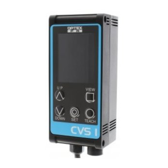
Color Area Vision Sensor
CVS1-RA Series
CVS1-□10-RA
CVS1-□20-RA
Instruction Manual
●Thank you for purchasing this product. Before using this product, confirm that the
product you have received is the product that you requested.
●Read this instruction manual thoroughly before use, and keep it in a safe location.
Indicates that incorrect use may lead to a hazard-
Warning
ous situation resulting in injury or death. Also indi-
cates a risk of significant property damage.
●This product is not explosion-proof and should not be used around flammable or explosive gases or liquids.
●Doing so may cause injury, fire, or electric shock. This product cannot be used as protective equipment
for the purpose of protecting the human body.
●It is dangerous to wire or attach/remove the connector while the power is on. Make sure to turn off the
power before operation.
●Installing in the following locations may result in malfunction:
1. Dusty or steamy locations.
2. Locations where corrosive gas is generated.
●The product is not designed for outdoor use.
●Do not wire with high voltage cables or power lines. Doing so may cause malfunction or damage by
induction.
●Detection characteristics may vary depending on the state of the target object and variations among
individual products.
●Do not use the product in water.
●Do not disassemble, repair, or modify this product. Doing so may cause injury, fire, or electric shock.
●Operate within the rated ranges.
INCLUDED ACCESSORIES
Please confirm that the following accessories are included in the box.
• CVS1-□□□-RA
• This instruction manual • Mounting screws (M4 x 50), 2 pcs.
I/O circuit diagram
7.5 kΩ
15 kΩ
Protection diode
*1: Characters in red are
*2: Because 2/3 is set for
Teach input (pink wire) timing chart
(when the specified bank is
(Start)
(Color check)
●One-point teaching
Bank select 2 /
Teaching input
>3sec.
●Two-point teaching
(Start)
(Checking at first point)
Bank select 2 /
Teaching input
>3sec.
Names of parts
LCD screen
Operating buttons
Power / input/output wire
External connector
CVS1-□21-RA
CVS1-□40-RA
0633133
W a r n i n g
C a u t i o n
3. Locations with direct exposure to water or oil
splashes.
4. Locations where heavy vibrations or impacts
may occur.
(including washers and nuts)
Brown:
12 to 24 V power
Orange/Black:
Bank select 0
Yellow/Black:
Bank select 1
Pink:
Bank select 2 (17/18) / Teaching input
(0 to
Purple:
Bank select 3 / Synchronous input (Set using
Red/Black:
Lower limit input / Bank select 3 input (18) *2
Black:
Judgment output
Blue:
0 V power
settings.
BANK
, operation is performed as "Lower limit input."
OUTSIDE
0 to
16)
(End)
3sec.
(Checking at second point / End)
<3sec.
>3sec.
Mounting holes
Used for mounting this device.
Use M4 × 50 mm screws or longer.
(φ4.3, pitch: 87 mm, depth: 4 mm)
Camera and lights (back of product)
Specifications
Model
Detection angle
Working distance
Field of view (±10%)
Light source
Power supply voltage
Current consumption
Inspection window size
Illumination life
Response time
Output signal
Input
Protection category
Operating temperature/
humidity
Storage temperature/humidity
Vibration resistance
Shock resistance
Applicable regulations
Applicable standards
Material
Weight
Dimensions
2-φ4.3
Tightening torque:
0.8 N・m or less
11.2
13.2 15.5
Options
Category
Remote monitor
Extension cable (3 m)
External bar light
*Requires power supply for light.
Power supply for light
Mounting bracket for
bar light
16)
.)
SYNCHRON
Display description
(2)
RUN
(3)
F
[
]
(4)
CH 0
(5)
Number
Name
(1)
Imaging screen The image taken by the camera is displayed according to "Screen display mode."
(2)
Mode display
(3)
Screen display
mode
(4)
Bank number
(5)
Detection color Shows the color to be detected ("darkest color," "middle color," and "brightest color" from the left).
(6)
Area lower limit • Operation screen: Shows the lower limit of the detection color area.
(7)
D e t e c t i o n
color area
(8)
A r e a u p p e r
limit
(9)
Output status ●: Output ON; ×: Output OFF
CVS1-N10-RA
CVS1-N20-RA
CVS1-P10-RA
CVS1-P20-RA
10°
20°
210 to 270 mm
90 to 150 mm
40 × 50 mm to
40 × 50 mm to
55 × 65 mm
65 × 75 mm
White LED, 12 pcs. built in
12 to 24 VDC
Max. 140 mA / 24 VDC
8×16 to 208×236
Approx. 50,000 hours
(normal temperature and humidity, brightness decreased from initial level by 1/2)
18.8 ms (initial setting), 15 ms (min.), 36.4 ms (max.)
NPN/PNP open collector output × 2
Max. 100 mA, 1.0 V residual voltage or less
Bank selection / Synchronized / External teaching input × 4
IP67
0 to +40°C/35 to 85%RH (no condensation or freezing)
-20 to +70°C/35 to 95%RH (no condensation or freezing)
10 to 55 Hz; double amplitude 1.5 mm; 2 hours in each of the X, Y, and Z directions
2
Approx. 50 G (500 m/s
), 3 times in each X, Y, and Z direction
EMC compliant (2014/30/EU); RoHS compliant (2011/65/EU)
EN 61000-6-2, EN 61000-6-4
Housing: ABS;
Emitter and receiver: Acryl
Approximately 200 g
33.8
42
29.5
21
4
28.2
95
95
87
11
External connector
Cable length: 2 m
φ5 mm, 8 cores × 0.08 mm²
Heat-resistant soft vinyl
Unit: mm
Set the sensor and the workpiece at an angle so
that there is no reflection from the built-in light.
Model
Description
CVS-M1-R
This is the monitor unit for use with the CVS series. This allows results to be
checked away from the workpiece and can be set up similar to the main unit.
CVS-C3S
This cable extends the dedicated cable or the remote monitor cable.
Up to 4 extension cables can be used (up to 15 m).
OPB-5015W-B
50 mm white light. Use if reflection from internal light is obtrusive.
OPB-10015W-B
100 mm white light. Use if reflection from internal light is obtrusive.
OPPD-15
Required when using an external light.
CVS-OPDB-2000 This bracket is for vertically mounting the OPB-5015W-B (up to 2 can be used).
CVS-OPDB-3040 This bracket is for horizontally mounting the bar light (up to 2 can be used).
Horizontal adjustment up to 30 mm and vertical adjustment up to 40 mm is possible.
CVS-OPDB-6080 This bracket is for horizontally mounting the bar light (up to 2 can be used).
Horizontal adjustment up to 60 mm and vertical adjustment up to 80 mm is possible.
(1)
(6)
5000
9999
(7)
(8)
9999
(9)
Explanation
• Operation screen: "RUN" is displayed.
• Settings screen: The settings are displayed.
Screen display mode for the imaging screen (F: Processing screen / 2: Binariza-
tion screen / D: Screen before processing)
Displays the current bank number. (0 to 15)
• Settings screen: Shows the set value for the current item.
Shows the current area of the detection color (measured value) Red: Within the
upper and lower limits, Green: Outside range
• Operation screen: Shows the upper limit of the detection color area.
• Settings screen: Shows the response time (unit: 0.1 ms)
CVS1-N21-RA
CVS1-N40-RA
CVS1-P21-RA
CVS1-P40-RA
40°
31 to 39 mm
50 to 100 mm
46 x 55 mm to
17 × 20 mm
82 x 98 mm
Emitter and receiver: PC
5° to 45°
Advertisement
Table of Contents

Subscribe to Our Youtube Channel
Related Manuals for OPTEX FA CVS1-RA Series


Summary of Contents for OPTEX FA CVS1-RA Series
- Page 1 CVS1-N10-RA CVS1-N20-RA CVS1-N21-RA CVS1-N40-RA Color Area Vision Sensor Model CVS1-P10-RA CVS1-P20-RA CVS1-P21-RA CVS1-P40-RA CVS1-RA Series Detection angle 10° 20° 40° Working distance 210 to 270 mm 90 to 150 mm 31 to 39 mm 50 to 100 mm Field of view (±10%) 40 ×...
- Page 2 This is the input time constant (noise removal time) for bank switching constant TEL: +81-(0)75-325-1314 FAX: +81-(0)75-325-2921 and external teaching. 0: 160 us / 1: 2.5 ms / 2: 5 ms / 3: 7.5 ms / 4: 10 ms (±20%) Need Tech Support? Contact Ramco 515-225-6933 http://www.optex-ramco.com OPTEX FA Homepage...
Need help?
Do you have a question about the CVS1-RA Series and is the answer not in the manual?
Questions and answers