Advertisement
Quick Links
Color Area and Shape Vision Sensor
CVS2-RA Series
CVS2-□10-RA CVS2-□20-RA CVS2-□21-RA CVS2-□40-RA
Instruction Manual
●• Thank you for purchasing this product. Before using this product, confirm that the product you have re-
ceived is the product that you requested.
●• Read this instruction manual thoroughly before use, and keep it in a safe location.
Indicates that incorrect use may lead to a hazardous
W a r n i n g
situation resulting in injury or death. Also indicates a
risk of significant property damage.
●This product is not explosion-proof and should not be used around flammable or explosive gases or liquids.
●Doing so may cause injury, fire, or electric shock. This product cannot be used as protective equipment
for the purpose of protecting the human body.
●It is dangerous to wire or attach/remove the connector while the power is on. Make sure to turn off the
power before operation.
●Installing in the following locations may result in malfunction:
1. Dusty or steamy locations.
2. Locations where corrosive gas is generated.
●The product is not designed for outdoor use.
●Do not wire with high voltage cables or power lines. Doing so may cause malfunction or damage by
induction.
●Detection characteristics may vary depending on the state of the target object and variations among
individual products.
●Do not use the product in water.
●Do not disassemble, repair, or modify this product. Doing so may cause injury, fire, or electric shock.
●Operate within the rated ranges.
Included accessories
Please confirm that the following accessories are included in the box.
• CVS2-□□□-RA
• This instruction manual • Mounting screws (M4 x 50), 2 pcs.
I/O circuit diagram
■ NPN output type
7.5 kΩ
Orange/Black:
15 kΩ
Protection diode
■ PNP output type
7.5 kΩ
Orange/Black: Bank select 0
15 kΩ
Protection diode
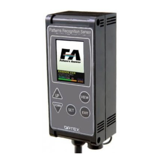
Names of parts
LCD screen
Operating buttons
Power / input/output wire
External connector
Ramco Innovations
W a r n i n g
C a u t i o n
3. Locations with direct exposure to water or oil
splashes.
4. Locations where heavy vibrations or impacts
may occur.
(including washers and nuts)
Brown:
12 to 24 V power
Bank select 0
Yellow/Black:
Bank select 1
Pink:
Bank select 2 (17/18) / Teaching input
(0 to
Purple:
Bank select 3 / Synchronous input (Set using
Red/Black:
Teaching input (16) / Bank select 3 input (17) / Auxiliary input
Black:
Judgment output
Blue: 0 V power
Blue:
0 V power
Yellow/Black: Bank select 1
Pink: Bank select 2 (17/18) / Teaching input
(0 to
Purple:
Bank select 3 / Synchronous input (Set using
Red/Black: Teaching input (16) / Bank select 3 input (17) / Auxiliary input
Black: Judgment output
Brown: 12 to 24 V power
*: Characters in red are
BANK
Mounting holes
Used for mounting this device.
Use M4 × 50 mm screws or longer.
(φ4.3, pitch: 87 mm, depth: 4 mm)
Camera and lights (back of product)
Specifications
Model
Detection angle
Working distance
Field of view (±10%)
Light source
Power supply voltage
Current consumption
Inspection window size
Illumination life
Response time
Output signal
0633143
Input
Protection category
Operating temperature/humidity
Storage temperature/humidity
Vibration resistance
Shock resistance
Applicable regulations
Applicable standards
Material
Weight
Dimensions
2-φ4.3
Tightening torque:
0.8 N・m or less
13.2 15.5
Options
Category
Remote moni-
tor
Extension cable
(3 m)
Screen description: Color identification sensor
■ Operation screen
(1)
16)
.)
SYNCHRON
{
PARAMETER
(2)
TEACH I NG
SYSTEM
(3)
THRU
{
(4)
■ Using the sort function
THRU 1
16)
.)
SYNCHRON
Number
Name
(1)
Imaging screen The image taken by the camera is displayed according to "Screen display mode."
settings.
(2)
Menu
(3)
Screen display mode Shows the current screen display mode (from THRU / COL1 / COL2 / COLR / LIVE).
(4)
Area bar graph Displays the current area in a logarithmic graph (top: color 1, bottom: color 2).
(5)
Detection color The detection color on the left becomes the darkest color and the color on the
(6)
Bank number
(7)
Output status /
Sorting number
(8)
Monitored bank
number
(9)
Response time
(10)
Communication
status
www.optex-ramco.com
CVS2-N10-RA
CVS2-N20-RA
CVS2-P10-RA
CVS2-P20-RA
10°
210 to 270 mm
90 to 150 mm
40 × 50 mm to
40 × 50 mm to
55 × 65 mm
65 × 75 mm
White LED, 12 pcs. built in
12 to 24 VDC
Max. 140 mA / 24 VDC
8×16 to 208×236
Approx. 50,000 hours (normal temperature and humidity, brightness decreased from initial level by 1/2)
18.8 ms (initial setting), 15 ms (min.), 36.4 ms (max.)
NPN/PNP open collector output × 2
Max. 100 mA, 1.0 V residual voltage or less
Bank selection / Synchronized / External teaching input × 4
0 to +40°C/35 to 85%RH (no condensation or freezing)
-20 to +70°C/35 to 95%RH (no condensation or freezing)
10 to 55 Hz; double amplitude 1.5 mm; 2 hours in each of the X, Y, and Z directions
Approx. 50 G (500 m/s2), 3 times in each X, Y, and Z direction
EMC compliant (2014/30/EU); RoHS compliant (2011/65/EU)
EN 61000-6-2, EN 61000-6-4
Housing: ABS;
Emitter and receiver: Acryl
Approximately 200 g
33.8
42
29.5
21
4
28.2
95
95
87
11
External connector
Cable length: 2 m
φ5 mm, 8 cores × 0.08 mm²
Heat-resistant soft vinyl
Unit: mm
11.2
Model
Description
CVS-M1-R This is the monitor unit for use with the CVS series. This allows results to be
checked away from the workpiece and can be set up similar to the main unit.
CVS-C3S
This cable extends the dedicated cable or the remote monitor cable.
Up to 4 extension cables can be used (up to 15 m).
■ Settings screen
{
[
]
BANK
(5)
BANKCOPY
[
]
COLOR% 1
(6)
BANK 0
THRU
100 300
(7)
1214 658
(11)
BANK 0
Color 1: Threshold
(7)
1
Color 1: Current value
(8)
Explanation
Displays the settings and edit menus.
The orange-colored area represents the area upper and lower limits.
right becomes the brightest (top: color 1, bottom: color 2).
Displays the current bank number. (0 to 14)
Orange: Output ON, Green: Output OFF
Shows the sorted bank number when the sorting function is used (bottom figure).
Allows monitoring of the color and area of banks other than the current bank
when the sorting function is used.
Represents the time between the start of imaging and when the output is issued
(unit: 0.1 ms).
Displays the communication status.
S: Normal read command reception / response complete C: Normal setting command
reception / response complete
S: Data error in read command C: Data error in setting command ?: Incorrect command
ph 800-280-6933
CVS2-N21-RA
CVS2-N40-RA
CVS2-P21-RA
CVS2-P40-RA
20°
40°
31 to 39 mm
50 to 100mm
46 x 55 to
17 × 20 mm
82 x 98 mm
IP67
Emitter and receiver: PC
5° to 45°
Set the sensor and the workpiece at an angle so
that there is no reflection from the built-in light.
16
0
3
(9)
TM 485
S
(10)
Color 2: Threshold
Color 2: Current value
Advertisement

Related Manuals for OPTEX FA CVS2-RA Series


Summary of Contents for OPTEX FA CVS2-RA Series
- Page 1 Color Area and Shape Vision Sensor CVS2-N10-RA CVS2-N20-RA CVS2-N21-RA CVS2-N40-RA Model CVS2-P10-RA CVS2-P20-RA CVS2-P21-RA CVS2-P40-RA CVS2-RA Series Detection angle 10° 20° 40° Working distance 210 to 270 mm 90 to 150 mm 31 to 39 mm 50 to 100mm Field of view (±10%) 40 ×...
- Page 2 ● Screen description: Pattern matching sensor Position correction, Scaling correction: STD TEACH Setting the position correction and scaling correction helps with workpiece position shifting. With the correction function, a color and pattern for correction are registered, and correct the color's ■...
- Page 3 ● Position correction, Scaling correction: STD TEACH Screen description: Pattern matching sensor Setting the position correction and scaling correction helps with workpiece position shifting. With the correction function, a color and pattern for correction are registered, and correct the color's ■...
- Page 4 TEL: +81-(0)75-325-1314 FAX: +81-(0)75-325-2921 setting is 16 or 17). LANGUAGE L a n g u a g e Selects the language of the menus. http://www.optex-fa.com OPTEX FA Homepage selection 0: English / 1: Japanese (kana) Ramco Innovations www.optex-ramco.com ph 800-280-6933...
Need help?
Do you have a question about the CVS2-RA Series and is the answer not in the manual?
Questions and answers