
Related Manuals for probst STAZ-SLC


Summary of Contents for probst STAZ-SLC
- Page 1 Operating Instructions Translation of original operating instructions Selective Layer Clamp STAZ-SLC 5705.0015...
- Page 2 Bitte beachten Sie, dass das Produkt ohne vorliegende Betriebsanleitung in Landessprache nicht eingesetzt / in Betrieb gesetzt werden darf. Sollten Sie mit der Lieferung des Produkts keine Betriebsanleitung in Ihrer Landessprache erhalten haben, kontaktieren Sie uns bitte. In Länder der EU / EFTA senden wir Ihnen diese kostenlos nach.
-
Page 3: Table Of Contents
Maintenance and care ............................18 Maintenance ..............................18 6.1.1 Mechanical ............................... 18 6.1.2 Hydraulic ..............................19 Trouble shooting ............................20 Repairs ................................21 Safety procedures ............................21 Hints to the type plate ..........................22 Hints to the renting/leasing of PROBST devices ..................22 5705.0015... -
Page 4: Ec-Declaration Of Conformity
Safety of machinery - safety distances to prevent hazard zones being reached by upper and lower limbs (ISO 13857:2008) Authorized person for EC-documentation: Name: J. Holderied Address: Probst GmbH; Gottlieb-Daimler-Straße 6; 71729 Erdmannhausen, Germany Signature, information to the subscriber: Erdmannhausen, 23.07.2018................ -
Page 5: Safety
Safety 4 / 22 Safety Safety symbols Danger to life! Identifies imminent hazard. If you do not avoid the hazard, death or severe injury will result. Hazardous situation! Identifies a potentially hazardous situation. If you do not avoid the situation, injury or damage to property can result. -
Page 6: Safety Marking
Safety 5 / 22 Safety Marking PROHIBITION SIGN Symbol Meaning Order-No. Size 2904.0210 Ø30 mm It is not allowed to stand under hanging loads. Danger to life! 2904.0209 Ø50 mm 2904.0204 Ø80 mm 2904.0213 Ø30 mm The transportation of non-rectangular goods is not allowed! 2904.0212 Ø50 mm 2904.0211... -
Page 7: Personal Safety Requirements
Safety 6 / 22 Personal safety requirements Each operator must have read and understood the operating instructions (and all safety instructions). Only qualified, authorized personal is allowed to operate the device and all devices which are connected (lifting device/carrier). The manual guiding is only allowed for devices with handles. Protective equipment ... -
Page 8: Hydraulic
Safety 7 / 22 2.8.2 Hydraulic Check all hydraulic hoses and connection for tightness. Only experts are allowed to replace faulty parts (depressurized) Ensure a clean working environment before opening the hydraulic connection. The hydraulic hoses must be free of breaks and abrasion. Take care that there are no outstanding edges, where the hoses could hook in. -
Page 9: Safety In Hydraulic Pressure Mode
Safety 8 / 22 2.9.2 Safety in Hydraulic pressure mode The best gripping power will be achieved if the control lever is pressed two more seconds after the gripping (closing action). Subsequent the control lever must be moved back in the neutral position. ... -
Page 10: General
General Authorized use The device STAZ-SLC is specially applicable for the use on fork lift. This device is exclusive applicable for gripping and transporting of large elements or vertically steel strapped and non-steel strapped packs of stones, which are not exceed the load capacity of the device. - Page 11 General 10 / 22 NOT ALLOWED ACTIVITIES: Unauthorized alterations of the device and the use of any self-made additional equipment could cause danger and are therefore forbidden! Never exceed the carrying capacity/working load limit (WLL) and the nominal width/gripping range of the device.
-
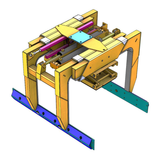
Page 12: Survey And Construction
Survey and construction Gear rack Flange plate Slide guidings Hydraulic adjustable height stop Hydraulic cylinder Rubber gripper Technical data Type Dead weight Gripping range Load capacity/WLL Inside height STAZ-SLC ~310 kg 370 - 1.370 mm 1.500 kg 500 (700) mm 5705.0015... -
Page 13: Installation
Installation 12 / 22 Installation Mechanical connection Use only original accessories, in case of doubt consult the manufacturer. Take care that the carrying capacity / working load limit (WLL) of the lifting device/carrier is not exceeded, through the load of the device, the attaching devices (turning device, fork sleeves etc.) and the additional load of the gripping goods! 4.1.1 Attachment with crane boom (optional) -
Page 14: Fork Sleeves (Optional)
Installation 13 / 22 4.1.3 Fork sleeves (optional) To establish a mechanical connection between the fork lift and the fork sleeve you have to put the fork into the fork sleeve and fix it with the locking bolt or with a chain/rope, connected to the eyelet on the fork sleeves and the lift frame. -
Page 15: Hydraulic Turning Device (Optional)
Installation 14 / 22 4.1.4 Hydraulic turning device (optional) There must be a universal joint between the hydraulic turning device and the crane boom or fork sleeves, because the device must have the possibility to swing in each position of the crane boom or fork sleeve. -
Page 16: Hydraulic Control Circuit With Uav
Installation 15 / 22 4.2.3 Hydraulic control circuit with UAV To use the device two separate hydraulic circuits (three circuits with UAV) are required. Is there only one (two) hydraulic circuit on your truck, you can split one of the circuits by using an electromagnetic valve ELMV. -
Page 17: Operation
Operation 16 / 22 Operation Device operation All the functions of the device (open, close) are controlled with the valve control lever on the fork lift truck As long as the valve control lever is activated, the functions (“open” and “close”) will take place. ... - Page 18 Operation 17 / 22 5705.0015...
-
Page 19: Maintenance And Care
Maintenance and care 18 / 22 Maintenance and care Maintenance To ensure the correct function, safety and service life of the device the following points must be executed in the maintenance interval. Used only original spare parts, otherwise the warranty expires. All operations may only be made in unpressurised, electro less and closed state of the device! For all operations you have to make sure, that the device will not close unintended. -
Page 20: Hydraulic
Maintenance and care 19 / 22 After 50 operasting hours Grease all slidings at the grease nipples with a grease gun (see arrows). 6.1.2 Hydraulic Service interval Maintenance work First inspection after Control and tighten all hydraulic thread joints and connection. 25 operating hours (The implementation is only allowed by an expert). -
Page 21: Trouble Shooting
Maintenance and care 20 / 22 Trouble shooting ERROR CAUSE REPAIR The clamping-power is not big enough, the load is slipping out (optional) The grippers are worn Replace the grippers (optional) The maximum load is exceed Reduce the weight of. the load (Adjustment of the opening width) The actual opening width is not correct Adjust the opening width according to... -
Page 22: Repairs
Maintenance and care 21 / 22 Repairs Only persons with the appropriate knowledge and ability are allowed to repair the device. Before the device is used again, it has to be checked by an expert. Safety procedures It is the contractor’s responsibility to ensure that the device is checked by an expert in periods of max. -
Page 23: Hints To The Type Plate
Example: Hints to the renting/leasing of PROBST devices With every renting/leasing of PROBST devices the original operating instructions must be included unconditionally (in deviation of the users country's language, the respective translations of the original operating instructions must be delivered additionally)! - Page 24 Greifer mit Parallel-Gleitführungen Grabs with parallel-slide bearing guides Art.-Nr.: 60200015 Probst GmbH Telefon +49 7144 3309-0 www.probst-handling.de Gottlieb-Daimler-Straße 6 +49 7144 3309-50 info@probst-handling.de 71729 Erdmannhausen, Germany...
- Page 25 After each completed performance of a maintenance interval the included form must be fill out, stamped, signed and send back to us immediately 1) via e-mail to service@probst-handling.de / via fax or post Operator: _ _ _ _ _ _ _ _ _ _ _ _ _ _ _ _ _...
- Page 26 ~ 1270 min. ÖW ~ 292 mit STB1S2 Zkl. 1250 ~ 218 max. ÖW ~ 1292 mit STB1S2 © all rights reserved conform to ISO 16016 Datum Name Benennung Kommisionierzange STAZ-SLC Erst. 13.3.2007 P.Hafenbrak Gepr. 18.2.2014 P.Hafenbrak Artikelnummer/Zeichnungsnummer Blatt D57050015 Zust.
- Page 27 47910297 46100134 siehe separate Liste see separate list 47100124 siehe separate Liste see separate list 20100018 © all rights reserved conform to ISO 16016 Datum Name Benennung Kommisionierzange STAZ-SLC Erst. 18.2.2014 P.Hafenbrak Gepr. 18.2.2014 P.Hafenbrak Artikelnummer/Zeichnungsnummer Blatt E57050015 Zust. Urspr.
- Page 28 20100004 20000007 20040022 36400009 20040005 36400058 20100004 20100004 20100004 36400055 20040036 20100004 36400055 20100004 36400058 20100004 20100004 40090046 20000007 siehe separate Liste 20040005 see separate list 20040022 36410158 20040036 20100004 36400009 20040022 46100214 20100004 20040005 20100004 20000007 36400058 20100004 36400055 20100004 36400055 20100004...
- Page 29 Artikel 21210015 + 20480012 + 2x21350008 36420020 auch vormontiert unter 40090080 bestellbar items 21210015 + 20480012 + 2x21350008 could also be ordered pre-mounted by 40090080 21350008 20100015 36420020 20480012 21350008 21210015 30330039 20000009 © all rights reserved conform to ISO 16016 Datum Name Benennung...
- Page 30 47100127 siehe separate Liste see separate list 47100126 siehe separate Liste 10100192 see separate list Länge 26 mm length 26 mm 20400003 20400003 20000020 47100125 20100016 siehe separate Liste see separate list 20000009 20400002 20000210 10700002 22200088 siehe Zeichnung 47100124 Pos.10 see drawing 47100124 Pos.10 20020005 47100147...
- Page 31 20100016 20400003 10100192 Länge 64 mm 10100192 length 64 mm 20400003 Länge 38,5 mm length 38,5 mm 20400003 20000061 20100016 20400003 20000059 © all rights reserved conform to ISO 16016 Datum Name Benennung Unterteil Erst. 26.1.2010 Dietrich.Pannier Gepr. 19.7.2018 I.Krasnikov Aufsetzvorrichtung STAZ Artikelnummer/Zeichnungsnummer Blatt...
- Page 32 20100016 16000003 siehe Zeichnung 47100125 Pos.4 see drawing 47100125 Pos.4 20400003 © all rights reserved conform to ISO 16016 20000062 Datum Name Benennung Scherenteil aussen Erst. 26.1.2010 Dietrich.Pannier Gepr. 19.7.2018 I.Krasnikov Aufsetzvorrichtung STAZ Artikelnummer/Zeichnungsnummer Blatt E47100125 Zust. Urspr. Ers. f. Ers.
- Page 33 20000060 10100192 20400003 Länge 51 mm length 51 mm 20100016 20400003 © all rights reserved conform to ISO 16016 Datum Name Benennung Oberteil Erst. 26.1.2010 Dietrich.Pannier Gepr. 19.7.2018 I.Krasnikov Aufsetzvorrichtung STAZ Artikelnummer/Zeichnungsnummer Blatt E47100127 Zust. Urspr. Ers. f. Ers. d.
- Page 34 20100016 10100165 Länge 13 mm length 13 mm 16000003 siehe Zeichnung 47100126 Pos.5 see drawing 47100126 Pos.5 © all rights reserved conform to ISO 16016 20400003 20000063 Datum Name Benennung Scherenteil innen Erst. 26.1.2010 Dietrich.Pannier Gepr. 19.7.2018 I.Krasnikov Aufsetzvorrichtung STAZ Artikelnummer/Zeichnungsnummer Blatt E47100126...
Need help?
Do you have a question about the STAZ-SLC and is the answer not in the manual?
Questions and answers