Table of Contents
Advertisement
Advertisement
Table of Contents

Related Manuals for Epever SolarV TRIRON Series


Summary of Contents for Epever SolarV TRIRON Series
- Page 2 Important Safety Instructions Please save this manual for future review. This manual contains safety, installation, and operation instructions for the Maximum Power Point Tracking (MPPT) TRIRON series controller ("the controller" as referred to in this manual). General Safety Information Read all the instructions and warnings carefully in the manual before installation. No user-serviceable components exist inside the controller.
-
Page 3: Table Of Contents
4.2 Interface Modules 4.2.1 Interface type 4.2.2 Double USB (USB1) 4.2.3 USB COM Slave (UCS) 4.2.4 Relay COM Master (RCM connects EPEVER inverter only) 28 4.2.5 Relay COM Slave (RCS connects the accessories) Copyright© 2022 SolarV GmbH All rights reserved. - Page 4 5 Parameters Setting 5.1 Battery parameters 5.1.1 Supported battery types 5.1.2 Local setting 5.1.3 Remote Setting 5.2 Load working modes 5.2.1 LCD setting 5.2.2 RS485 communication setting 6 Others 6.1 Protection 6.2 Troubleshooting 6.3 Maintenance 7 Technical Specifications Annex I Conversion Efficiency Curves Copyright©...
-
Page 5: General Information
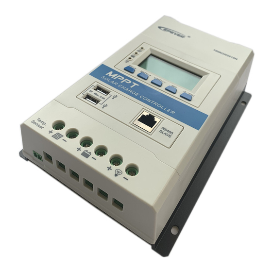
1 General Information 1.1 Overview The TRIRON series controllers are modular-designed products based on six MPPT solar controller models. The main unit (Power Module) (TRIRON****N) is a solar controller that can be integrated with different display and interface modules to meet various functional requirements. The TRIRON series controllers can automatically identify and load the drivers of various modules. -
Page 6: Characteristics
User-friendly buttons for comfortable and convenient operation Master and slave RS485 communication modules design, reading the load or inverter operating data Control the inverter switch through the relay interface Provide 5VDC power through the dual USB output interface to charge electronic devices For the BCV, FCV, LVD, and LVR, users can modify them on the local controller when the battery type is "USE."... -
Page 7: Module Types
1.3 Module Types 1-Power Modules The Power Modules control PV battery charging & load discharging without any display or interface modules installed –they can operate independently. Suppose a display or interface module is installed. In that case, it will be powered by the Power module, and the appropriate module driver will be loaded. - Page 8 LED Indicators: PV & load working status Buttons: View or set the parameters LCD PV display: voltage/current /generated energy Battery display: voltage/current/temperature Display Load: Standard 1 Display current/load working mode when the controller communicates with the PC or APP. Display voltage/current/ power consumption when the controller communicates with the inverter.
- Page 9 Interface Modules Module Function Picture RS485 interface Connect to PC or phone. USB COM View or change the controller parameters. USB interface Slave Supplies 5VDC for electronic equipment. NOTE: The USB interface is output when the load is ON. RS485 interface Connect to the inverter.
-
Page 10: Naming Rules
No COM No interface Cover The controller must be powered off for 1 minute when the user replaces the display modules or interface modules. CAUTION 1.4 Naming rules Copyright© 2022 SolarV GmbH All rights reserved. -
Page 11: Installation
2 Installation 2.1 Attentions Please read the instructions to familiarize yourself with the installation steps before installation. Be very careful when installing the batteries, especially flooded lead-acid batteries. Please wear eye protection, and have fresh water available to wash and clean any contact with battery acid. Keep the battery away from any metal objects, which may cause a short circuit of the battery. - Page 12 TRIRON1206N/2206N: 36 cell 48 cell 54 cell 60 cell System Voc 23V Voc 34V Voc 38V voltage Max. Best Max. Best Max. Best Max. Best 72 cell Voc 46V 96 cell Voc 62V System Thin-Film Module Voc 80V voltage Max. Best Max.
-
Page 13: Wire Size
72cell Voc 46V 96cell Voc 62V System Thin-Film Module Voc 80V voltage Max. Best Max. Best NOTE: The above parameter values are calculated under standard test conditions (STC (Standard Test Condition): Irradiance 1000W/m , Module Temperature 25 , Air Mass1.5.) 2.3 Wire Size The wiring and installation methods must conform to national and local electrical code requirements. -
Page 14: Mounting
Battery and Load Wire Size The battery and load wire size must conform to the rated current. The reference size is as below: Rated Rated charge Model discharge Battery wire size Load wire size current current TRIRON1206N /12AWG /12AWG TRIRON1210N TRIRON2206N /10AWG /10AWG... - Page 15 Installation Procedure: Figure2-1 Mounting Step 1: Determination of the installation location and heat-dissipation Space Figure 2-2 Schematic of wiring diagram The controller shall be installed in a place with sufficient airflow through the controller radiators and a minimum clearance of 150 mm from the upper and lower edges of the controller to ensure natural thermal convection.
- Page 16 CAUTION ensuring reliable heat dissipation through the box is important. Step 2 Connect the system in the order of battery load PV array by Figure 2-2,” Schematic Wiring Diagram” and disconnect the system in the reverse order While wiring the controller, disconnect the circuit breaker or fast-acting fuse and ensure the electrode polarity is correctly connected.
- Page 17 Step 5 Powered on the controller Connect the battery's fast-acting fuse to power the controller. Then check the battery indicator's status (the controller operates normally when the indicator is lit in green). Connect the fast-acting fuse and circuit breaker of the load and PV array. Then the system will work in preprogrammed mode.
-
Page 18: Modules Installation
3 Modules installation Copyright© 2022 SolarV GmbH All rights reserved. - Page 19 Copyright© 2022 SolarV GmbH All rights reserved.
-
Page 20: Module Introduction
4 Module Introduction Display Module 4.1.1 Display Basic1 (DB1) 1 Charging and battery LED indicator Indicator Color Status Information PV charges the battery with Green On Solid a low current 1. No sunlight Green 2. Connection Error 3. Low PV voltage Green Slowly flashing(1Hz) Normal charging... -
Page 21: Display Standard1 (Ds1)
Battery Capacity Level (BCL) Indicator Color Status Information Green 25% indicators slowly flashing 0%to <25% 50% indicators slowly flashing Green 25%to <50% 25% indicators are ON 75% indicators slowly flashing Green 50%to <75% 25%, 50% indicators are ON 100% indicators slowly flashing Green 75% to 100% 25%,50%,75% indicators are ON... - Page 22 2 Button Mode Note In manual load mode, it can turn the load On/Off of the load via the Load ON/OFF button. Press the button Clear Fault Browsing Press the button Mode Press the button and hold on 5s to enter the setting mode Press the button to set the parameters, Setting Mode...
- Page 23 Load ON Load Load OFF Load Voltage, Current, Load mode Browse interface Press the button to cycle display the following interfaces. Load parameters Combination of the DS1 and RCM modules (To connect the system with the inverter, refer to 4.2.4) Display Voltage/Current/Consumed power Combination of the DS2 and UCS modules with the LCD (connect a LED load: refer to 4.2.5)
- Page 24 Display: Current/Consumed power/Load working mode-Timer1/ Load working mode-Timer2 Setting Clear the generated energy Operating: Step 1: Long-press the button under the PV power interface until the value flashes. Step 2: Press the button to clear the generated energy. Switch the battery temperature unit Long-press the button under the battery temperature interface.
-
Page 25: Display Standard 2 (Ds2)
Load type Operating: Step1: Press the button to switch to the load type interface, and long-press the button until the load type flashes. Step2: Press the button to select the load type. Step3: Press the button to confirm. NOTE: Please refer to 5.2 for the load working modes. 4.1.3 Display Standard 2 (DS2) 1 Indicator Indicator... - Page 26 Yellow On Solid Load ON Yellow Load OFF Controller Overheating PV&BATTLED fast flashing System voltage error When a lead-acid battery is used, the controller doesn’t have low-temperature protection. When a lithium-ion battery is used, the system voltage can’t be identified automatically. 2 Button PV browsing interface Press the button...
- Page 27 Note: The display screen can be viewed clearly when the angle between the end-users horizontal sight and the display screen is within 90°. If the angle exceeds 90°, the information on the display screen cannot be viewed clearly. Icon Information Icon Information Icon...
- Page 28 Display Voltage/Current/Power/ Consumed energy/Load working mode-Timer1/ Load working mode-Timer2 4 Setting parameters 1 Battery type Operation: Step 1: On the initial interface, press the button to browse the battery parameters. Then, press the button to enter the battery parameters setting interface. Step 2: Long-press the button to enter the battery-type interface.
- Page 29 2 Battery capacity Operation: Step 1: On the initial interface, press the button to browse the battery parameters. Then, press the button to enter the battery parameters setting interface. Step 2: Long-press the button to enter the battery-type interface. Step 3: Press the button for the battery capacity interface.
- Page 30 Operation: Step 1: On the initial interface, press the button to browse the PV parameters. Then, press button to enter the PV parameters setting interface. Step 2: Long-press the button to enter the LCD cycle time interface. Step 3: Press the button or the button to set the LCD cycle time.
-
Page 31: Interface Modules
4.2 Interface Modules 4.2.1 Interface type Output Short circuit Interface Interface type voltage/current protection USB output interface Standard USB 5VDC/2.2A(Total) RS485 com. interface RJ45 5VDC/200mA Relay interface 3.81-2P 30VDC/1A RS485 communication port RJ45 Pin Definition: Definition Instruction Definition Instruction +5VDC RS485-A 5V/200mA RS485-A... -
Page 32: Relay Com Master (Rcm Connects Epever Inverter Only)
4.2.4 Relay COM Master (RCM connects EPEVER inverter only) Note: RCM can only be connected with the EPEVER inverters, not with optional accessories. RS485 interface: When the master is set in RS485 communication mode, i.e., with a combination of the RCM and DS1/DS2 modules, the information of the inverter (to be supplied by our company) can be displayed by the DS1/DS2 module. -
Page 33: Relay Com Slave (Rcs Connects The Accessories)
4.2.5 Relay COM Slave (RCS connects the accessories) RS485 interface: When the slave is set in RS485 communication mode, i.e., with a combination of the RCS and DS1/DS2 modules, the controller's information can be displayed by the DS1/DS2 module. Relay interface: It shall connect the controller’s relay in parallel with the inverter start switch, so it can turn ON/OFF the inverter by operating the button. Copyright©... -
Page 34: Parameters Setting
5 Parameters Setting 5.1 Battery parameters 5.1.1 Supported battery types Sealed(default) Battery Flooded Lithium LiFePO4(4S/ 8S) battery Li(NiCoMn)O2 (3S/6S/7S) User 5.1.2 Local setting When the default battery type is selected, the battery voltage parameters cannot be modified. To change these parameters, select the "USE"... - Page 35 select the battery type as F04. And then, press the button to enter the battery-type interface. button to confirm and go back to the battery voltage interface automatically. 2) Press the button to select the battery type, such as select the battery type as F04. And then 3) Long-press the button to enter the battery-type interface again on the battery voltage interface.
- Page 36 the parameter. 4) Press the button to confirm and enter the next parameter. 4) Press the button to confirm and enter the next parameter. Boost charging 9—17 14.4V 5) Press the button again to display the voltage (BCV) current voltage value. Float charging 5) Press the button again to display the...
- Page 37 Battery type Sealed/Gel/Flooded LiFePO4 User Li(NiCoMn)O2 User Battery parameters User Over voltage disconnect voltage BCV+1.4V*voltage level BCV+0.3V*voltage level BCV+0.3V*voltage level Charging limit voltage BCV+0.6V*voltage level BCV+0.1V*voltage level BCV+0.1V*voltage level Over voltage reconnect voltage BCV+0.6V*voltage level BCV+0.1V*voltage level Boost charging voltage Equalize charging voltage BCV+0.2V*voltage level Boost charging voltage...
-
Page 38: Remote Setting
5.1.3 Remote Setting Setting the battery parameters by PC software Connect the controller's RJ45 port to the PC's USB port via a USB to RS485 cable. When selecting the battery type as "USE," set the voltage parameters by the PC software. Setting the battery parameters by APP Via an external WiFi module Connect the controller to an external WIFI module through a standard network cable. - Page 39 Connect the controller to the remote meter (MT50) through a standard network cable. After selecting the battery type as "USE," set the voltage parameters by the MT50. Refer to the MT50 manual or aftersales engineer for details. Controller parameters Battery voltage parameters Measure the parameters in the condition of 12V/25ºC.
- Page 40 When the battery type is "USE," the battery voltage parameters follow the following logic: Over Voltage Disconnect Over Voltage Disconnect Voltage > Over Voltage Reconnect Voltage Low Voltage Reconnect Voltage > Low Voltage Voltage. Limit Voltage; Boost Reconnect Charging voltage >Low Voltage Reconnect Voltage. Lithium Battery voltage parameters LNCM Battery type...
-
Page 41: Load Working Modes
parameters should be x2 for LFP8S. When the battery type is "USE," the Lithium battery voltage parameters follow the following logic: Over Voltage Disconnect Voltage>Over Charging Protection Voltage(Protection Circuit Modules(BMS))+0.2V; Over Voltage Disconnect Voltage>Over Voltage Reconnect Voltage Equalize Charging Voltage Reconnect Charging Voltage;... - Page 42 Operation: Step1: On the initial interface, press the button to browse the load parameters. Then, press the button to enter the load parameters setting interface. Step 2: Long-press the button to enter the load type interface. Step 3: Press the button to change the load type.
-
Page 43: Rs485 Communication Setting
5.2.2 RS485 communication setting 1) Load working mode Manual Control (default) Control ON/OFF of the load via the button or remote commands (e.g., APP or PC software). Light ON/OFF Light ON+ Timer Time Control Control the load ON/OFF time by setting the real-time clock. 2) Load mode settings Set the load modes by PC software, APP, or remote meter (MT50). -
Page 44: Others
6 Others 6.1 Protection When the charging current or power of the PV array exceeds its rated current or power, it will be charged at the rated current or power. PV Over Current WARNING: When the PV’s charging current exceeds the rated current, the PV’s open-circuit voltage cannot exceed the "maximum PV open-circuit voltage."... -
Page 45: Troubleshooting
temperature exceeds 65 °C and begins working when its temperature is below 55 °C. When the temperature detected by the optional temperature sensor is lower than the Low Temperature Protection Threshold Lithium Battery Low (LTPT), the controller will stop charging and discharging automatically. When the detected temperature is higher than the LTPT, Temperature the controller will work automatically (The LTPT is 0 °C by default and can be set within 10 ~ -40 °C). - Page 46 DB1 Charging indicator Green fast flashing Battery level shows full, battery frame and fault Check if the battery voltage is higher than OVD (over icon blink. Battery over voltage voltage disconnect voltage), and disconnect the PV. DS2 Charging indicator Green fast flashing Battery level shows full, battery frame and fault icon blink.
- Page 47 When the controller heat sink exceeds 85 , the controller will automatically cut the input and output Controller Overheating circuit. When the temperature is below 75 , the PV/BATT(orange)/Battery capacity lever(four) indicator controller will resume work. fast flashing Check whether the battery voltage matches the controller's working voltage.
-
Page 48: Maintenance
6.3 Maintenance The following inspections and maintenance tasks are recommended at least twice yearly for best performance. Make sure the controller is firmly installed in a clean and dry ambient. Make sure no block on airflow around the controller. Clear up any dirt and fragments on the radiator. -
Page 49: Technical Specifications
7 Technical Specifications Electrical Parameters TRIRON TRIRON TRIRON TRIRON TRIRON TRIRON TRIRON Item TRIRON 4215N 1206N 2206N 1210N 2210N 3210N 4210N 3215N 12/24VDC Auto Rated battery voltage Rated charge current Rated discharge current 8 32V Battery voltage range 100V 150V 138V Max. - Page 50 When a lithium battery is used, the temperature compensation coefficient will be 0 and can’t be changed. Environmental Parameters Environment temperature -25 ~+55 (LCD), -30 ~+55 (No LCD) -25 ~+50 (LCD), -30 ~+50 (No LCD) -20 ~+70 Storage temperature range Relative humidity Enclosure IP30...
-
Page 51: Annex I Conversion Efficiency Curves
Annex I Conversion Efficiency Curves Illumination Intensity: 1000W/m Temperature: 25ºC Model: TRIRON1206N Solar Module MPP Voltage(17V, 34V) / Nominal System Voltage(12V) Solar Module MPP Voltage(34V) / Nominal System Voltage(24V) Copyright© 2022 SolarV GmbH All rights reserved. - Page 52 Model: TRIRON1210N Solar Module MPP Voltage(17V, 34V) / Nominal System Voltage(12V) Solar Module MPP Voltage(34V) / Nominal System Voltage(24V) Copyright© 2022 SolarV GmbH All rights reserved.
- Page 53 Model: TRIRON2206N Solar Module MPP Voltage (17V, 34V) / Nominal System Voltage(12V) Solar Module MPP Voltage (34V) / Nominal System Voltage(24V) Copyright© 2022 SolarV GmbH All rights reserved.
- Page 54 Model: TRIRON2210N Solar Module MPP Voltage (17V, 34V,51V) / Nominal System Voltage(12V) Solar Module MPP Voltage (34V,51V,68V) / Nominal System Voltage(24V) Copyright© 2022 SolarV GmbH All rights reserved.
- Page 55 Model: TRIRON3210N Solar Module MPP Voltage (17V, 34V,51V) / Nominal System Voltage(12V) Solar Module MPP Voltage (34V,51V,68V) / Nominal System Voltage(24V) Copyright© 2022 SolarV GmbH All rights reserved.
- Page 56 Model: TRIRON3215N Solar Module MPP Voltage (17V, 34V,68V) / Nominal System Voltage(12V) Solar Module MPP Voltage (34V,68V,102V) / Nominal System Voltage(24V) Copyright© 2022 SolarV GmbH All rights reserved.
- Page 57 Model: TRIRON4210N Solar Module MPP Voltage (17V, 34V,51V) / Nominal System Voltage(12V) Solar Module MPP Voltage (34V,51V,68V) / Nominal System Voltage(24V) Copyright© 2022 SolarV GmbH All rights reserved.
- Page 58 Model: TRIRON4215N Solar Module MPP Voltage (17V, 34V,68V) / Nominal System Voltage(12V) Solar Module MPP Voltage (34V,68V,102V) / Nominal System Voltage(24V) Any changes without prior notice! Version number: 2.5 Copyright© 2022 SolarV GmbH All rights reserved.
Need help?
Do you have a question about the SolarV TRIRON Series and is the answer not in the manual?
Questions and answers