
Related Manuals for Epever SolarV AN Series


Summary of Contents for Epever SolarV AN Series
- Page 1 USER MANUAL TRACER AN SERIES - MPPT SOLAR CHARGER CONTROLLER Model: 1210AN 2210AN 3210AN 4210AN www.solarv.de Copyright © 2020 SolarV GmbH All rights reserved...
-
Page 2: Table Of Contents
CONTENTS 1. General Information............................ 1 Overview............................1 Characteristics..........................2 Naming Rules of Controller models....................2 Maximum Power Point Tracking Technology...................3 Battery Charging Stage........................4 2. Installation Instructions..........................7 General Installation Notes........................7 PV Array Requirements........................7 Wire Size............................10 Mounting............................11 3. Operation..............................14 Button............................. - Page 3 Important Safety Instructions Please keep this manual for future review. This manual contains all instructions of safety, installation and operation for Tracer AN series Maximum Power Point Tracking (MPPT) controller ("the controller" as referred to in this manual). General Safety Information Read carefully all the instructions and warnings in the manual before installation.
-
Page 4: General Information
1. General Information 1.1 Overview Tracer AN series controller is based on common negative design and advanced MPPT control algorithm, with LCD displaying running status, this product is artistic, economical and practical. The MPPT control algorithm can minimize the maximum power point loss rate and loss time, quickly track the maximum power point of the PV array and obtain the maximum energy from solar modules under any conditions;... -
Page 5: Characteristics
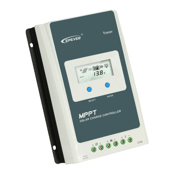
1.2 Characteristics Figure 1 Product Characteristics ❶ ❻ SELECT button RS485 communication port ❷ ❼ ★ Mounting Hole Φ5mm port ❸ ❽ PV Terminals ENTER button ❹ ❾ Battery Terminals ❺ Load Terminals ★If the temperature sensor is short-circuited or damaged, the controller will charge or discharge at the default temperature setting of 25 ºC. -
Page 6: Maximum Power Point Tracking Technology
1.4Maximum Power Point Tracking Technology Due to the nonlinear characteristics of solar array, there is a maximum energy output point (Max Power Point) on its curve. Traditional controllers, with switch charging technology and PWM charging technology, can’t charge the battery at the maximum power point, so can’t harvest the maximum energy available from PV array, but the solar charge controller with Maximum Power Point Tracking (MPPT) Technology can lock on the point to harvest the maximum energy and deliver it to the battery. -
Page 7: Battery Charging Stage
In actual application, as shading from cloud, tree and snow, the panel maybe appear Multi-MPP, but in actually there is only one real Maximum Power Point. As the below Figure 1-3 shows: Figure 1-3 Mutil-MPP Curve If the program works improperly after appearing Multi-MPP, the system will not work on the real max power point, which may waste most solar energy resources and seriously affect the normal operation of the system. - Page 8 A) Bulk Charging In this stage, the battery voltage has not yet reached constant voltage (Equalize or Boost Voltage), the controller operates in constant current mode, delivering its maximum current to the batteries (MPPT Charging). B) Constant Charging When the battery voltage reaches the constant voltage setpoint, the controller will start to operate in constant charging mode, this process is no longer MPPT charging, and in the meantime the charging current will drop gradually, the process is not the MPPT charging.
- Page 9 calculate the time of constant voltage working. When the accumulated time reach to 3 hours, the charging mode will turn to Float Charging. 2) If the controller time is not adjusted, the controller will equalize charge battery once every month following the inner time. C) Float Charging After the Constant voltage stage, the controller will reduce charging current to Float Voltage setpoint.
-
Page 10: Installation Instructions
Installation Instructions 2.1 General Installation Notes Please read the entire installation instructions to get familiar with the installation steps before installation. Be very careful when installing the batteries, especially flooded lead-acid battery. Please wear eye protection, and have fresh water available to wash and clean any contact with battery acid. ... - Page 11 Tracer1210/2210/3210/4210AN: 36 cell 48 cell 54 cell 60 cell System Voc<23V Voc<31V Voc<34V Voc<38V voltage Max. Best Max. Best Max. Best Max. Best Thin-Film 72 cell Voc<46V 96 cell Voc<62V System Module Voc voltage Max. Best Max. Best >80V NOTE: The above parameter values are calculated under standard test conditions STC (Standard Test Condition):Irradiance 1000W/m 2 ,Module Temperature 25℃,...
- Page 12 WARNING: When the power of PV module is greater than the rated charging power, and the maximum open-circuit voltage of PV array is more than 60(Tracer**06AN)/100V(Tracer**10AN)(at the lowest environmental temperature), the controller may be damaged. According to “Peak Sun Hours diagram”, if the power of PV array exceeds the rated charging power of controller, then the charging time as per the rated power will be prolonged, so that more energy can be obtained for charging the battery.
-
Page 13: Wire Size
2.3 Wire Size The wiring and installation methods must conform to all national and local electrical code requirements. 2.3.1 PV Wire Size Since PV array output can vary due to the PV module size, connection method or sunlight angle, the minimum wire size can be calculated by the Isc of PV array. -
Page 14: Mounting
CAUTION: The wire size is only for reference. If there is a long distance between the PV array and the controller or between the controller and the battery, larger wires can be used to reduce the voltage drop and improve performance. CAUTION: For the battery, the recommended wire will be selected according to the conditions that its terminals are not connected to any additional inverter. - Page 15 CAUTION: If the controller is to be installed in an enclosed box, it is important to ensure reliable heat dissipation through the box. Figure 2-2 Schematic of wiring diagram Step 2 : Connect the system in the order of ❶battery ❷...
- Page 16 of PV array, battery and load can also be ungrounded, but the grounding terminal on its shell must be grounded, which may effectively shield the electromagnetic interference from the outside, and prevent some electric shock to human body due to the electrification of the shell. CAUTION: For common-negative system, such as motorhome, it is recommended to use a common-negative controller;...
-
Page 17: Operation
3. Operation 3.1 Button Mode Note In load manual mode, it can turn the load On/Off via the Load ON/OFF “ENTER” button. Clear Fault Press the “ENTER” button. Press the “SELECT” button. Browsing Mode Press the “ENTER” button. and hold on 5s to enter the setting mode Press the “SELECT”... - Page 18 Night No charging Charging PV Voltage, Current, Power Battery capacity, In Charging Battery Battery Voltage, Current, Temperature Battery Type Load ON Load Load OFF Current/Consumed energy/Load mode Fault Indication Status Icon Description Battery over Battery level shows empty, battery frame blink, fault icon blink discharged Battery over Battery level shows full, battery frame blink, fault icon blink...
-
Page 19: Setting
3) Browse interface 3.3 Setting Clear the generated energy Operation: Step 1: Press the “ENTER” button and hold 5s under the PV generated energy interface and the value will be flashing. Step 2: Press the “ENTER” button to clear the generated energy.. Switch the battery temperature unit Press the “ENTER”... - Page 20 Item Lead-acid battery Lithium battery Sealed(default) LiFePO4(4s/12V; 8s/24V) Li(NiCoMn)O (3s/12V; 6s/24V) Flooded User(9~34V) User(9~17V/12V; 18~34V/24V) CAUTION: When the default battery type is selected, the battery voltage control parameters will be set by default and can’t be changed. To change these parameters, select "User" battery type.
- Page 21 (1) PC setting Connection (2) APP software setting Download the PC and APP software: http://www.epever.com—Support— Software(Select the software according to the description ) (3) Setting the control voltage value The following rules must be observed when modifying the parameter values in User for lead-acid battery.
- Page 22 Voltage>Boost Reconnect Charging Voltage; Ⅲ. Low Voltage Reconnect Voltage > Low Voltage Disconnect Voltage ≥ Discharging Limit Voltage; Ⅳ. Under Voltage Warning Reconnect Voltage > Under Voltage Warning Voltage ≥ Discharging Limit Voltage; Ⅴ. Boost Reconnect Charging voltage > Low Voltage Reconnect Voltage; Ⅵ.
- Page 23 ②Load working mode settings (1) PC setting (2) APP software setting Download the PC and APP software: http://www.epever.com—Support—Software(Select the software according to the description ) (3) MT50 Setting CAUTION: For detailed setting methods, please refer to the instructions or contact after-salessupport.
-
Page 24: Accessories (Optional)
3.4 Accessories (optional) Acquisition of battery temperature for undertaking temperature compensation of controlparameters, the standard length of the Remote cable is 3m (length can be customized). The RTS300R47K3.81A Temperature Sensor connects to the port (4 th ) on the controller. (RTS300R47K3.81A) NOTE: The temperature sensor short-circuited or damaged, the controller will be charging ordischarging at the default... -
Page 25: Protections, Troubleshooting And Maintenance
4. Protections, Troubleshooting and Maintenance 4.1.Protection When the charging current or power of the PV array exceeds the controller’s rated PV Over current or power, it will be charged at the rated current orpower. Current/power NOTE: When the PV modules are in series, ensure that the open-circuit voltage of the PV array does not exceed the "maximum PV open-circuit voltage"... -
Page 26: Troubleshooting
★When the internal temperature is 81℃, the reducing power charging mode which reduce the charging power of 5%,10%,20%,40% every increase 1 ℃is turned on. If the internal temperature is greater than 85℃, the controller will stop charging. When the temperature declines to be below 75 ºC, the controller will resume. -
Page 27: Maintenance
4.3 Maintenance The following inspections and maintenance tasks are recommended at least two times per year for best performance. Make sure controller firmly installed in a clean and dry ambient. Make sure no block on air-flow around the controller. Clear up any dirt and fragments on radiator. -
Page 28: Technical Specifications
Technical Specifications Electrical Parameters ①When a lithium battery is used, the system voltage can’t be identified automatically. ②At minimum operating environment temperature ③At 25℃ environment temperature ④When a lithium battery is used, the temperature compensate coefficient will be 0,and can’t bechanged. Environmental Parameters -25℃~+45℃(100% input and output) ◆... - Page 29 Mechanical Parameters Tracer1210AN Tracer2210AN Tracer3210AN Tracer4210AN Item Dimension 172x139 x 44mm 220x154x 52mm 228x164x55mm 252x180x63mm Mounting 124x130 mm 170x145mm 170x155 mm 204x171 mm dimension Mounting hole Φ5mm size 12AWG(4mm 2 ) 6AWG(16mm 2 ) 6AWG(16mm 2 ) 6AWG(16mm 2 ) Terminal Recommended 12AWG(4mm 2 )
-
Page 30: Annex I Conversion Efficiency Curves
6 Annex I Conversion Efficiency Curves llumination Intensity: 1000W/m 2 Temp: 25ºC Model: Tracer1210AN Solar Module MPP Voltage(17V, 34V) / Nominal System Voltage(12V) Solar Module MPP Voltage(34V,51V,68V) / Nominal System Voltage(24V) www.solarv.de Copyright © 2021 SolarV GmbH All rights reserved... - Page 31 Model: Tracer2210AN Solar Module MPP Voltage(17V, 34V) / Nominal System Voltage(12V) Solar Module MPP Voltage(34V,51V,68V) / Nominal System Voltage(24V) www.solarv.de Copyright © 2021 SolarV GmbH All rights reserved...
- Page 32 Model: Tracer3210AN Solar Module MPP Voltage(17V, 34V) / Nominal System Voltage(12V) Solar Module MPP Voltage(34V,51V,68V) / Nominal System Voltage(24V) www.solarv.de Copyright © 2021 SolarV GmbH All rights reserved...
- Page 33 Model: Tracer4210AN Solar Module MPP Voltage(17V, 34V) / Nominal System Voltage(12V) Solar Module MPP Voltage(34V,51V,68V) / Nominal System Voltage(24V) www.solarv.de Copyright © 2021 SolarV GmbH All rights reserved...
-
Page 34: Annex Ii Mechanical Dimension Diagram
7.Annex II Mechanical Dimension Diagram Tracer1210AN (Unit: mm) www.solarv.de Copyright © 2021 SolarV GmbH All rights reserved... - Page 35 Tracer2210AN (Unit: mm) www.solarv.de Copyright © 2021 SolarV GmbH All rights reserved...
- Page 36 Tracer3210AN (Unit: mm) www.solarv.de Copyright © 2021 SolarV GmbH All rights reserved...
- Page 37 Tracer4210AN (Unit: mm) Any changes without prior notice! Version number: 2.1 www.solarv.de Copyright © 2021 SolarV GmbH All rights reserved...
- Page 38 www.solarv.de Copyright © 2021 SolarV GmbH All rights reserved www.solarv.de...
Need help?
Do you have a question about the SolarV AN Series and is the answer not in the manual?
Questions and answers