
Related Manuals for Epever Tracer-AN Series


Summary of Contents for Epever Tracer-AN Series
- Page 1 MPPT Solar controller User Manual Model: Tracer6210AN Tracer5415AN/Tracer6415AN Tracer8415AN/Tracer10415AN Tracer5420AN/Tracer6420AN Tracer8420AN/Tracer10420AN...
-
Page 3: Table Of Contents
Contents Important Safety Instructions ..............1 1 General Information................3 1.1 Overview ......................3 1.2 Characteristics ....................5 1.3 Naming rules ....................6 1.4 Included accessories ..................7 1.5 Optional accessories ..................7 2 Installation ..................10 2.1 Attentions ...................... 10 2.2 Requirements for the PV array .............. -
Page 5: Important Safety Instructions
Important Safety Instructions Please reserve this manual for future review. This manual contains all safety, installation, and operation instructions for the Tracer-AN series MPPT solar controller ("controller" referred to in this manual). Read all the instructions and warnings carefully in the manual before installation. ... - Page 6 All of the safety and operating instructions should be read, adhered to, and followed before operating the device. The entire system should be installed by professional and technical personnel.
-
Page 7: General Information
The automatic power reduction function fully ensures access to excess PV modules and high temperature running. The Tracer-AN series controller owns a self-adaptive three-stage charging mode based on a digital control circuit. This function can effectively prolong the battery's lifespan and significantly improve the system's performance. - Page 8 Programmable temperature compensation feature for batteries. Real-time energy statistics function High temperature charging automatic power reduction function 100% charging and discharging in the working environment temperature range Up to 6 controllers connection in parallel to expand the system ...
-
Page 9: Characteristics
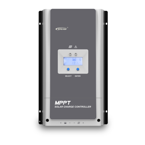
1.2 Characteristics Figure 1 Product Characteristics ❿ (Utility/Generator) dry contact ON ❶ Charging indicator interface ❷ SELECT button ⓫ RBVS interface ❸ External fuse ⓬ (Load) dry contact interface ⓭ (Utility/Generator) dry contact OFF ❹ Grounding terminal interface ❺ Screw hole(M4) ⓮... -
Page 10: Naming Rules
(1) Set the (Generator/Load) dry contact enable switch to ON, the (Load) dry contact is enabled; while it is disabled when the switch is set to OFF. (2) Connect an RTS (Remote Temperature Sensor) to remotely detect the battery temperature. The sampling distance is no longer than 20m. Suppose the temperature sensor is a short circuit or damaged. -
Page 11: Included Accessories
1.4 Included accessories Included Model Number Picture accessories Local temperature RT-MF58R47K3.81A(2P-3.81mm) 1 pcs sensor Battery voltage 2P-3.81mm 1 pcs sensor terminal (Load) dry contact 2P-3.81mm 1 pcs terminal (Utility/Generator) dry 2P-3.5mm 2 pcs contact terminal The above-included accessories are installed on the related port. Please open the controller case before checking. - Page 12 length is 1.5 m (length can be customized). Real-time monitoring the controller software updating through the Solar Station Monitor software. MT50 can display various operating data and faults of the system. The information can be displayed on a Remote meter backlight LCD screen.
- Page 13 power adjustment and communication management. For details, please refer to the user manual of the parallel adapter. CAUTION: ① For setting and operation of accessory, please refer to accessory's user manual. ② When connecting the controller to the above accessories, only one of the communication ports can be used.
-
Page 14: Installation
2 Installation 2.1 Attentions Be very careful when installing the batteries. Please wear eye protection when installing the open-type lead-acid battery and rinse with clean water in time for battery acid contact. Keep the battery away from any metal objects, which may cause a battery short circuit. ... - Page 15 72cell Voc< 46V 96cell Voc< 62V Thin-Film System voltage module Max. Best Max. Best Voc> 80V NOTE: The above parameters are calculated under standard test conditions (STC (Standard Test Condition):Module Temperature 25℃, Air Mass1.5, Irradiance 1000W/m Tracer5415/6415/8415/10415AN: 36cell 48cell 54cell 60cell Voc<...
- Page 16 NOTE: The above parameters are calculated under standard test conditions (STC (Standard Test Condition):Module Temperature 25℃, Air Mass1.5, Irradiance 1000W/m (2) Max. PV Array Power This MPPT controller has the function of charging current/power-limiting. During the charging process, when the actual charging current or charging power exceeds the rated charging current or charging power, the controller automatically limits the current or power.
- Page 17 much. In that case, it may cause the PV array's waste and increase the PV array's open-circuit voltage due to the environmental temperature. It may increase the damage probability to the controller. For the recommended maximum power of the PV array, please refer to the table below: Rated Max.
-
Page 18: Wire Size
180V(25℃) 3000W/36V 4500W/36V 4000W/48V 6000W/48V 1250W/12V 1875W/12V 2500W/24V 3750W/24V Tracer10420AN 100A 3750W/36V 5625W/36V 5000W/48V 7500W/48V 2.3 Wire size The wiring and installation methods must conform to the national and local electrical code requirements. PV wire size The PV array's output current varies with its size, connection method, and sunlight angle. The minimum wire size can be calculated by its ISC(short circuit current). -
Page 19: Dry Contact Instruction
Rated charging Model Battery wire size current Tracer5415AN 16mm /6AWG Tracer5420AN Tracer6210AN Tracer6415AN 16mm /6AWG Tracer6420AN Tracer8415AN 25mm /4AWG Tracer8420AN Tracer10415AN 100A 35mm /2AWG Tracer10420AN The wire size is only for reference. Suppose a long-distance exists between the PV array and the controller or between the controller and the battery. In that case, larger wires shall be used to reduce the voltage drop and improve the system performance. - Page 20 2) Control the load first disconnection and second disconnection. Battery Voltage (V Under Voltage Warning Voltage (V Under Voltage Warning Recover Voltage (V UVWR Low Voltage Disconnect Voltage(V Low Voltage Reconnect Voltage(V (Utility/Generator) dry contact OFF interface ≤V : The (Utility/Generator) dry contact OFF interface controls the load ❶ first disconnection.
-
Page 21: Mounting
Tracer-AN series controllers have no battery reverse protection. Do not reverse the battery during the wiring. Otherwise, the controller may be damaged. - Page 22 Step 3: Connect the battery (Left) and PV (Right) NOTE: Disconnect the system in the reverse order. Tracer-AN series controllers have no battery reverse protection. Do not reverse the battery during the wiring. Otherwise, the controller may be damaged. ...
- Page 23 Single controller Connection in parallel Step 4:Grounding Tracer-AN series are common-negative controllers. Negative terminals of the PV array, the battery can be grounded simultaneously, or any terminal is grounded. However, according...
- Page 24 to the practical application, the PV array's negative terminals, battery, and load can also be ungrounded. Simultaneously, the grounding terminal on the shell must be grounded, which effectively shields the electromagnetic interference from the outside and prevents some electric shock to the human body due to the electrification of the shell. For common-negative systems, such as the RV system, it is recommended to use a common-negative controller.
-
Page 25: Operation
3 Operation 3.1 Indicator Indicator Color Status Instruction PV connection is normal, but the Green ON solid voltage is low and not charging. No PV voltage(night time) or PV Green connection fault Green Slowly flashing PV is charging Green Fast flashing PV over voltage Note: The fault indicator refers to chapter 3.3, "LCD... -
Page 26: Lcd Display
3.3 LCD Display 1) Status Description Name Symbol Status Night No charge PV array Charging PV array's voltage, current, and generate energy Battery capacity, In Charging Battery Battery Voltage, Current, Temperature Battery type (Load) dry contact connected Load (Load) dry contact disconnected 2)... -
Page 27: Setting
3) Error codes Faults Charging Status Symbol Instruction Indicator indicator Battery level shows empty, Battery over Red ON battery frame blink, fault discharged solid icon blink. Battery level shows full, Battery over Slow battery frame blink, fault voltage flashing icon blink. Battery level shows current Battery over slowly... - Page 28 PC software or APP. ③ Setting the battery type via the PC software or APP software PC software Step 1: Connection Step 2: Download software www.epever.com——(Charge Controller—Windows) APP software Step 1: Connection...
- Page 29 Step 2: Download software www.epever.com——(Charge Controller (Lithium)—Android) The controller can only set the lead-acid battery type. The lithium battery type needs to be set through the PC software or APP. ④ Battery voltage control parameters Lead-acid battery parameters The parameters are measured in the condition of 12V/25 º C. Please double the values in the 24V system and quadruple the values in the 48V system.
- Page 30 Under voltage warning 12.0V 12.0V 12.0V 9~17V voltage Low voltage disconnect 11.1V 11.1V 11.1V 9~17V voltage Discharging limit 10.6V 10.6V 10.6V 9~17V voltage 0~180 Equalize Duration minutes minutes minutes 10~180 Boost Duration minutes minutes minutes minutes ⑴ To change these parameters, select "User" battery type. ⑵...
- Page 31 Low voltage disconnect voltage 11.1V 9.3V 9~17V Discharging limit voltage 10.6V 9.3V 9~17V The following rules must be observed when modifying the parameter values in User for a lithium battery. A. Over Voltage Disconnect Voltage>Over Charging Protection Voltage(Protection Circuit Modules(BMS))+0.2V; B.
-
Page 32: Others
4 Others 4.1 Protections Tracer AN series controllers have no battery reverse protection. Do not reverse the battery during the wiring. Otherwise, the controller may be damaged. Protections Instruction When the PV array's actual charging current or power exceeds current/power-limiting the controller's rated charging current or power, the controller protection charges the battery as per the rated current or power. - Page 33 When the temperature detected by the optional temperature sensor is lower than the Low Temperature Protection Lithium battery low Threshold(LTPT), the controller stops charging and discharging temperature automatically. When the detected temperature is higher than the protection LTPT, the controller resumes work automatically. (The LTPT is 0 °...
-
Page 34: Troubleshooting
4.2 Troubleshooting Faults Faults Solutions Charging LED is OFF during Confirm whether the connection PV array daytime when sunshine falls on of the PV array is correct and open-circuit PV array properly tight The battery Please check the voltage of the The wire connection is correct;... - Page 35 Clear up dirt, nesting insects, and corrosion in time. Check and confirm that the lightning arrester is in good condition. Replace a new one in time to avoid damaging the controller and even other equipment. Risk of electric shock! Ensure that all the power is turned off before the above operations, and then follow the corresponding inspections and operations.
-
Page 36: Specifications
5 Specifications Model Tracer5415AN Tracer5420N Electrical Parameters System rated voltage 12/24/36/48VDC or Auto Controller working 8V~68V voltage range Lead-acid battery type Sealed(Default)/Gel/Flooded/User Lithium battery type LiFePO4/ Li(NiCoMn)O2/ User Battery fuse 80A/ 58V Rated charging current Rated charging power 625W/12V, 1250W/24V, 1875W/36V, 2500W/48V 150V(at the lowest 200V(at the lowest Max. - Page 37 Recommended cable 6AWG/ 16mm Net Weight 3.5kg ① When connecting the controller to external devices, only one of the communication ports is used; when connecting multiple controllers in parallel, RS485 ports are for cascaded use. Model Tracer6210AN Electrical Parameters System rated voltage 12/24/36/48VDC or Auto Controller working 8V~32V...
- Page 38 Wire size 2AWG/ 35mm Recommended cable 6AWG/ 16mm Net Weight 3.5kg ① When connecting the controller to external devices, only one of the communication ports is used; when connecting multiple controllers in parallel, RS485 ports are for cascaded use. Model Tracer6415AN Tracer6420N Electrical Parameters...
- Page 39 Mounting dimension 260×224mm Φ7 Mounting hole size Wire size 2AWG/ 35mm Recommended cable 6AWG/ 16mm Net Weight 4.5kg ① When connecting the controller to external devices, only one of the communication ports is used; when connecting multiple controllers in parallel, RS485 ports are for cascaded use. Model Tracer8415AN Tracer8420N...
- Page 40 Mechanical parameters Dimension 394×240×134mm Mounting dimension 300×228mm Φ7 Mounting hole size Wire size 2AWG/ 35mm Recommended cable 4AWG/ 25mm Net Weight 6.1kg ① When connecting the controller to external devices, only one of the communication ports is used; when connecting multiple controllers in parallel, RS485 ports are for cascaded use. Model Tracer10415AN Tracer10420N...
- Page 41 Default: 60S, Range:0~999S (0S: the backlight is ON all the LCD backlight time time) Mechanical parameters Dimension 394×242×143mm Mounting dimension 300×230mm Φ7 Mounting hole size Wire size 2AWG/ 35mm Recommended cable 2AWG/ 35mm Net Weight 7.4kg ① When connecting the controller to external devices, only one of the communication ports is used;...
-
Page 42: Appendix 1 Dimensions
Appendix 1 Dimensions (Unit: mm) Tracer5415/5420AN... - Page 43 Tracer6210AN...
- Page 44 Tracer6415/6420AN...
- Page 45 Tracer8415/8420AN...
- Page 46 Tracer10415/10420AN Any changes without prior notice! Version number: V3.1...
- Page 48 HUIZHOU EPEVER TECHNOLOGY CO., LTD. Beijing Tel: 010-82894896/82894112 Huizhou Tel: 0752-3889706 E-mail: webmaster@epsolarpv.com Website: www.epsolarpv.com.cn www.epever.com...
Need help?
Do you have a question about the Tracer-AN Series and is the answer not in the manual?
Questions and answers