
Related Manuals for Epever TRIRON N Series


Summary of Contents for Epever TRIRON N Series
- Page 1 TRIRON N Series ——Modular MPPT Solar Charge Controller User Manual Models: TRIRON1206N TRIRON2206N/TRIRON1210N TRIRON2210N/TRIRON3210N TRIRON4210N/TRIRON4215N...
- Page 3 Important Safety Instructions Please save this manual for future review. This manual contains safety, installation and operation for Maximum Power Point Tracking (MPPT) TRIRON N series controller ("the controller" as referred to in this manual). General Safety Information Read carefully all the instructions and warnings in the manual before installation.
-
Page 5: Table Of Contents
CONTENTS 1. General Information ................ 1 1.1 Overview ..........1 1.2 Characteristics ......... 2 1.3 Module Types ......... 3 1.4 Designations of Controller Models ......5 1.5 Accessories (optional) ........7 2. Installation Instructions ..............9 2.1 General Installation Notes ....... 9 2.2 PV Array Requirements ......... - Page 6 5.1 Battery types ......... 31 5.1.1 Support battery types ......31 5.1.2 User settings........31 5.2 Load working modes ........33 5.2.1 LCD setting ........33 5.2.2 R485 communication setting ....... 34 6. Protections, Troubleshooting and Maintenance ......37 6.1 Protection ..........37 6.2 Troubleshooting ........
-
Page 7: General Information
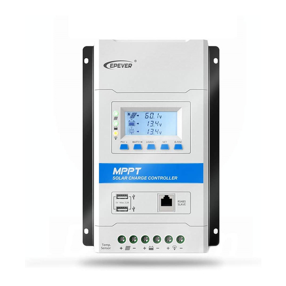
1. General Information 1.1 Overview The TRIRON N series controllers are modular-designed products based on six MPPT solar controller models. The main unit(Power Module)(TRIRON-N) is a solar controller which can be integrated with different display and interface modules to meet a variety of functional requirements. -
Page 8: Characteristics
LCD and indicators to display operating data and status of the system User-friendly buttons for comfortable and convenient operation Master and slave RS485 communication modules design, reading the load or inverter operating data Control the inverter switch through the relay interface ... -
Page 9: Module Types
1.3 Module Types 1-Power Modules The Power Modules control PV battery charging & load discharging without any without any display or interface modules installed –they can operate on their own. If a display or interface module is installed, it will be powered by the Power module and the appropriate module driver will be loaded. - Page 10 LED Indicators: PV & load working status Buttons: View or set the parameters LCD:PV display: voltage/current /generated energy Battery display: voltage/current/temperature Display Load: Standard 1 Display current/load working mode when the controller communicates with the PC or APP. Display voltage/current/ power consumption when the controller communicates with the inverter.
- Page 11 Interface Modules Picture Module Function RS485 interface: Connect to PC or phone. USB COM View or change the controller parameters. USB interface: Slave Supplies 5VDC for electronic equipment. NOTE: USB interface is output when the load is ON. RS485 interface: Connect to inverter.
-
Page 12: Designations Of Controller Models
1.4 Designations of Controller Models EXAMPLE:... -
Page 13: Accessories (Optional)
1.5 Accessories (optional) Acquisition of battery temperature for undertaking temperature compensation of control parameters, the standard length of the cable is 3m (length can be Remote Temperature customized). The RTS300R47K3.81A connects to the port (4 ) on the controller. Sensor (RTS300R47K3.81A) NOTE: The temperature sensor short-circuited or damaged, the controller will be charging or discharging at the default temperature 25 ºC. -
Page 15: Installation Instructions
2. Installation Instructions 2.1 General Installation Notes Please read the entire installation instructions to get familiar with the installation steps before installation. Be very careful when installing the batteries, especially flooded lead-acid battery. Please wear eye protection, and have fresh water available to wash and clean any contact with battery acid. - Page 16 TRIRON1206N/2206N: 36 cell 48 cell 54 cell 60 cell System Voc<23V Voc<31V Voc<34V Voc<38V voltage Max. Best Max. Best Max. Best Max. Best 72 cell Voc<46V 96 cell Voc<62V Thin-Film Module System voltage Voc>80V Max. Best Max. Best NOTE: The above parameter values are calculated under standard test conditions ,Module Temperature 25℃,...
- Page 17 (2) Maximum PV array power This MPPT controller has a limiting function of charging current/power. The charging current/power will be limited within the rated range, therefore, the controller will charge the battery with the rated charging power even if the input power at the PV exceeds this limit.
-
Page 18: Wire Size
WARNING: The controller may be damaged when the maximum PV open circuit voltage(Voc) exceeds 60V(TRIRON**06N), 100V(TRIRON**10N) or 150V (TRIRON**15N) at minimum operating environment temperature. 2.3 Wire Size The wiring and installation methods must conform to all national and local electrical code requirements. -
Page 19: Mounting
NOTE: The wire size is only for reference. If there is a long distance between the PV array and the controller or between the controller and the battery, larger wires can be used to reduce the voltage drop and improve performance. - Page 20 Step 1: Determination of Installation Location and Heat-dissipation Space Figure 2-2 Schematic of wiring diagram Determination of installation location: The controller shall be installed in a place with sufficient air flow through the radiators of the controller and a minimum clearance of 150 mm from the upper and lower edges of the controller to ensure natural thermal convection.
- Page 21 Step 4:Connect accessories Connect the remote temperature sensor cable (model: RTS300R47K3.81A) Connect one end of the remote temperature sensor cable to the interface ③ and place the other end close to the battery. NOTE: If the remote temperature sensor is not connected to the controller,, the default setting for battery charging or discharging temperature is 25 °...
-
Page 22: Install The Modules
3. Install the modules... -
Page 24: Module Introduction
4. Module Introduction 4.1 Display Module 4.1.1 Display Basic1 (DB1) (1)Charging and battery LED indicator Indicator Color Status Information PV connection normal ,but Green On Solid low voltage(low irradiance) from PV, no charging No PV voltage(night time) or Green PV connection problem Green Slowly Flashing(1Hz) In charging... -
Page 25: Display Standard1 (Ds1)
(2)Battery Capacity Level Indicator Battery Capacity Level (BCL) Indicator Color Status Information ○○○ ☆ Green 25% Indicator slowly flashing 0%to <25% 50% Indicator slowly flashing ● ○○ ☆ Green 25%to <50% 25% Indicator on solid 75% Indicator slowly flashing ●●... - Page 26 (1)Charging and load LED indicator Indicator Color Status Instruction PV connection normal but low Green On Solid voltage(low irradiance) from PV, no charging No PV voltage(night time) or PV Green connection problem Green Slowly Flashing(1Hz) Charging Battery Green Fast Flashing(4Hz) PV Over voltage On Solid Load ON...
- Page 27 No charging Charging PV Voltage, Current, Power Battery capacity, In Charging Battery Battery Voltage, Current, Temperature Battery Type Load ON Load Load OFF Load Voltage, Current, Load mode 2) Browse interface 3) Load parameters Combination of the DS1 and RCM modules (To connect the system with the inverter, refer to 4.3.2)
- Page 28 Display:Voltage/Current/Consumed power Combination of the DS2 and UCS modules with the LCD display (connect a LED load: refer to 4.3.2) Display:Current/Consumed power/Load working mode-Timer1/ Load working mode-Timer2 4) Setting ① Clear the generated energy Operating: Step 1: Press the button and hold 5s under the PV power interface and the value is flashing.
-
Page 29: Display Standard 2 (Ds2)
NOTE: Please refer to chapter 5.1 for the battery control voltage, when the battery type is User. ④Local load mode Operating: Step1: Press the button and hold 5s under the load mode interface. Step2: Press the button when the load mode interface is flashing. Step3: Press the button to the load mode. - Page 30 On Solid Over discharged Battery Overheating Slowly Flashing(1Hz) ① Low temperature Yellow On Solid Load ON Yellow Load OFF Controller Overheating PV&BATTLED fast flashing ② System voltage error ①When a lead-acid battery is used, the controller hasn’t the low temperature protection.
- Page 31 Icon Icon Icon Information Information Information Not discharging Not charging Discharging Night Charging 1)PV parameters Display:Voltage/Current/Power/Generated Energy 2)Battery parameters Display:Voltage/Current/Temperature/Battery capacity level 3)Load parameters Combination of the DS2 and RCM modules (To connect the system with the inverter, refer to 4.3.2) Display:Voltage/Current/Power/ Consumed energy/Frequency ...
- Page 32 Display: Voltage/Current/Power/ Consumed energy/Load working mode-Timer1/ Load working mode-Timer2 (4)Setting parameters 1)Battery type Sealed (Default) User Flooded Operation: Step 1: Press the button for the setting interface. Step 2: Press the button and hold 5s the battery type interface. Step 3: Press the button to choose the battery type.
- Page 33 Step 5: Press the button to confirm the parameters. 3)Temperature unit Operation: Step 1: Press the button for the setting interface. Step 2: Press the button and hold 5s for the battery type interface. Step 3: Press the button twice for the temperature units interface. Step 4: Press the button to set the temperature units.
-
Page 34: Interface Modules
Step 1: Press the button for the setting interface. Step 2: Press the button and hold 5s for the load working mode interface. Step 3: Press the button to set the working mode.. Step 4: Press the button to confirm the parameters. NOTE:Please refer to chapter 5.2 for the load working mode. -
Page 35: Relay Com Master (Rcm)
4.2.4 Relay COM Master (RCM) RS485 interface: When the master is set in RS485 communication mode, i.e., with a combination of the RCM and DS1/DS2 modules, the information of the inverter (to be supplied by our company) can be displayed by the DS1/DS2 module. See the following figure: Relay interface: It shall connect the controller’s relay in parallel with the inverter start switch, so it can turn ON/OFF the inverter by operating the button. -
Page 36: Relay Com Slave (Rcs)
4.2.5 Relay COM Slave (RCS) RS485 interface: When the slave is set in RS485 communication mode, i.e., with a combination of the RCS and DS1/DS2 modules, the information of the inverter (to be supplied by our company) can be displayed by the DS1/DS2 module. Relay interface: It shall connect the controller’s relay in parallel with the inverter start switch, so it can turn ON/OFF the inverter by operating the button. -
Page 37: Setting Control Parameters
5. Setting Control Parameters 5.1 Battery types 5.1.1 Support battery types Item Lead-acid battery Lithium battery Sealed(default) (4s/12V; 8s/24V) LiFePO4 Li(NiCoMn)O (3s/12V; 6s/24V) Flooded User(9~34V) User(9~17V/12V; 18~34V/24V) NOTE: When the default battery type is selected, the battery voltage control parameters will be set by default and can’t be changed. To change these parameters, select "User"... -
Page 38: User Settings
5.1.3 User settings 1) PC setting Connection Download software http://www.epever.com (PC Software for the Solar Charge Controller) 2) APP software setting Download software(User for lead-acid battery) http://www.epever.com (Android APP for the Solar Charge Controller) ... -
Page 39: Load Working Modes
Ⅳ. Under Voltage Warning Reconnect Voltage > Under Voltage Warning Voltage ≥ Discharging Limit Voltage. Ⅴ. Boost Reconnect Charging voltage > Low Voltage Disconnect Voltage. The following rules must be observed when modifying the parameters value in User for lithium battery. Ⅰ. -
Page 40: R485 Communication Setting
2) DS2 module display and operation Operation: Step1: Press the button for the setting interface. Step2: Press the button and hold 5s for the load working mode interface. Step3: Press the button to set the load working modes. Step4: Press the button to confirm the parameters. - Page 41 Light ON/OFF Light ON+ Timer Time Control Control the load ON/OFF time through setting the real-time clock. Load working mode settings 2) (1)PC setting Connection Download software http://www.epever.com(PC Software for the Solar Charge Controller)
- Page 42 (2)APP software setting Download software http://www.epever.com(Android APP for the Solar Charge Controller) (3)MT50 Setting NOTE: For detailed setting methods, please refer to the instructions or contact after-sales support.
-
Page 43: Protections, Troubleshooting And Maintenance
6. Protections, Troubleshooting and Maintenance 6.1 Protection When the charging current or power of the PV array exceeds its rated current or power, it will be charged at the rated Over Current current or power. PV Short Circuit When not in PV charging state, the controller will not be damaged in case of a short-circuiting in the PV array. When the polarity of the PV array is reversed, the controller may not be damaged and can continue to operate normally after the polarity is corrected. -
Page 44: Troubleshooting
★When the internal temperature is 81℃, the reducing power charging mode which reduce the charging power of 5%,10%,20%,40% every increase 1 ℃is turned on. If the internal temperature is greater than 85℃, the controller will stop charging. But while the temperature decline to be below 75 º C, the controller will resume. 6.2 Troubleshooting ... - Page 45 When heat sink of controller exceeds 85℃, the controller will Controller automatically cut input and Overheating output circuit. When the PV/BATT(orange)/Battery temperature below 75℃,the capacity lever(four) indicator fast controller will resume to work. flashing ①Check whether the battery DS2: voltage match with the PV/BATT(orange)indicator fast controller working voltage.
-
Page 46: Maintenance
6.3 Maintenance The following inspections and maintenance tasks are recommended at least two times per year for best performance. Make sure controller firmly installed in a clean and dry ambient. Make sure no block on air-flow around the controller. Clear up any dirt and fragments on radiator. -
Page 47: Technical Specifications
7. Technical Specifications Electrical Parameters TRIRON TRIRON TRIRON TRIRON TRIRON TRIRON TRIRON Item 1206N 2206N 1210N 2210N 3210N 4210N 4215N ① System nominal voltage 12/24VDC Auto Rated charge current Rated discharge current Battery voltage range 8~32V ② ② ② 100V 150V Max. - Page 48 Environmental Parameters -25℃~+55℃(LCD) ※ Working environment temperature -30℃~+55℃(No LCD) Storage temperature range -20℃~+70℃ ≤95%, N.C Relative humidity Enclosure IP30 ※ The controller can full load working in the working environment temperature, When the internal temperature is 81℃, the reducing power charging mode is turned on. Refer to P36. Mechanical Parameters TRIRON1206N TRIRON2206N...
-
Page 49: Annex I Conversion Efficiency Curves
Annex I Conversion Efficiency Curves Illumination Intensity: 1000W/m Temp: 25º C Model: TRIRON1206N Solar Module MPP Voltage(17V, 34V) / Nominal System Voltage(12V) 12V Conversion Efficiency Curves 97.00% 96.00% 95.00% 94.00% 93.00% 92.00% 91.00% 90.00% 89.00% 88.00% Charging Power W Solar Module MPP Voltage(34V) / Nominal System Voltage(24V) 24V Conversion Efficiency Curves 98.00% 97.00%... - Page 50 Model: TRIRON2206N 1.Solar Module MPP Voltage(17V, 34V) / Nominal System Voltage(12V) 12V Conversion Efficiency Curves 98.00% 97.00% 96.00% 95.00% 94.00% 93.00% 92.00% 91.00% Charging Power W 2. Solar Module MPP Voltage(34V) / Nominal System Voltage(24V) 24V Conversion Efficiency Curves 98.50% 98.00% 97.50% 97.00%...
- Page 51 Model: TRIRON2210N 1. Solar Module MPP Voltage (17V, 34V,51V) / Nominal System Voltage(12V) 12V Conversion Efficiency Curves 99.00% 97.00% 95.00% 93.00% 91.00% 89.00% 87.00% 85.00% Charging Power W 2. Solar Module MPP Voltage (34V,51V,68V) / Nominal System Voltage(24V) 24V Conversion Efficiency Curves 100.00% 98.00% 96.00%...
- Page 52 Model: TRIRON3210N 1.Solar Module MPP Voltage (17V, 34V,51V) / Nominal System Voltage(12V) 12V Conversion Efficiency Curves 99.00% 97.00% 95.00% 93.00% 91.00% 89.00% 87.00% 85.00% Charging Power W 2. Solar Module MPP Voltage (34V,51V,68V) / Nominal System Voltage(24V) 24V Conversion Efficiency Curves 99.00% 98.00% 97.00%...
- Page 53 Model: TRIRON4210N 1. Solar Module MPP Voltage (17V, 34V,51V) / Nominal System Voltage(12V) 12V Conversion Efficiency Curves 100.00% 98.00% 96.00% 94.00% 92.00% 90.00% 88.00% 100 150 200 300 400 520 600 Charging Power W 2. Solar Module MPP Voltage (34V,51V,68V) / Nominal System Voltage(24V) 24V Conversion Efficiency Curves 100.00% 98.00%...
- Page 54 Model: TRIRON4215N 1. Solar Module MPP Voltage (16.5V, 33V,66V) / Nominal System Voltage(12V) 2. Solar Module MPP Voltage (33V,66V,98V) / Nominal System Voltage(24V)
-
Page 55: Annex Ii Dimensions
Annex II Dimensions TRIRON1206N/TRIRON1210N (Unit: mm) - Page 56 TRIRON2206N/ TRIRON2210N (Unit: mm)
- Page 57 TRIRON3210N (Unit: mm)
- Page 58 TRIRON4210N/ TRIRON4215N (Unit: mm) Any changes without prior notice! Version number: 1.2...
- Page 60 BEIJING EPSOLAR TECHNOLOGY CO., LTD. Tel: +86-10-82894112 / 82894962 Fax: +86-10-82894882 E-mail:info@epsolarpv.com Website: http://www.epsolarpv.com/ http://www.epever.com/...
Need help?
Do you have a question about the TRIRON N Series and is the answer not in the manual?
Questions and answers