Advertisement
Quick Links
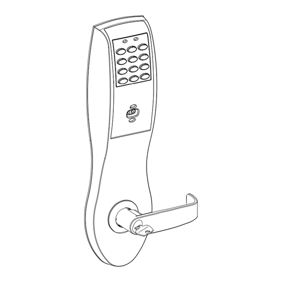
Installation Instructions
For Profile Series v.N1
Cylindrical Lock
A0806B
2/09
Copyright © 2005, 2008, 2009, Sargent Manufacturing Company, an ASSA ABLOY Group company. All rights reserved.
Reproduction in whole or in part without the express written permission of Sargent Manufacturing Company is prohibited.
Available through Authorized Channel Partners only.
Contact your local ASSA ABLOY Door Security Solutions
sales consultant for details.
Advertisement

Subscribe to Our Youtube Channel
Related Manuals for Sargent ASSA ABLOY Profile Series


Summary of Contents for Sargent ASSA ABLOY Profile Series
- Page 1 Contact your local ASSA ABLOY Door Security Solutions sales consultant for details. A0806B 2/09 Copyright © 2005, 2008, 2009, Sargent Manufacturing Company, an ASSA ABLOY Group company. All rights reserved. Reproduction in whole or in part without the express written permission of Sargent Manufacturing Company is prohibited.
-
Page 2: Table Of Contents
Table of Contents Page Warning General Description ................1 Features ....................1 Specifications ..................2 Parts Breakdown ................3-5 Installation Instructions ..............5-9 Electrical Installation Guidelines ..........10-13 Mechanical Operational Check ............14 Electrical Operational Check ............. 14 Warning Warning: Changes or modifications to this unit not expressly approved by the party responsible for compliance could void the user’s authority to operate the equipment. -
Page 3: General Description
Profile Series v.N1 Cylindrical Lock General Description The Profile Series v.N1 Access Control product integrates into any Wiegand based access control system and consists of door hardware and an Interface Module offered in 2 and 4 door configurations. Features • Complete monitoring of door from locks • 12 or 24 VDC • I nterface Module connects to most third party • H ID 125khz standard Wiegand bit format proximity... -
Page 4: Specifications
Profile Series v.N1 Cylindrical Lock Specifications • Stainless steel, 3⁄4” projection, one-piece • Inside lever retracts latch • Guardbolt - Stainless steel, non-handed • Locks furnished for 1-3/4” doors. Can be furnished for other door sizes upon request. • H anded Consult factory • O utside lever controlled by any combination of • U.L. Listed (3 hr.) keypad or proximity Electrical Operating Voltage 12 or 24 VDC Controller : 46mA (Max) / Interface Module : 182mA (Max) Aux Relay Board : 386mA (Max) Current Draw All 12 VDC Lockbodies : 500mA (Max) All 24 VDC Lockbodies : 250mA (Max) Relay Contacts 12-24VAC/DC; 1A (max) Cable Data A, Data B Cable RS 485 Capable... -
Page 5: Parts Breakdown
Profile Series v.N1 Cylindrical Lock Parts Breakdown A0806B • 800-810-WIRE (9473) • www.sargentlock.com... - Page 6 Profile Series v.N1 Cylindrical Lock Parts Breakdown (Continued) ITEM PART No. DESCRIPTION REQ’D 10-2000 2-3/4” Backset Latch (Standard) 10-2053 3-3/4” Backset Latch (23 Prefix) 10-2058 5” Backset Latch (25 Prefix) 10-2634 3/4” Throw (41 Prefix) *10-3016 Outside Escutcheon Housing Only 52-2431 Proximity Only Bezel w/ Harness 52-2432 Key Pad / Proximity Bezel w/ Harness 52-3351 Controller Assembly *10-3015 Inside Escutcheon Housing Only 10-0523 “B” Inside Lever/Passage 10-2204 “J” Inside Lever/Passage NOTE: Coastal Levers &...
-
Page 7: Installation Instructions
• P repare door according to appropriate template(s): – Field door templates are shipped with product – Door manufacturer’s templates 4531 (inside) and 4532 (outside) – Raceway template 4540 (for wood and metal doors) • F or replacement templates, contact SARGENT 1-800-810-WIRE (9473). Inside Outside of door of door (2) 1/8” Dia. holes... - Page 8 Step #2 – Concealed Door Position Switch (3287) Installation Instructions Centerline of latch front and Door position switch wiring information: strike Install the SARGENT 3287 Concealed Door Status Switch with this v.N1 10 Line Product, using SARGENT installation document A7448B. Screws (2) #8-32 x 3/4" Wire the 3287 Concealed Door Status Switch to the ElectroLynx frame harness and to the door status wires: 1. Connect the common wire of the switch to the common wire of the harness.
- Page 9 Profile Series v.N1 Cylindrical Lock Step #5 – Lock Installation For lock installation: • Lock through bolts are preset to 12 and 6 o’clock. • Rotate outside rose to match door. • Remove and re-align spacer busing to fit into back of lever. Through bolt holes 1-3/4" thick door Spacer bushing 2" thick door Lockbody holes Rotate to match through bolt holes in door Fig.
- Page 10 Profile Series v.N1 Cylindrical Lock Step #6 – Prepare Frame and Install Strike 1A. If this is a wood door, feed wires up through the routed channel (Fig. 6A - 1A). 1B. If this is a metal door (not shown), feed wire and connector through inside of door and out the hole on the outside of the door.
- Page 11 Profile Series v.N1 Cylindrical Lock Step #9 – Installation of Outside Escutcheon and Lever Note: For exterior applications, use weather seal gasket (part number 10-0469) between escutcheon and outside door surface. 1A. For fire rated doors only, feed ribbon cable connector and ground wire from outside of door through weather seal gasket (if used). Then, feed through fire stop plate. 1B. For non-fire rated doors only, feed ribbon cable connector and ground wire from outside of door through weather seal gasket (if used). Then install conduit sleeve in door.
-
Page 12: Electrical Installation Guidelines
Profile Series v.N1 Cylindrical Lock Electrical Installation Guidelines Power and Door Wiring This diagram depicts the power and door wiring of the v.N1 system. Earth ground and power supply ground must be common between the power supplies that power the v.N1 components and the electronic access control system; however, these grounds must not be common to each other. The wiring for each door consists of five connections between the interface module and the controller inside of the door. - Page 13 Profile Series v.N1 Cylindrical Lock Electrical Installation Guidelines (Continued) Specific Door Wiring This diagram depicts the specific door wiring of the v.N1 System. The wiring from the Interface Module to the door should conform to the guidelines specified in the v.N1 User Manual A7817: • Data A and Data B are RS485 and should be run on their own shielded cable. • The shield should be terminated at EGND at the interface module. • T he remaining three signals should be run in their own cable and terminate in a junction location along with data wires A and B and the door position input.
- Page 14 Profile Series v.N1 Cylindrical Lock Electrical Installation Guidelines (Continued) Interface Module The interface module is an integral part of v.N1 architecture. The diagram on the following page provides common locations of installation and should clarify integration confusion. Note: For a complete guide to all external connections, refer to the v.N1 User Manual (document number A7817). 1) TS2 and TS3 provide physical connection points to each door. If using power supplied by the interface board, all five connections are necessary. If not, DO NOT connect a 12V (or 24V) signal. These connections are, from top to bottom, in reverse order on each side of the board.
- Page 15 Profile Series v.N1 Cylindrical Lock Electrical Installation Guidelines (Continued) Interface Module A0806B • 800-810-WIRE (9473) • www.sargentlock.com...
-
Page 16: Mechanical Operational Check
Profile Series v.N1 Cylindrical Lock Mechanical Operational Check For devices with cylinders: 1. Insert key into cylinder and rotate. 2. Ensure that the key retracts the latch. 3. Ensure that the key rotates freely. 4. Ensure that the inside lever retracts latch. Electrical Operational Check 1. Configure the lock to display the red LED when locked. The red LED should be present, if powered. 2. I f the red LED is present, the door should be locked. If that is not the case, check the fail safe / fail secure configuration on the controller. 3. When wired to the interface module, LED 3 on the interface module should flash rapid and green. 4. I f a short circuit is supplied across LOCK terminals on the appropriate integration connector on the interface module (TS4, TS5, TS6, TS7), the door should unlock. Hardwiring Made Easy™... - Page 17 Profile Series v.N1 Cylindrical Lock Notes A0806B • 800-810-WIRE (9473) • www.sargentlock.com...
- Page 18 Copyright © 2005, 2008, 2009, Sargent Manufacturing Company, an ASSA ABLOY Group company. All rights reserved. Reproduction in whole or in part without the express written permission of Sargent Manufacturing Company is prohibited. ASSA ABLOY is the global leader in door opening solutions, dedicated to A0806B-2/09 satisfying end-user needs for security, safety and convenience.
Need help?
Do you have a question about the ASSA ABLOY Profile Series and is the answer not in the manual?
Questions and answers