Advertisement
Quick Links
A8028E
06/17
Copyright © 2017, Sargent Manufacturing Company, an ASSA ABLOY Group company.
All rights reserved. Reproduction in whole or in part without the express written
permission of Sargent Manufacturing Company is prohibited.
H2
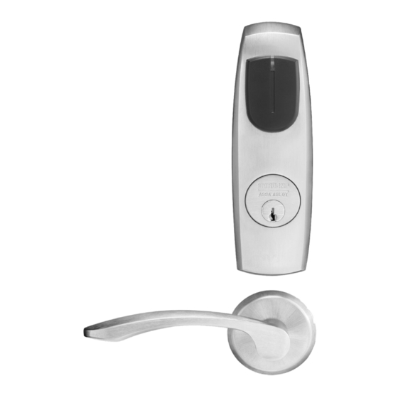
Harmony Series
Cylindrical Lock
with iCLASS SE
Installation Instructions
Reader
®
Advertisement

Subscribe to Our Youtube Channel
Related Manuals for Sargent ASSA ABLOY Harmony Series


Summary of Contents for Sargent ASSA ABLOY Harmony Series
- Page 1 SE Reader ® Installation Instructions A8028E 06/17 Copyright © 2017, Sargent Manufacturing Company, an ASSA ABLOY Group company. All rights reserved. Reproduction in whole or in part without the express written permission of Sargent Manufacturing Company is prohibited.
-
Page 3: Table Of Contents
Any retrofit or other field modification to a fire rated opening can potentially impact the fire rating of the opening, and SARGENT Manufacturing makes no representations or warranties concerning what such impact may be in any specific situation. When retrofitting any portion of an existing fire rated opening, or specifying and installing a new fire-rated opening, please consult with a code specialist or local code official (Authority Having Jurisdiction) to ensure compliance with all applicable codes and ratings. -
Page 4: General Description
® ® Backed by SARGENT’s Grade 1 hardware, the Harmony series cylindrical lock comes with Request to Exit (RX) monitoring inside the lockbody and is available in 12 or 24VDC. The Harmony H2 iCLASS SE reader provides visual (LED) and audible indicators of lock state (locked/unlocked). -
Page 5: Wiring Diagrams
1-Black 2-Red 3-White 4-Green 5-Orange 6-Blue 7-Brown 8-Yellow 1-Violet 2-Gray 3-Pink 4-Tan ACCESS CONTROL DEVICES: Harmony H2, ElectroLynx wire Color / Function assignments SARGENT - 12/24VDC WIE- WIE- EGND 12/24 VDC GAND GAND (NC) (COM) HARMONY (Reader) (LOCK RELAY) SERIES... - Page 6 Harmony Series H2 Cylindrical Lock Typical Harmony Cylindrical Lock Application Diagram (12/24VDC Lock) MODE 1: RED LED ‘ON’ WHEN POWERED Standard Application Shown - For Alternative Applications Contact 1-800-810-WIRE (9473) Reader Electronics Require 12 or 24VDC UL294 Listed, Power Limited Power Supply (or UL603) 12VDC System 24VDC System •...
-
Page 7: Parts Breakdown
Harmony Series H2 Cylindrical Lock Parts Breakdown Lever Hand Reverse Door Prior to installation, please confirm receipt of all parts. *Adapter Plate is only shipped with orders that specify 1-3/8” doors. Tools Required: *If you are replacing iCLASS-only product: • Replace both reader &... - Page 8 Harmony Series H2 Cylindrical Lock Parts Breakdown (Continued) Lever Hand Reverse Door ITEM PART # DESCRIPTION REQ. ITEM PART # Description Req. (82) CYL Lock bodies H2-EM01CL-[xxx**] Outside Escutcheon Assembly 10-3384 10G 270-24V Fail Safe Lock body Assembly 52-0792 Outside Gasket 52-0791 Inside Gasket 10-3388 10G 271-24V Fail Secure Lock body Assembly...
-
Page 9: Installation Instructions
Harmony Series H2 Cylindrical Lock Installation Instructions 1 Door Preparation A. Verify Hand and Bevel of Door Stand on outside of locked door when determining door hand. Left Hand Left Hand Right Hand Right Hand Hinges Left. Reverse Bevel Hinges Right. Reverse Bevel Open Inward. - Page 10 Control System System integrator will determine the use and installation location. 2. If SARGENT 3287 Concealed DPS installation is specified, use SARGENT template A7448 to prepare the door and frame at desired location. 3. Wire the 3287 Concealed DPS to the ElectroLynx frame harness to the door position switch wires.
- Page 11 Harmony Series H2 Cylindrical Lock 5 Lock Installation A. Lock Preset • Lock body holes – 12 and 6 o’clock (Fig. 5A) Outside of Door • Door thickness – 1-3/4” thick (refer to B for minor adjustments) Through-bolt Holes B. Through-bolt Minor Adjustments •...
- Page 12 Harmony Series H2 Cylindrical Lock 6 Secure Lock to Door 1. Feed wire and connector: • For wood door, feed connectors and wires through the door and up the wire run channel (Fig. 6A). • For metal door (not shown), feed connectors and wires into the lockbody hole and out the controller hole. 2.
- Page 13 Harmony Series H2 Cylindrical Lock 7 Lever and Cylinder Removal (If Necessary) Standard Cylinder 1. Insert key, rotate 45° clockwise and hold (Fig. 7A). 2. Depress lever retainer with push pin tool (provided). 3. Reverse this procedure to reassemble. Fig. 7A Note: Be sure spacer is installed on the back of cylinder plug.
- Page 14 Harmony Series H2 Cylindrical Lock 9 Installation of Outside Escutcheon and Lever and Gaskets Outside of Door Outside of Door 1. Feed the reader cable connector located on the back of the outside es- cutcheon from the outside of the door Escutcheon Screws #8-32 X 2”...
- Page 15 Harmony Series H2 Cylindrical Lock 10 Installing Controller 1. Feed controller harness earth ground into and around behind rim of large upper hole of the mounting plate (Fig. 10A, B). Inside of Door Controller PCB Earth ground Inside of Door Fig.
- Page 16 Harmony Series H2 Cylindrical Lock 10 Installing Controller (Continued) Install Controller Please follow these steps prior to installing inside escutcheon to prevent any damage caused by pinching wires: 1. Once wires are arranged, position controller at a rotated angle against the door, under the earth ground wire.
- Page 17 Harmony Series H2 Cylindrical Lock 12 Inside Escutcheon and Lever 1. Feed wires into door prep. 2. Insert #8-32 x 5/8” Phillips flat head escutcheon screws and thread into mounting plate. 3. Position inside escutcheon against door. Note: Be sure not to cover but not pinch wires when mounting escutcheon.
-
Page 18: Operational Check
Harmony Series H2 Cylindrical Lock Operational Check For devices with cylinders: 1. Insert key into cylinder and rotate: The key will retract the latch. The key should rotate freely. 2. Ensure inside lever retracts latch. 3. Close door: Ensure latch is fully extended and does not bind. - Page 20 New Haven, CT 06511 USA 800-727-5477 • www.sargentlock.com Founded in the early 1800s, SARGENT® is a market leader in locksets, cylinders, door closers, exit devices, electro-mechanical products and access control systems for new construction, renovation, and replacement applications. The company’s customer base includes commercial construction, institutional, and industrial markets.
Need help?
Do you have a question about the ASSA ABLOY Harmony Series and is the answer not in the manual?
Questions and answers