Advertisement
Advertisement

Subscribe to Our Youtube Channel
Related Manuals for Sargent ASSA ABLOY SE LP10


Summary of Contents for Sargent ASSA ABLOY SE LP10
- Page 1 SE LP10 Cylindrical Lock Installation Instructions A8117G(M1) 05/20 Copyright © 2020, Sargent Manufacturing Company, an ASSA ABLOY Group company. All rights reserved. Reproduction in whole or in part without the express written permission of Sargent Manufacturing Company is prohibited.
-
Page 2: Table Of Contents
SE LP10 Cylindrical Lock Table of Contents Regulatory Compliance ............3 Warning ................. 3 General Description .............. 5 Specifications/Features ............5 Parts Breakdown ..............7 Wiring Diagrams ..............10 Installation Instructions ............. 12 Operational Check .............. 20 A8117G • 800-810-WIRE (9473) • www.sargentlock.com... -
Page 3: Regulatory Compliance
Pour plus d’informations, visitez: www.P65warnings.ca.gov. Any retrofit or other field modification to a fire rated opening can potentially impact the fire rating of the opening, and SARGENT Manufacturing makes no representations or warranties concerning what such impact may be in any specific situation. When retrofitting any portion of an existing fire rated opening, or specifying and installing a new fire-rated opening, please consult with a code specialist or local code official (Authority Having Jurisdiction) to ensure compliance with all applicable codes and ratings. -
Page 4: General Description
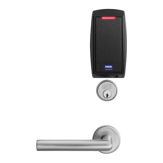
SE LP10 Cylindrical Lock General Description The SARGENT SE LP10 brings flexibility to our Integrated Wired access control solutions. Featuring multiCLASS SE Technology from HID Global , the SE LP10 is ideal for mixed ® ® credential environments and enables easy migration to higher security credentials and mobile access. - Page 5 SE LP10 Cylindrical Lock Specifications / Features (Continued) • UL Listed* - UL 294 Indoor Use • UL 294 Access Control Ratings: • CUL Listed - S319: Class 1 Destructive Attack Level 1 • ANSI/BHMA A156.25 Listed Line Security Level 1 Grade 1 Compliant Endurance Level 4...
-
Page 6: Parts Breakdown
SE LP10 Cylindrical Lock Parts Breakdown Tools Required: • #2 Phillips screwdriver • Push pin (provided) • T10 Torx Driver • 3/32” drill bit • 3/4” drill bit • 5/16” drill bit • 3/8” drill bit • 7/16” drill bit •... - Page 7 SE LP10 Cylindrical Lock Parts Breakdown (Continued) 11 * Adapter Plate/Spacer (10-0847) is only shipped with orders that specify 1-3/8” doors. ITEM PART # DESCRIPTION REQ. Refer to SE LP10 Catalog for Available Lever Styles Refer to SE LP10 Catalog for Available Cylinders 10-3049 Outside Rose Spring Assembly 10-0850...
- Page 8 SE LP10 Cylindrical Lock Parts Breakdown (Continued) ITEM PART # DESCRIPTION (STD, 10, 10-21, 11, 11-21, 21, 22, SC, SE, VA, VS) CYL Lockbodies 10-3360 10G270-24V Fail Safe Lock body Assembly 10-3364 10G271-24V Fail Secure Lock body Assembly 10-3361 10G270-12V Fail Safe Lock body Assembly 10-3365 10G271-12V Fail Secure Lock body Assembly (60, 63, 64) CYL Lockbodies...
-
Page 9: Wiring Diagrams
2-Red 3-White 4-Green 5-Orange 6-Blue 7-Brown 8-Yellow 1-Violet 2-Gray 3-Pink 4-Tan ACCESS CONTROL DEVICES: SE LP10 Cylindrical, ElectroLynx wire Color / Function assignments SARGENT - 12VDC WIEGAND WIEGAND EGND TAMPER 12/24 VDC SE LP10 (Reader) (LOCK RELAY) GREEN_LED* Cylindrical DATA_1... - Page 10 SE LP10 Cylindrical Lock Typical (UL294-Compliant) SE LP10 Cylindrical Application Diagram #1 Tamper will trigger when reader is removed from door and tamper wiring is connected at the panel. 12/24VDC System Average Peak Average Peak Reader 100mA 220mA Actuator 15mA 500mA 15mA 500mA...
- Page 11 SE LP10 Cylindrical Lock Alternate Indicator Cylindrical Application Diagram #2 (12/24VDC System) Connect GREEN_LED input to switch controlled by panel. Shorting GREEN_LED to READER_NEG (Black) with panel switch will override reader LED to keep it green. 12/24VDC System Average Peak Average Peak Reader...
-
Page 12: Installation Instructions
SE LP10 Cylindrical Lock Installation Instructions 1 Door Preparation A. Verify Hand and Bevel of Door Stand on outside of locked door when determining door hand. Left Hand Left Hand Right Hand Right Hand Hinges Left. Reverse Bevel Hinges Right. Reverse Bevel Open Inward. - Page 13 Use SARGENT 3287 Concealed Door Position Switch with this Control System SE LP10 10-Line Product: 1. Install the 3287 Concealed Door Position Switch described in SARGENT document A7448B. 2. Wire the 3287 Concealed Door Position Switch to the ElectroLynx frame harness to the door position switch wires.
- Page 14 SE LP10 Cylindrical Lock 5 Install Reader Backplate and (Optional*) Fire Shield or Gasket 1. For fire-rated doors only, install reader backplate and fire shield to door using two (2) #8-18 x 5/8” Phillips flat head self-drilling screws (Fig. 5A). 2.
- Page 15 SE LP10 Cylindrical Lock 6 Installation of SE LP10 Reader and Trim Bezel Observe precautions for handling electrostatic sensitive devices. If removing (or installing) the SE LP10 reader harness/module (Fig. 6A), make sure that the reader is powered down before inserting/removing the harness/module.
- Page 16 SE LP10 Cylindrical Lock 7 How to Remove Outside Lever (If Necessary) 1. Insert key, rotate 45° clockwise and hold Outside of Door (Fig. 7A, B). 2. Depress lever retainer with push pin tool (provided). 3. Reverse this procedure to reassemble. Note: Be sure spacer is installed on the back of cylinder plug.
- Page 17 SE LP10 Cylindrical Lock 9 Install Lock Body (Continued) C. Install Lock: 1. Feed wires into the lock body hole, from outside of door (Fig. 9B). 2. With outside lever horizontal, insert the mounting post through outside of door and lock body. Inside of Door (Wood) NOTE: Make certain the lever spindle is properly...
- Page 18 SE LP10 Cylindrical Lock 11 Wire Connections Do not offset connectors and ensure that they are completely seated. 1. Connect 6-pin connector from lock body to 6-pin connector on reader harness (Fig. 11A). 2. Connect 2-pin connector from lock body to 2-pin connector on reader harness (Fig. 11A). Fig.
- Page 19 SE LP10 Cylindrical Lock 12 Fire Plate Installation and Earth Ground Connection 1. Remove lower left screw from mounting plate. Feed screw through green/yellow ground wire ring terminal. Reinstall screw. Ensure that green/yellow wire points toward top of door in order to avoid interference with escutcheon. 2.
-
Page 20: Operational Check
SE LP10 Cylindrical Lock Operational Check 1. Insert key into cylinder and rotate: The key will retract the latch. The key should rotate freely. 2. Ensure inside lever retracts latch. 3. Close door: Ensure latch is fully extended and does not bind. Wiegand Test Unit Feature The ASSA ABLOY Wiegand Test Unit verifies your installation in... - Page 21 SE LP10 Cylindrical Lock Operational Check (Continued) Note: Once electrical wiring has been successfully completed according to proper application, perform the following steps: 1. Ensure lock is interfaced with Wiegand Test Unit to verify installation & wiring up to (frame side) point of hinge. 2.
- Page 22 SE LP10 Cylindrical Lock Notes A8117G • 800-810-WIRE (9473) • www.sargentlock.com...
- Page 24 © Reproduction in whole or in part without the express written permission of Sargent Manufacturing Company is prohibited. HID, the HID logo, iCLASS SE, iCLASS, and Edge are trademarks or registered trademarks of HID Global in the U.S. and/or other countries.
Need help?
Do you have a question about the ASSA ABLOY SE LP10 and is the answer not in the manual?
Questions and answers