Table of Contents
Advertisement
Quick Links
SIMATIC CC7
SIMATIC
Industrial Ethernet - CloudConnect
SIMATIC CC7
Operating Instructions
SIMATIC CloudConnect 712 (6GK1411-1AC00)
SIMATIC CloudConnect 716 (6GK1411-5AC00)
10/2019
C79000-G8976-C503-02
Preface
Application and functions
LEDs, Connectors, Buttons,
CLP
Installation, wiring,
commissioning
Configuration
Diagnostics and
maintenance
Technical specifications
Approvals
Dimension drawings
Accessories
Escape sequences
Syslog messages
1
2
3
4
5
6
7
8
A
B
C
Advertisement
Table of Contents

Related Manuals for Siemens SIMATIC CloudConnect CC7 Series


Summary of Contents for Siemens SIMATIC CloudConnect CC7 Series
- Page 1 SIMATIC CC7 Preface Application and functions LEDs, Connectors, Buttons, SIMATIC Installation, wiring, commissioning Industrial Ethernet - CloudConnect SIMATIC CC7 Configuration Diagnostics and maintenance Operating Instructions Technical specifications Approvals Dimension drawings Accessories Escape sequences Syslog messages SIMATIC CloudConnect 712 (6GK1411-1AC00) SIMATIC CloudConnect 716 (6GK1411-5AC00) 10/2019 C79000-G8976-C503-02...
- Page 2 Note the following: WARNING Siemens products may only be used for the applications described in the catalog and in the relevant technical documentation. If products and components from other manufacturers are used, these must be recommended or approved by Siemens. Proper transport, storage, installation, assembly, commissioning, operation and maintenance are required to ensure that the products operate safely and without any problems.
-
Page 3: Preface
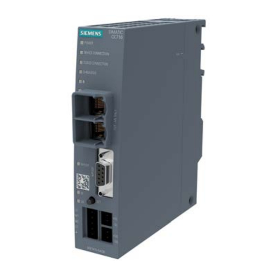
Preface CAUTION To prevent injury, read the manual before use. Products This document contains information on the following products: SIMATIC CC712 / SIMATIC CC716 Hardware product version 1 Firmware version V1.2 Gateway for connection of a SIMATIC S7 or Modbus station to a cloud system, OPC UA server for SIMATIC S7 data Figure 1 SIMATIC CC716... - Page 4 Preface Purpose of the manual This manual describes the properties of the modules and shows application examples. It supports you when installing, connecting up and commissioning the modules. The required configuration steps are described. You will also find instructions for operation and information about the diagnostics options.
- Page 5 Replaced edition Edition 05/2019 Current edition of the manual and application example on the Internet You can find the current version of this manual on the Internet pages of Siemens Industry Online Support: Link: (https://support.industry.siemens.com/cs/ww/en/ps/25621/man) You can find an application example here: Link: (https://support.industry.siemens.com/cs/ww/en/view/109766675)
- Page 6 The firmware is signed and encrypted. This ensures that only firmware created by Siemens can be downloaded to the device. Device defective If a fault develops, please send the device to your SIEMENS service center for repair. Repairs on-site are not possible. Recycling and disposal The product is low in pollutants, can be recycled and meets the requirements of the WEEE directive 2012/19/EU "Waste Electrical and Electronic Equipment".
-
Page 7: Table Of Contents
Table of contents Preface ..............................3 Application and functions ........................11 Application ..........................11 Functions and communication services .................. 11 Configuration examples ......................13 Other services and properties ....................17 Configuration limits - communication ..................18 Range of functions of the WBM ....................19 Scope of delivery and requirements .................. - Page 8 Table of contents 4.4.3 Log out ........................... 55 Start page ..........................55 4.5.1 Info ............................55 Interface configuration ......................56 4.6.1 Ethernet ..........................56 4.6.2 PROFIBUS (CC716) ......................58 4.6.3 DI/DO (CC716)........................62 Process access ........................63 4.7.1 Station configuration ......................63 OPC UA ..........................
- Page 9 Table of contents Technical specifications ........................125 Technical specifications - CloudConnect 712 ............... 125 Technical Specifications - CloudConnect 716 ..............126 Pinout of the Ethernet interfaces ..................128 Pinout of the D-sub socket ....................129 Permitted cable lengths - Ethernet ..................129 Permitted cable lengths - Gigabit Ethernet ................
- Page 10 Table of contents SIMATIC CC7 Operating Instructions, 10/2019, C79000-G8976-C503-02...
-
Page 11: Application And Functions
Application and functions Application Applications of the gateway The gateway connects process stations to the following target systems: ● A cloud system via MQTT Connecting process stations: – S7 Ethernet (CC712 / CC716) – S7 PROFIBUS (CC716) – Modbus/TCP (CC712 / CC716) ●... - Page 12 The cloud access ("Cloud profile") of the gateway is adapted to communication with the following cloud systems and supports the listed services and functions: ● MindSphere (Siemens) Service: MindConnect IoT Extension Function: Publisher ●...
-
Page 13: Configuration Examples
Application and functions 1.3 Configuration examples The OPC UA server supports the functions relevant for this profile from the following specifications: ● IEC/TR 62541-1 (08-2012) OPC Unified Architecture - Part 1: Overview and Concepts ● IEC/TR 62541-2 (02-2009) OPC Unified Architecture - Part 2: Security Model For the supported security profiles, refer to the section OPC UA Security (Page 70). - Page 14 Application and functions 1.3 Configuration examples Configuring a CC712 The process station is a SIMATIC S7-300 in this example. It can also be any other station from the S7 product family. Figure 1-1 CloudConnect 712: Connection of a station to the cloud SIMATIC CC7 Operating Instructions, 10/2019, C79000-G8976-C503-02...
- Page 15 Application and functions 1.3 Configuration examples Configuring a CC716 You can connect up to 7 stations over Ethernet or PROFIBUS using the CC716 gateway. The gateway transfers the data to a cloud broker using MQTT. The example shows an S7-300 connected over Ethernet, an S7-1200 and an S7-400 connected over PROFIBUS.
- Page 16 Application and functions 1.3 Configuration examples Connection of a process stations to OPC UA clients Configuring a CC712 In the configuration shown, the CC712 gateway transfers process data of an S7 station over OPC UA to a central control room or one or more OPC UA clients. The gateway reads process data from the S7 station and, as OPC UA server, makes it available to one or more OPC UA clients.
-
Page 17: Other Services And Properties
Application and functions 1.4 Other services and properties Other services and properties Other services and properties ● IP configuration – The gateway supports IP addresses according to IPv4. IPv6 is supported in addition at the cloud interface. For details, see section Ethernet (Page 56). -
Page 18: Configuration Limits - Communication
Application and functions 1.5 Configuration limits - communication Configuration limits - communication The gateway supports the following maximum quantity structure. Connection resources over the process interface ● Number of connections to S7 stations – CC712: Max. 1 S7 connection to one S7 connection –... -
Page 19: Range Of Functions Of The Wbm
Application and functions 1.6 Range of functions of the WBM ● Number of supported subscriptions Max. 5 subscriptions per session In total maximum of 50 subscriptions at the same time ● Number of items per subscription Max. 500 tags per subscription Max. -
Page 20: Scope Of Delivery And Requirements
Application and functions 1.7 Scope of delivery and requirements Reusing the configuration file The configuration data you create in the WBM is saved in the gateway. If you want to back up the data as well, you can also save the configuration data in the WBM area "Maintenance"... - Page 21 Application and functions 1.7 Scope of delivery and requirements Communication partner ● Process access For process access you need a station in productive operation, alternatively: – S7 station – Modbus station ● Cloud access / OPC clients – For cloud access, you need the access set up to a cloud broker. –...
- Page 22 Application and functions 1.7 Scope of delivery and requirements ● OPC UA: Components of the identifier During configuration, note that the following names are used as part of the identifier in the NodeId of a tag: – CPU name – Name of the DB tag ●...
-
Page 23: Leds, Connectors, Buttons, Clp
LEDs, Connectors, Buttons, CLP LEDs The LEDs on the front show the states of the module. The LED symbols in the table below correspond to the following states of the LEDs: LED symbol LED status ON (steady light) * Flashing : Part flashes yellow and part lit green Meaning of the LED displays LED name... - Page 24 LEDs, Connectors, Buttons, CLP 2.1 LEDs LED name LED pattern Meaning / Module status (colors) Cloud Connection Connection to Cloud (green / yellow) No connection to cloud server Existing connection to cloud server Connection establishment to cloud server No communication with cloud server. Possible causes: Incorrect configuration •...
-
Page 25: Connections
LEDs, Connectors, Buttons, CLP 2.2 Connections Connections 2.2.1 Ethernet interfaces P1/P2 Ethernet interfaces The gateway has two Ethernet interfaces according to Gigabit standard IEEE 802.3ab, designed as RJ45 socket. ● P1 Cloud interface for connection of a cloud broker and OPC clients ●... -
Page 26: Digital Input / Output (Cc716)
LEDs, Connectors, Buttons, CLP 2.2 Connections 2.2.3 Digital Input / Output (CC716) The CC716 gateway has a digital input and a digital output. They can be used as follows: ● Digital Input The input can be used alternatively as a trigger for the following functions: –... -
Page 27: External Power Supply
LEDs, Connectors, Buttons, CLP 2.2 Connections Digital output The output is a switch that switches the signal at +DO to -DO. 2.2.4 External power supply External power supply The connector (socket) for the external 24 V DC power supply is located on the front of the gateway. -
Page 28: The Button "Set
LEDs, Connectors, Buttons, CLP 2.3 The button "SET" Figure 2-1 Socket of the external power supply For information on allocation of the socket and for the connection, see section Connecting (Page 40). You will find further data on the power supply in section Technical specifications (Page 125). The button "SET"... -
Page 29: Clp Slot
LEDs, Connectors, Buttons, CLP 2.4 CLP Slot Pressing the button Duration of pressing Function and operation the button (seonds) ≥ 5 s Resetting to factory settings 1. Turn off the power supply. 2. Switch the power supply on again while pressing the button. Hold down the button for at least 5 seconds during startup. - Page 30 LEDs, Connectors, Buttons, CLP 2.4 CLP Slot SIMATIC CC7 Operating Instructions, 10/2019, C79000-G8976-C503-02...
-
Page 31: Installation, Wiring, Commissioning
Installation, wiring, commissioning Important notes on using the device Safety notices on the use of the device Note the following safety notices when setting up and operating the device and during all associated work such as installation, connecting up or replacing the device. WARNING If the device is installed in a cabinet, the inner temperature of the cabinet corresponds to the ambient temperature of the device. -
Page 32: Notes On Use In Hazardous Areas According To Atex / Iecex
Notes on use in hazardous areas according to ATEX / IECEx WARNING DIN rail In the ATEX and IECEx area of application only the Siemens DIN rail 6ES5 710-8MA11 may be used to mount the modules. WARNING Requirements for the cabinet/enclosure... -
Page 33: General Notices On Use In Hazardous Areas According To Ul Hazloc / Fm
Installation, wiring, commissioning 3.1 Important notes on using the device WARNING Take measures to prevent transient voltage surges of more than 40% of the rated voltage. This is the case if you only operate devices with SELV (safety extra-low voltage). WARNING LAN connection (Local Area Network) A LAN or LAN segment with all the interconnected devices should be contained completely... -
Page 34: Installation
Installation, wiring, commissioning 3.2 Installation WARNING Explosion hazard Do not disconnect equipment when a flammable or combustible atmosphere is present. WARNING EXPLOSION HAZARD The equipment is intended to be installed within an ultimate enclosure. The inner service temperature of the enclosure corresponds to the ambient temperature of the module. Use installation wiring connections with admitted maximum operating temperature of at least 30 ºC higher than maximum ambient temperature. - Page 35 – DIN rail – S7-1500 standard rail – S7-300 standard rail You can find suitable standard rails in the Siemens accessories program for automation technology, for example: 35 mm standard mounting rail for 19" cabinets, article numbers 6ES5710-8MA11 ● Mounting on pedestal You can use the SCALANCE M pedestal 6GK5898-8MD00 for table mounting (does not ship with the product).
- Page 36 Installation, wiring, commissioning 3.2 Installation Installation location NOTICE Installation location - Dependency of the temperature range Note the dependency of the permitted temperature range of the installation location. • Horizontal installation of the rack (DIN rail) means a vertical position of the modules. •...
- Page 37 Installation, wiring, commissioning 3.2 Installation Wall mounting 1. Prepare the drill holes for wall mounting. For the dimensions, refer to the section "Dimension drawings (Page 135)". 2. Secure the device to the wall with two screws (4 mm). SIMATIC CC7 Operating Instructions, 10/2019, C79000-G8976-C503-02...
- Page 38 Protecting the modules from slipping on the DIN rail If you install the modules in an area with mechanical load, use suitable clamping devices at both ends of the device group to secure the modules on the DIN rail, e.g. Siemens and retainer 8WA1808.
- Page 39 Installation, wiring, commissioning 3.2 Installation Mounting on pedestal ① 1. Insert the device with the bottom housing guide on the top edge of the pedestal 2. Press the device against the pedestal until the mounting rail release audibly locks in place ②...
-
Page 40: Connecting
Installation, wiring, commissioning 3.3 Connecting Connecting WARNING Safety Extra-Low Voltage (SELV) by a Limited Power Source (LPS) The equipment is designed for operation with Safety Extra-Low Voltage (SELV) by a Limited Power Source (LPS). This means that only SELV / LPS complying with IEC 60950-1 / EN 60950-1 / VDE 0805-1 must be connected to the power supply terminals. - Page 41 Installation, wiring, commissioning 3.3 Connecting ● In other areas, the fuse must meet the following requirements: – Suitable for DC (min. 60 V / max. 3 A) – Breaking current > highest possible current of the current source (incl. short circuit current and fault) –...
- Page 42 Installation, wiring, commissioning 3.3 Connecting The following fusing is also possible for the digital output: ● In areas subject to the NEC or CEC, the fuse must meet the following requirements: – Suitable for DC (min. 60 V / max. 1 A) –...
- Page 43 Installation, wiring, commissioning 3.3 Connecting 4. CC716: If necessary, connect the cable for the digital input/output to the terminal block of the device. – Always wire the digital input and output in pairs. – The maximum permitted cable length is 30 m. For information on the position of the terminals, see section Digital Input / Output (CC716) (Page 26).
-
Page 44: Commissioning
Installation, wiring, commissioning 3.4 Commissioning Commissioning 3.4.1 Commissioning Commissioning 1. Turn on the power supply after connecting it to the gateway. 2. Connect the configuration PC to the gateway for configuration, refer to the section Establishing a connection to the WBM (Page 52). If you want to use a CLP, turn off the power supply before you start configuring, insert the CLP and turn on the power supply again. - Page 45 Installation, wiring, commissioning 3.4 Commissioning The CLP is supplied with power by the gateway. The CLP retains all data permanently when the power is turned off. Note Using brand-new CLPs Only use a brand-new CLP or a CLP that was formatted by a gateway. The status of a plugged CLP is displayed on the WBM page "Info".
- Page 46 Installation, wiring, commissioning 3.4 Commissioning To insert the CLP, follow these steps: 1. Turn off the power to the gateway. 2. Insert the CLP in the slot. The CLP can only be inserted in one position. 3. Switch on the voltage again. The behavior of the gateway depends on the status of the CLP: –...
-
Page 47: Configuration
● Evaluate your plant as a whole in terms of security. Use a cell protection concept with suitable products. ● Check regularly for security updates of the products and use them. ● Check regularly for new features on the Siemens Internet pages. – Here you will find information on industrial security: Link: (http://www.siemens.com/industrialsecurity) –... - Page 48 Configuration 4.1 Security recommendations ● Make sure that all passwords are protected and inaccessible to unauthorized personnel. ● Do not use one password for different users and systems. Protocols Secure and non-secure protocols ● Only activate protocols that you require to use the system. ●...
-
Page 49: Overview Of The Wbm
Configuration 4.2 Overview of the WBM pages Client ports Make sure that you open port 443 in your configuration PC (HTTPS) as well as the required client ports of the services used in the respective firewall in the subnet of the cloud in intermediary routers/gateways. - Page 50 Configuration 4.2 Overview of the WBM pages The WBM tabs The following list provides an overview of the WBM pages and their functions. ● Start page (Page 55) – Info The page provides an overview of important status and configuration data of the gateway.
-
Page 51: General Functions Of The Wbm
Configuration 4.3 General functions of the WBM General functions of the WBM Symbols in the toolbar You can reach the following functions using the displays and symbols in the toolbar: Symbol Function Time and date of the runtime system Switching the WBM language Opens the online help of the WBM. -
Page 52: Calling The Wbm
Configuration 4.4 Calling the WBM Figure 4-2 Input box in which "To" was entered. In the example, all topics containing the characters "To" are displayed. Save Confirm all your entries by clicking the "Save" button. Your settings are thus saved to the buffer. -
Page 53: Logging Into The Wbm
Configuration 4.4 Calling the WBM First connection setup with preset IPv4 address Use the following preset IPv4 address of the gateway during the first connection setup: ● P2 interface address: 192.168.0.55 Note IP address of the CP By default, the DHCP client of the gateway is disabled. Make sure that the PC has a fixed IP address during the first connection setup and that it is located in the same subnet as the connected interface of the gateway. - Page 54 Opens the license terms document for the Open Source Software. If necessary, you can save the document on your PC. ● Siemens Industry Online Support Opens the page of the gateway in the Internet portal of Siemens Industry Online Support. SIMATIC CC7 Operating Instructions, 10/2019, C79000-G8976-C503-02...
-
Page 55: Log Out
Configuration 4.5 Start page 4.4.3 Log out Manual logout using the button You log out from the WBM by clicking on this button in the toolbar. The connection to the device is terminated. All changes to the configuration data not saved previously are lost. -
Page 56: Interface Configuration
Configuration 4.6 Interface configuration ● Software version Current firmware version of the device ● CLP Shows whether a CLP is currently inserted. Process interface (P2) The parameter group displays the current address data of the P2 interface. ● MAC address ●... - Page 57 Configuration 4.6 Interface configuration Table 4- 2 Preset address data Address data preset in the factory Process interface (P2) Cloud interface (P1) IPv4 address 192.168.0.55 192.168.121.55 IPv6 address Host name CloudConnect7 CloudConnect7 Subnet mask 255.255.255.0 255.255.255.0 Process interface / Cloud interface Note No address check / configuration rules The address bands are not checked automatically.
-
Page 58: Profibus (Cc716)
Configuration 4.6 Interface configuration ● IP address Shows the default or last configured IP address. The actual IP address is displayed on the "Info" start page. During the initial configuration: Assign the IP address of the respective interface or activate addressing by a DHCP server. ●... - Page 59 Configuration 4.6 Interface configuration PROFIBUS configuration ● Address Unique PROFIBUS address of the gateway in the bus system Range of values: 0...126 Note: You configure the address of the gateway communication partner in the tab "Process access > Station configuration". ●...
- Page 60 Configuration 4.6 Interface configuration ● Number of masters / Number of slaves When using the "Standard/DP" and "Universal" profiles, you can specify the number of masters and slaves in the network in these two input boxes. The number of masters and slaves is used for calculating the bus parameters in the network.
- Page 61 Configuration 4.6 Interface configuration Bus parameter Range of values * Meaning *** (default setting) ** Tset 1...255 * Trigger time [t_Bit] (1...240) The trigger time is the time that can elapse in the station between receiving a data frame and reacting to it. Tqui 0...10 * Modulator quiet time [t_Bit]...
-
Page 62: Di/Do (Cc716)
Configuration 4.6 Interface configuration 4.6.3 DI/DO (CC716) You set the function of the digital input and output for the CC716 here. If you do not need the input or output, select the "No function" option. Digital Input Configuration The input can be disabled or used alternatively as a trigger for the following functions: ●... -
Page 63: Process Access
Configuration 4.7 Process access Process access 4.7.1 Station configuration Add station Here you create new process stations as communication partners. ● Station name To create a new station, enter a unique name in the input box. ● Add Creates a new station with the previously entered name in the configuration data of the gateway. - Page 64 Configuration 4.7 Process access Requirements: ● PUT/GET communication must be activated in the S7 CPU. ● The "Optimized access" option must be deactivated for data blocks of the CPU that are accessed by the gateway. You do not necessarily have to create a connection at the station end for the gateway to communicate with the S7 station.
- Page 65 Configuration 4.7 Process access The following standard TSAP IDs are used: – Local TSAP of the gateway: 01.01 – Remote TSAP of the controller family: - S7-1200/1500: 02.01 - S7-300/400: 03.02 Disable the option if the remote TSAPs do not match the preset standard TSAPs. In this case, configure the TSAP that is assigned in the STEP 7 project.
- Page 66 Configuration 4.7 Process access ● Standard TSAPs When the option is enabled, the device uses the standard TSAPs for its local TSAP and the remote TSAP (S7 CPU). The standard settings for the remote TSAP are intended for the case that you have not configured a connection to the gateway in the STEP 7 project. TSAPs are entered as hexadecimal values.
- Page 67 Configuration 4.7 Process access Modbus/TCP The gateway and the Modbus station communicate over Modbus/TCP connections. The gateway is the active partner during connection setup. ● RTU number RTU number of the Modbus slave ● IP address IPv4 address of the station interface ●...
-
Page 68: Opc Ua
● Application URI Unique OPC UA server URI of the gateway with the following preset components: <Scheme (Protocol)>:<Authority (Server)>:<Path> Default: – urn:Siemens:UA:CC7 The protocol part (urn) must not be changed; the other components can be configured. SIMATIC CC7 Operating Instructions, 10/2019, C79000-G8976-C503-02... - Page 69 Configuration 4.8 OPC UA ● Application name Name of the OPC UA application of the gateway. The application name is required for display of the OPC UA server at the clients. Default: – SIMATIC Cloud Connect 7 OPC UA Server ●...
-
Page 70: Opc Ua Security
Ensure the consistency with the configuration data of the OPC UA server in section OPC UA server (Page 68). – Issuer Issuer of the certificate. Default: Siemens – Common name of subject (CN) Application name of the gateway – Signing Algorithm Select the required hash algorithm and the encryption method. - Page 71 The URI must be configured; either the IP address or the host name. URI of the gateway with the following default components: <Scheme (Protocol)>:<Authority (Server)>:<Path> Default: urn:Siemens:UA:CC7 The protocol part (urn) must not be changed; the other components can be configured.
- Page 72 Configuration 4.8 OPC UA – Basic256Sha256 (SecurityPolicy [B]) Signing and 256-bit encryption (SHA-256) The supplementary Conformance Units (Signing / Encryption) mean: – Sign The gateway only allows communication with signed frames. – Sign and encrypt The gateway only allows communication with signed and encrypted frames. Trusted clients ●...
-
Page 73: Authentication
Configuration 4.8 OPC UA Certificate validation The UA server of the gateway checks the certificates of its communication partners when the "No certificate validation" option is disabled, except if "SecurityPolicy - None" is configured. If a partner certificate is invalid or is not trustworthy, communication is aborted. Communication is aborted in the following cases: ●... -
Page 74: Properties Of The Opc Ua Server
Configuration 4.8 OPC UA 4.8.4 Properties of the OPC UA server Identification and addressing The following addressing and identification features of the OPC UA server of the gateway apply. ● Application name, Application URI, Server URL, Port number of the application: –... -
Page 75: Cloud Configuration
Configuration 4.9 Cloud configuration Cloud configuration 4.9.1 Notes on data structuring and configuration WARNING Writing values to outputs • Outputs and PLC tags When referencing to outputs and PLC tags with write access, note that the values are written immediately to the outputs of the CPU without first being processed by the user program. - Page 76 Configuration 4.9 Cloud configuration Structure of the topic names: ● Prefix The prefix of the name is an addressing and structuring string. ● Topic name – For the cloud provider MindConnect IoT Extension, the topic name "s/us" is a fixed name.
- Page 77 Configuration 4.9 Cloud configuration Note Consistency check of parameters for Publisher and Subscriber If the gateway as a subscriber receives data from a publisher during runtime, the subscriber checks the following parameters supplied by the publisher in the user data for each value received: •...
-
Page 78: Profile
Configuration 4.9 Cloud configuration 4.9.2 Profile 4.9.2.1 Configuring profile The settings that you configure for the cloud access of the gateway are stored in a profile. This will make it easier to use the device for different scenarios. Individual settings for different scenarios can thus be summarized in different profiles without the need to change the configuration when you switch the cloud. - Page 79 Configuration 4.9 Cloud configuration Settings ● Cloud provider Select your service provider. Selecting the cloud provider also affects the parameters of the topic configuration; see also section Configuring topics (Page 84). By selecting the cloud provider, you determine whether topics or groups are configured for the data transmission: –...
-
Page 80: Mqtt Configuration
Configuration 4.9 Cloud configuration 4.9.2.2 MQTT configuration MQTT configuration ● MQTT version Select the protocol version you are using. ● Broker address Enter the IP address or the host name of the broker. This information is provided by your service provider. ●... - Page 81 Configuration 4.9 Cloud configuration ● TLS – When the option is enabled, the data is transferred using the secure TLS method. The default port for encrypted transmission is 8883. When the option is enabled, the parameter group for importing the broker certificate is displayed, see section Certificates (Page 82).
-
Page 82: Certificates
Configuration 4.9 Cloud configuration connection to the broker is reestablished, the subscriber first receives the "testament" with the "Retain" flag. For more information on the flag "Retain", refer to section Configuring topics (Page 84). – If the option is disabled, the testament is not stored permanently in the broker. ●... - Page 83 Configuration 4.9 Cloud configuration Certificate details The table shows the details of the saved certificates with the following parameters: ● File The name and path of the certificate file are displayed. ● Issuer Certificate authority that issued the certificate. ● Certificate owner (CN) Name of the device (or certificate authority) for which the certificate was issued.
-
Page 84: Device Parameters
– c8y_MQTTDevice The Device type is displayed in MindConnect IoT Extension at the following location: Device > Device profile > "Type" You can find additional information on setting up the IoT Extension on the Internet at: Link: (https://support.industry.siemens.com/cs/ww/en/ps/25621) 4.9.3 Publisher 4.9.3.1 Configuring topics In this tab, you create the topics or groups for transfer to the broker for the enabled profile. - Page 85 Configuration 4.9 Cloud configuration You can also change the names of topics or groups later in the table below. ● Add Click the "Add" button to create the topic/the group. The new topic or the group is applied and displayed in the table. Topic settings In this parameter group, you add an optional name prefix and/or an optional name suffix for all topics.
- Page 86 Configuration 4.9 Cloud configuration ● Transfer on quality change With this parameter, you specify the transfer behavior of the messages of all topics or groups: – Enabled Transfer on change of "QualityCode" (Good → Bad or Bad → Good) As soon as the quality of a data point changes, the topic is transferred. –...
- Page 87 Configuration 4.9 Cloud configuration the publisher to newly connected subscribers. One possibility to prevent sending of these messages by the broker is to send an empty message (0 bytes) to the broker. ● QoS You use the "Quality of Service" parameter to specify the transfer performance of the messages for this topic: –...
- Page 88 Configuration 4.9 Cloud configuration Transmission and "QualityCode" The "QualityCode" quality status of a data point is also transferred with the user data. The status indicates the validity of the value. The status is set by the gateway as publisher and has the following value range: ●...
-
Page 89: User Data Format
– IBM Cloud (IBM) / Watson IoT Platform ● XML Template for the connection to cloud services that expect the XML format. ● MindConnect IoT Extension Template for the connection to MindSphere (Siemens) / MindConnect IoT Extension SIMATIC CC7 Operating Instructions, 10/2019, C79000-G8976-C503-02... - Page 90 Configuration 4.9 Cloud configuration User data editor You use the "User data format" button to open the user data editor. ● Template for user data format The "JSON PubSub" format is displayed in the "User data format" text box as default setting.
- Page 91 Configuration 4.9 Cloud configuration ● Apply Applies the current settings in the topic editor. User data format - JSON PubSub { "Timestamp": "<PUBLISH_TIMESTAMP>", "DataItems": [ <DATAPOINTS_BEGIN SEPARATOR=,\n>: { "Variable": "<DATAPOINT_NAME>", "Type": "<DATAPOINT_TYPE>", "Value": "<DATAPOINT_VALUE>", "QualityCode": "<DATAPOINT_QUALITY_CODE>" } <DATAPOINTS_END> ] } User data format - JSON "Timestamp": "<PUBLISH_TIMESTAMP>", <DATAPOINTS_BEGIN SEPARATOR=,\\n>"<DATAPOINT_NAME>":...
- Page 92 Configuration 4.9 Cloud configuration The code of the formatted user data can contain the following keys depending on the format. ● Time stamp <PUBLISH_TIMESTAMP> Time of the publication – Example for coding the time stamp with added text "sent at ": Syntax: "...
- Page 93 Configuration 4.9 Cloud configuration To still be able to add " " and " " to the user data, you can use the masking character " " < > together with one of the following placeholders: " " for a line break "...
-
Page 94: Data Point Assignment
Configuration 4.9 Cloud configuration ● QualityCode <DATAPOINT_QUALITY_CODE> Quality status of the value For the meaning, see section Configuring topics (Page 84). ● Station <STATION_NAME> Station name ● Data type <DATAPOINT_TYPE> Data type alias: Data type of the data point output by the device in the user data For the output of the data types, see section Data points (Page 101). - Page 95 Configuration 4.9 Cloud configuration Data point assignment You assign the data points of the stations in the data point table consecutively or by station to the configured topics or groups. ● Select station You first select one or all stations using the drop-down list. By selecting one station, you can increase the clarity of the following data point table.
- Page 96 Configuration 4.9 Cloud configuration ● Topic ⇒ Validity: AWS / Azure / IBM Cloud Text box with filter When entering individual characters, all topics that start with the entered characters or contain these characters are shown. Click on an entry to assign the data point. If you have used bundled assignment (see above), the assigned topic names are already shown.
-
Page 97: Subscriber
Configuration 4.9 Cloud configuration – VAh = Apparent energy in volt ampere hours – dBm = Transmit power in decibel-milliwatts (logarithmic ratio) – lux = Illuminance in lux (lm/m Other compound units of the SI system can also be specified, for example: m/h, m/s, m, km, mW, kW, mWh, mA, VArh 4.9.4 Subscriber... - Page 98 Configuration 4.9 Cloud configuration User data format The following user data format is expected: "Timestamp": "PUBLISH_TIMESTAMP" "DataItems": <DATAPOINTS_BEGIN SEPARATOR=,\n>: "Variable": "<DATAPOINT_NAME>", "Type": "<DATAPOINT_TYPE>", "Value": "<DATAPOINT_VALUE>", "QualityCode": "<DATAPOINT_QUALITY_CODE>" <DATAPOINTS_END> The time stamp and the station name are optional. They are not included in the user data format.
- Page 99 Configuration 4.9 Cloud configuration When a connection is aborted, the data frames are buffered in the broker for QoS 1 and QoS 2. If a lower QoS value is configured at the subscriber of the gateway than at the publisher, the lower value applies to the communication between broker and subscriber.
-
Page 100: Data Points
Configuration 4.10 Data points ● Data type alias Data type in the transferred user data (DATAPOINT_TYPE) ● Station Assigned station ● Topic Assigned topic You assign the respective data point to a topic here (single assignment). See above for the procedure. 4.10 Data points 4.10.1... -
Page 101: Data Points
Configuration 4.10 Data points The following data are transferred together to the broker as soon as the value of a data point is pending for transfer: – AWS / Azure / IBM Cloud Transfer values of all data points of a topic –... - Page 102 Configuration 4.10 Data points However, multiple data points can be created for different target systems with reference to the same address in the CPU. ● Select station Select a station from the drop-down list whose data points you want to configure for the transfer.
- Page 103 Configuration 4.10 Data points Selection of data points using the selection column Using the check boxes in the selection column on the left in the table, you can select individual data points for copying, deleting and multi-editing. You use the top check box in the table header to select all data points of the table. Deleting data points Note Delete...
- Page 104 Configuration 4.10 Data points ● Operand area The following operand areas of the CPU are available for S7: – I - Input – M - Memory – Q - Output – DB - Data block The following areas (tables) of the station memory area are available for selection with Modbus/TCP: –...
- Page 105 Configuration 4.10 Data points Trigger You use the triggers to specify the conditions that initiate the transfer of the value saved in the device to the broker. Up to two triggers can be selected per data point. The following trigger classes can be configured: ●...
- Page 106 Configuration 4.10 Data points ● Time trigger For time triggers, select the value of the cycle and the respective unit of time from the drop-down list. – Cyclic The value of the data point is transferred cyclically. Ranges of values: 100 ..
- Page 107 Configuration 4.10 Data points Data types Not every data type supports all trigger types. The table lists the configurable data types and specifies the supported trigger types for each data type. The tag "Data type alias" (DATAPOINT_TYPE) specifies the data type of the transferred values when publishing the user data to the cloud, see section User data format (Page 89).
-
Page 108: Import Tags
Configuration 4.10 Data points When using other data types in the device and in downstream applications, you must map and interpret the data read from the station in a user-specific manner. Restrictions for MindConnect IoT Extension The following data is not supported: ●... - Page 109 Configuration 4.10 Data points Export from STEP 7 In the STEP 7 project, export the tags into an export file. Recommendation: Give the export files meaningful names from which the station type, station name and possibly the DB number can be derived. The following file formats are supported: *.db, *.awl, *.xlsx, *.sdf, *.xml, *.dif, *.asc ●...
- Page 110 Configuration 4.10 Data points Import tags 1. Save the file exported from STEP 7 with the tag information in the file system of your PC. 2. Open the WBM tab "Data points > Import PLC configuration". 3. Click "Browse", select the desired STEP 7 file and click on "Open". The file name is displayed in the WBM.
-
Page 111: Maintenance
Configuration 4.11 Maintenance 4.11 Maintenance 4.11.1 System time In this tab, you set the time or configure the time-of-day synchronization of the gateway. Time-of-day format and time stamps The device gives the time as UTC. The time configured in the WBM is displayed. The time stamps of the transferred data are transferred in UTC format (48 bits). - Page 112 Configuration 4.11 Maintenance Parameters for the NTP (secure) method ● Key ID Key ID of the NTP server. Numeric value. Range of values: 1..65534 ● Hash algorithm Select alternatively: – SHA-1 – MD5 ● Key format Specify the format in which you enter the key: –...
-
Page 113: Certificate Management
Configuration 4.11 Maintenance ● Save When you click this button, the application saves the entered settings. ● Apply The device only applies the saved time data when you click "Apply". 4.11.2 Certificate management Web server certificate The application is installed at the factory with a certificate issued by the manufacturer for HTTPS communication. -
Page 114: User
Configuration 4.11 Maintenance 4.11.3 User Note Loss of user data Note changed or newly assigned user names and passwords. When you lose the user data of the administrator, you no longer have access to the WBM. When losing the login data, you only have access to the WBM by resetting the device to the factory settings. -
Page 115: Firmware
Digitally signed and encrypted firmware prevents manipulation by third parties To be able to check the authenticity of the firmware, the firmware is digitally signed by Siemens. This allows manipulation by third parties to be detected and prevented. The encryption of the firmware is intended to prevent re-engineering. -
Page 116: Saving
Configuration 4.11 Maintenance Firmware update ● Firmware file After selecting a firmware file stored on the PC using the "Search" button, the file name is displayed here. ● Search Searches the file system of the PC for a firmware file saved there that is intended to be loaded on the gateway. - Page 117 Configuration 4.11 Maintenance You can also allow an inserted CLP to be formatted by the gateway. With this function, you can format a CLP that you wish to use for another gateway. The formatting deletes the existing data on the CLP. You need to perform the formatting on the device in which the CLP was used.
-
Page 118: Communication / Restart
Configuration 4.11 Maintenance 4.11.6 Communication / Restart Process communication / Restart On this page, you can stop or start the communication between gateway and process stations and initiate a restart of the application. With each command, a message is output by the system and the displayed status is updated. -
Page 119: Diagnostics
Using the "Export" button, you can save this data in a logging file (*.enc). The information in this unreadable file is encrypted and can only be read by Siemens Industry Online Support. Send the log file back to your contact at Siemens Industry Online Support. - Page 120 Configuration 4.11 Maintenance ● Security messages You can save the security events here. Possible file formats: *.log, *.csv ● Diagnostic messages Here you can save the diagnostic messages of the device in a compressed archive "diagnostic.tqz". Unzip the *.tqz archive and the following extracted *.tar archive. You can find the diagnostic messages in a *.log file.
-
Page 121: Diagnostics And Maintenance
You can find the current firmware version of the device on the WBM page Info (Page 55). New firmware versions If a new firmware version is available for the module, you will find this on the Internet pages of Siemens Industry Online Support: Link: (https://support.industry.siemens.com/cs/ww/en/ps/25621/dl) Save the firmware file on the configuration PC. -
Page 122: Restarting And Resetting
Diagnostics and maintenance 5.3 Restarting and resetting Restarting and resetting Functions and execution The following functions are available for resetting: ● Restart The configuration data is retained. The gateway performs a restart. You can perform the function via: – WBM: "Maintenance > Communication / Restart" ●... -
Page 123: Device Replacement In The Event Of A Fault
Establishing a connection to the WBM (Page 52). Device replacement in the event of a fault Device defective If a fault develops, please send the device to your SIEMENS service center for repair. Repairs on-site are not possible. Replacing the gateway... - Page 124 Diagnostics and maintenance 5.4 Device replacement in the event of a fault Transfer of the configuration data to the new gateway If you have previously saved the configuration data of the gateway in a configuration file on a PC or a CLP, you can download the data to the gateway after connecting the PC to the gateway or after starting, refer to the section Saving (Page 116).
-
Page 125: Technical Specifications
Technical specifications Technical specifications - CloudConnect 712 Technical specifications - CloudConnect 712 Article number 6GK1411-1AC00 Attachment to Industrial Ethernet Quantity 2 x gigabit interface (P1, P2) Design RJ-45 jack, galvanically isolated Properties Standard 1000BASE-T, IEEE 802.3ab • • Transmission speeds 10 / 100 / 1000 Mbps •... -
Page 126: Technical Specifications - Cloudconnect 716
Technical specifications 6.2 Technical Specifications - CloudConnect 716 Technical specifications - CloudConnect 712 Design, dimensions and weight Module format Compact module S7-1500 Degree of protection IP20 Weight 300 g Dimensions (W x H x D) 35 x 147 x 127 mm Mounting type 35 mm DIN rail mounting •... - Page 127 Technical specifications 6.2 Technical Specifications - CloudConnect 716 Technical specifications - CloudConnect 716 Cable cross-section connectable to Without wire end ferrule 0.2 .. 2.5 mm / AWG 24 .. 13 • • the terminal block With wire end ferrule 0.25 .. 1.5 mm / AWG 24 ..
-
Page 128: Pinout Of The Ethernet Interfaces
Technical specifications 6.3 Pinout of the Ethernet interfaces Technical specifications - CloudConnect 716 During transportation -40 °C ... +70 °C Relative humidity During operation ≤ 60 % at 25 °C, no condensation Permitted contaminant concentration Corrosive gas test according to ISA-S71.04 severity level G1, G2, G3 <... -
Page 129: Pinout Of The D-Sub Socket
Max. 100 m IE FC TP Standard Cable with IE FC RJ45 Plug 180 • Max. 90 m IE FC TP Standard Cable + 10 m TP Cord via IE FC RJ45 Outlet • See also Siemens Mall: (https://mall.industry.siemens.com) SIMATIC CC7 Operating Instructions, 10/2019, C79000-G8976-C503-02... -
Page 130: Permitted Cable Lengths - Gigabit Ethernet
0 ... 100 m Max. 90 m IE FC TP Standard Cable GP 4x2 + 10 m TP Cord RJ45/RJ45 4x2 • via IE FC RJ45 Modular Outlet Insert 1GE See also Siemens Mall: (https://mall.industry.siemens.com) SIMATIC CC7 Operating Instructions, 10/2019, C79000-G8976-C503-02... -
Page 131: Approvals
EC L174, 01/07/2011, page 88-110 The EC Declaration of Conformity is available for all responsible authorities at: Siemens Aktiengesellschaft Division Process Industries and Drives Process Automation... - Page 132 You can see the current versions of the standards in the IECEx certificate that you will find on the Internet at the following address: Link: (https://support.industry.siemens.com/cs/ww/en/ps/25621/cert) Note the conditions for the safe deployment of the product according to the section Notes on use in hazardous areas according to ATEX / IECEx (Page 32).
- Page 133 Approvals The product meets the requirements of the EC Directive 2014/30/EU "Electromagnetic Compatibility" (EMC directive). Applied standards: ● EN 61000-6-4 Electromagnetic compatibility (EMC) - Part 6-4: Generic standards - Emission standard for industrial environments ● EN 61000-6-2 Electromagnetic compatibility (EMC) - Part 6-2: Generic standards - Immunity for industrial environments RoHS The product meets the requirements of the EC directive 2011/65/EU on the restriction of the...
- Page 134 SIMATIC NET products are regularly submitted to the relevant authorities and approval centers for approvals relating to specific markets and applications. If you require a list of the current approvals for individual devices, consult your Siemens contact or check the Internet pages of Siemens Industry Online Support: Link: (https://support.industry.siemens.com/cs/ww/en/ps/15248/cert)
-
Page 135: Dimension Drawings
Dimension drawings All dimensions in the dimension drawings are in millimeters. Figure 8-1 Front view SIMATIC CC7 Operating Instructions, 10/2019, C79000-G8976-C503-02... - Page 136 Dimension drawings Figure 8-2 Side view SIMATIC CC7 Operating Instructions, 10/2019, C79000-G8976-C503-02...
-
Page 137: Accessories
Power supply Power supplies for the gateway Excerpt from the Siemens program for power supplies SITOP and S7-1500: ● SITOP PSU100C 24 V / 0.6 A stabilized power supply, input: AC 120/230 V, output: DC 24 V / 0.6 A Article number: 6EP1331-5BA00 ●... - Page 138 Accessories A.2 CLPs The following CLPs are available: ● SCALANCE CLP 2GB Article number: 6GK1900-0UB00-0AA0 Exchangeable storage medium for easy device replacement ● SCALANCE CLP EEC 2GB Article number: 6GK1900-0UQ00-0AA0 Exchangeable storage medium with painted circuit boards for easy device replacement SIMATIC CC7 Operating Instructions, 10/2019, C79000-G8976-C503-02...
-
Page 139: Escape Sequences
Escape sequences JSON escape sequences JSON escape sequences When the JSON format is used for the user data, the following characters are converted into escape sequences in the Publisher: For the subscriber, the escape sequences are converted into the reverse direction. To transfer the user data, see section User data format (Page 89). - Page 140 Escape sequences B.1 JSON escape sequences Characters JSON escape sequence Note \u0017 \\u0017 \u0018 \\u0018 \u0019 \\u0019 \u001a \\u001a \u001b \\u001b \u001c \\u001c \u001d \\u001d \u001e \\u001e \u001f \\u001f \u007F \\u007F * Not configurable in STEP 7 as name component SIMATIC CC7 Operating Instructions, 10/2019, C79000-G8976-C503-02...
-
Page 141: Syslog Messages
Syslog messages Security events The gateway outputs Syslog messages according to RFC 5424. The messages are based on IEC 62443-3-3. Structure of the messages C.1.1 Structure of the Syslog messages Syslog messages record changes in device states as status information. Syslog messages according to RFC 5424 or RFC 5426 are output by devices and transferred to a server via the set UDP port (standard: 514). - Page 142 Syslog messages C.1 Structure of the messages Part / Parameter Explanation HOSTNAME Identifies the source device by either: FQDN • IPv4 address according to RFC1035: Bytes in decimal representation: XXX.XXX.XXX.XXX • IPv6 address according to RFC4291 Section 2.2 • Host name •...
-
Page 143: Syslog Messages
Syslog messages C.2 Syslog messages The output messages can contain the following tags: Description Format Possible values or exam- {IP address} IPv4 address according to RFC1035 %d.%d.%d.%d 192.168.1.105 IPv6 address according to RFC4291 Section 2.2 XXX.XXX.XXX.XXX 2001:DB8::8:800:200C:41 {FQHN} Fully Qualified Host Name: Completely specified host FQDN: host1.com server1 name;... - Page 144 Syslog messages C.2 Syslog messages SE_COMMUNICATION_STOPPED_(protocol) Message text {Protocol}: User {User name} stopped the process communication. Example Console: User <user name> stopped the process communication. Explanation The user has stopped the process communication. Severity Notice Facility local0 Standard C.2.2 IACS User identification and authentication SE_NETWORK_SUCCESSFUL_LOGON_(protocol) Message text {Protocol}: User {User name} logged in from {IP address}.
- Page 145 Syslog messages C.2 Syslog messages SE_DEFAULT_USER_AUTHENTICATION_USED (protocol) Message text {Protocol}: Default user {User name} logged in from {IP address}. Example Console: Default user <user name> logged in from 192.168.0.1. Explanation Default user has logged in via the IP address. Severity Info Facility local0...
- Page 146 Syslog messages C.2 Syslog messages C.2.5 Remote session termination SE_RAS_SESSION_TERMINATED_INACTIVITY_(protocol) Message text {Protocol}: Remote session {Config detail} was closed after {Time second} seconds of inactivity. Example WBM: Remote session o1cs3jjKy... was closed after 600 seconds of inactivity. Explanation The session was closed after a period of inactivity. Severity Notice Facility...
- Page 147 Syslog messages C.2 Syslog messages C.2.8 Communication integrity SE_COMMUNICATION_DATA_INTEGRITY_ERROR_(protocol) Message text {Protocol}: Integrity verification failed. Example MQTT: Integrity verification failed. Explanation Proof of integrity failed. Severity Error Facility local0 Standard IEC 62443-3-3 Reference: SR 3.1 C.2.9 Session authenticity SE_INVALID_SESSION_ID_(protocol) Message text {Protocol}: Session ID verification failed.
- Page 148 Syslog messages C.2 Syslog messages C.2.11 IACS Recovery and Reconstitution SE_BACKUP_RESTORE_FAILED_(protocol) Message text {Protocol}: User {User name} failed to apply backup file. Example Console: User <user name> failed to apply backup file. Explanation Use of backup file by user failed. Severity Error Facility...
-
Page 149: Index
Index Abbreviations/acronyms, 4 OPC UA, 12 Application to the runtime system, 52 Open Source Software, 54 Apply, 52 Article numbers, 3 Ports, 48 Broker, 11 QoS, 89 QualityCode, 88 Certificate validation (OPC), 73 CLP, 17 Configuration error, 77 Connection abort, 88 Recycling, 6 Connections - Number, 18 Reset to factory settings, 28... - Page 150 Index SIMATIC CC7 Operating Instructions, 10/2019, C79000-G8976-C503-02...
Need help?
Do you have a question about the SIMATIC CloudConnect CC7 Series and is the answer not in the manual?
Questions and answers