Siemens POINTEK CLS 100 Instruction Manual
Hide thumbs
Also See for POINTEK CLS 100:
- Instructions manual (185 pages) ,
- Compact operating instructions (181 pages) ,
- Quick start manual (162 pages)
Table of Contents
Advertisement
Quick Links
Advertisement
Table of Contents

Related Manuals for Siemens POINTEK CLS 100


Summary of Contents for Siemens POINTEK CLS 100
- Page 1 POINTEK CLS 100 CAPACITANCE LIQUIDS/SOLIDS Instruction Manual June 2001...
- Page 2 We welcome versions. all suggestions for improvement. Technical data subject to change. MILLTRONICS®is a registered trademark of Siemens Milltronics Process Instruments Inc. Contact SMPI Technical Publications at the following address: Technical Publications Siemens Milltronics Process Instruments Inc.
-
Page 3: Table Of Contents
Table of Contents Table of Contents Table of Contents Table of Contents Introduction to the Pointek CLS 100 Introduction to the Pointek CLS 100 ..............................2 2 2 2 Introduction to the Pointek CLS 100 Introduction to the Pointek CLS 100 ........ -
Page 4: Introduction To The Pointek Cls 100
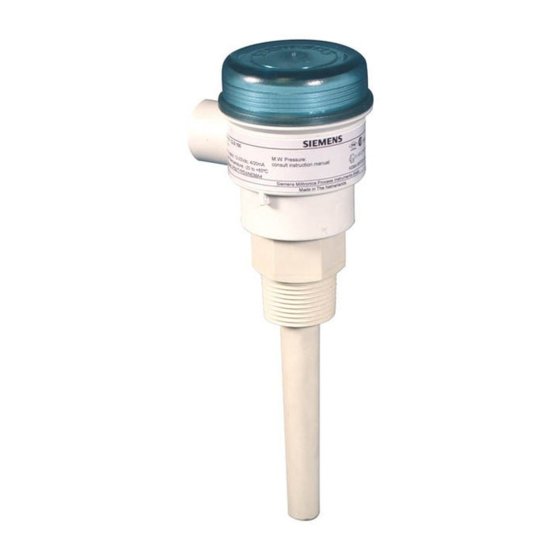
Introduction to the Pointek CLS 100 Note : Pointek CLS 100 is to be used only in the manner outlined in this instruction manual. The Pointek CLS 100 capacitance level switch provides 4 or 20 mA output and solid state switch contact for detection of high and low process material levels. -
Page 5: Specifications
(εr): temperature –40 to 110 °C (–40 to 230 °F) pressure (vessel) 0 absolute to 1000 kPa (10 bar or 146 psi) gauge, nominal ® Kynar is a registered trade mark of ELF Atochem Page 3 Pointek CLS 100 7ML19985AU01.1... - Page 6 Approvals • cable version: • CENELEC • • KEMA • enclosure version: • CENELEC • • KEMA 7ML19985AU01.1 Pointek CLS 100 Page 4...
-
Page 7: Installation
• This product is susceptible to electrostatic shock. Follow proper grounding procedures. The Pointek CLS 100 is normally mounted into the vessel top (high detection alarm) or through the tank wall at the detection level (high or low detection alarm). -
Page 8: Outline And Dimension
Outline and Dimension Cable Version Ground Post 36mm (1.4”) Cable Relief Power LED (green) Output Status LED (red) Sensitivity Trimpot Sensor status LED (yellow) Cable Ø 5mm (0.2”) Trimpot Cap 45mm (1.8”) Process Connection 120mm (4.7”) 7ML19985AU01.1 Pointek CLS 100 Page 6... -
Page 9: Enclosure Version
Enclosure Version 80mm (3.2”) Power LED (green) Cable Entrance Sensitivity Trimpot 65mm (2.6”) Sensor Status LED (yellow) Output Status LED (red) Terminal Block 65mm (2.6”) Process Connection 204mm (8.0”) Page 7 Pointek CLS 100 7ML19985AU01.1... -
Page 10: Mounting
< 50mm (2”) > 100mm (4”) Ø Multiple Units Side View End View 100mm (4”) min 100mm (4”) min 100mm (4”) min Sensors must be 100mm apart. Mount diagonally if vertical space is restricted. 7ML19985AU01.1 Pointek CLS 100 Page 8... - Page 11 Wall Restriction 50mm (2”) min 50mm (2”) min Page 9 Pointek CLS 100 7ML19985AU01.1...
-
Page 12: Process Cautions
Process Cautions Caution: Keep out of path of falling Caution: Consider material surface material. configuration when installing unit. Caution: protect probe from falling material. Caution: avoid areas where material build up occurs. 7ML19985AU01.1 Pointek CLS 100 Page 10... -
Page 13: Connections
Note : The mA current loop can be wired in either polarity to determine high or low level operation as shown in the examples starting on page 13. Page 11 Pointek CLS 100 7ML19985AU01.1... -
Page 14: Alarm Output Status
• Condition in which the material has reached a maximum level for the process (probe covered). Low Alarm • Condition in which the material has reached a minimum level for the process (probe uncovered). 7ML19985AU01.1 Pointek CLS 100 Page 12... -
Page 15: Power / Alarm Wiring
10-33 V dc 4 / 20 mA Loop Alarm Rmax = V supply – 10 V 20 ma For example, 250Ω gives 1 or 5 volt dc switch voltage to PLC. V supply 10–33V dc Page 13 Pointek CLS 100 7ML19985AU01.1... -
Page 16: Solid State Switch Application
Orient the diode based on the current flow. Enclosure Version See pg. 13 for cable equivalents. External Relay Protection Diode (customer Enclosure Version supplied) See pg. 13 for cable equivalents. External Relay Protection Diode (customer supplied) 7ML19985AU01.1 Pointek CLS 100 Page 14... -
Page 17: Connection Diagram - Hazardous Location
Connection Diagram – Hazardous Location Page 15 Pointek CLS 100 7ML19985AU01.1... -
Page 18: Connection Drawing - Non-Hazardous Location
Connection Drawing – Non-Hazardous Location 7ML19985AU01.1 Pointek CLS 100 Page 16... -
Page 19: Operation
This LED indicaties the mA loop alarm and solid state switch contact status. Refer to Alarm Output Status on page 12. Green = power: This LED is on when the Pointek CLS is properly powered. Page 17 Pointek CLS 100 7ML19985AU01.1... -
Page 20: Alarm Output
With sensor uncovered and a minimum 100 mm free space all around, turn the trimpot CW (clockwise) until the yellow LED just goes ON. Turn the trimpot CCW until the yellow LED just goes OFF 7ML19985AU01.1 Pointek CLS 100 Page 18... - Page 21 Immerse the sensor in the material that has the highest dielectric constant; the yellow LED should come ON. Note: After completing the setup, replace the trimpot cap. The unit is now in service, providing level detection of your process. Page 19 Pointek CLS 100 7ML19985AU01.1...
-
Page 22: Troubleshooting
/ Yellow LED doesn’t Possible failed sensor – uncovered. Previous change state as in 2 and 3 check with supplier checks not effective above. Maintenance The Pointek CLS requires no maintenance or cleaning. 7ML19985AU01.1 Pointek CLS 100 Page 20... -
Page 23: Appendix: Approvals
Appendix: Approvals WRITTEN DECLARATION OF CONFORMITY We, , , , Siemens Milltronics Process Instruments B.V. Nikkelstraat 10 - 4823 AB BREDA - The Netherlands Declare, solely under own responsibility, that the product Pointek CLS 100 Point Level Switch, Mentioned in this declaration, complies with the following... -
Page 24: Index
Trim Pot Placement ..........20 High Alarm............14 Troubleshooting........... 22 Horizontal..............7 Vertical ..............7 Indicators ..............19 inductive spikes ...........16 Installation Features and Restrictions ....10 Introduction ............4 Wall Restriction ........... 11 Label Colors............9 7ML19985AU01.1 Pointek CLS 100 Page 22... - Page 25 ©...
Need help?
Do you have a question about the POINTEK CLS 100 and is the answer not in the manual?
Questions and answers