Table of Contents
Advertisement
Quick Links
Advertisement
Table of Contents

Related Manuals for Siemens Sicharge CC AC22-ERK


Summary of Contents for Siemens Sicharge CC AC22-ERK
- Page 2 SICHARGE Operating instructions, ERK Introduction Safety instructions SICHARGE Description Assembly/installation SICHARGE CC AC22 - ERK SICHARGE Operating instructions, Connecting and commissioning Operation Operating Instructions Malfunctions Maintenance and service Adhesive surfaces Service & Support Disposal Technical specifications Appendix List of abbreviations 06/2021 A5E48571690-AC...
- Page 3 Note the following: WARNING Siemens products may only be used for the applications described in the catalog and in the relevant technical documentation. If products and components from other manufacturers are used, these must be recommended or approved by Siemens. Proper transport, storage, installation, assembly, commissioning, operation and maintenance are required to ensure that the products operate safely and without any problems.
-
Page 4: Table Of Contents
Table of contents Introduction ............................6 Purpose of this documentation .................... 6 Conventions ........................6 Open-source software ......................7 Safety instructions ..........................8 General safety information ....................8 Safe installation and assembly ................... 11 Safety during electrical installation ..................13 Safety during operation ..................... - Page 5 Software updates......................103 Adhesive surfaces ..........................104 Adhesive surfaces ......................104 Service & Support ..........................106 10.1 Siemens Industry Support ....................106 Disposal ............................. 107 Technical specifications ........................108 Appendix ............................111 Overview of article numbers .................... 111 Spare parts ........................113 Installation and maintenance schedule ................
- Page 6 Table of contents A.10 Transparency software ..................... 132 A.10.1 Retrieving measured values ..................... 132 A.10.2 Installation and operation ....................140 A.10.3 Implementation ....................... 145 A.11 Quality documentation ....................150 List of abbreviations .......................... 151 SICHARGE Operating instructions, ERK Operating Instructions, 06/2021, A5E48571690-AC...
-
Page 7: Introduction
Introduction Purpose of this documentation These operating instructions contain the information required for installing, commissioning, and operating the SICHARGE CC AC22 charging station. The operating instructions contain information on proper use of the charging station. WARNING Failure to comply with the information in these operating instructions may result in the following: •... -
Page 8: Open-Source Software
Siemens accepts no liability for the use of the open-source software over and above the intended program sequence, or for any faults caused by modifications to the software. -
Page 9: Safety Instructions
Safety instructions General safety information This section contains important, generally valid information on: • Preventing accidents and material damage • Application planning • Mounting and installation • Operation • Maintaining and cleaning the charging station Read this section carefully and follow the safety regulations. This will minimize safety risks. Make your staff and customers aware of this section. - Page 10 Safety instructions 2.1 General safety information Target group The sequence of the following safety instructions is based on the use stages of the product life cycle. The description is addressed to the following groups of people: • The operator responsible for the safe operation of the device •...
- Page 11 Safety instructions 2.1 General safety information Qualified personnel All activities should be performed by qualified personnel. Due to their education, experience and training, such people have knowledge of: • Relevant standards and regulations • Accident prevention guidelines They are authorized to perform the necessary activities and to detect and prevent possible dangers.
-
Page 12: Safe Installation And Assembly
Safety instructions 2.2 Safe installation and assembly Cleaning Protect the environment and use biodegradable cleaning agents to clean the surfaces. Clean the surfaces of the charging station with a damp cloth. Do not use a steam or water jet for cleaning, because moisture or water may penetrate into the charging station. - Page 13 Safety instructions 2.2 Safe installation and assembly Electrical cables There is a risk of electric shock due to exposed electrical connections and components. Before starting the installation work, check that the supply cable has been disconnected from the mains and secured against restart. If damage or tampering is visible, do not commission the charging station.
-
Page 14: Safety During Electrical Installation
Safety instructions 2.3 Safety during electrical installation Safety during electrical installation Observe the following points for the electrical installation. The electrical connection of the charging station can only be performed by skilled electricians and can only be carried out at zero current. - Page 15 Safety instructions 2.3 Safety during electrical installation Damage to sockets and charging cable Inspect sockets and the charging cable for damage on a regular basis. Damaged charging cables endanger safe operation. If you detect damage to the charging cable, do not commission the cable or stop a running charging process.
-
Page 16: Safety During Operation
Safety instructions 2.4 Safety during operation Safety during operation Observe the following points when operating the charging station, as well as the applicable regional standards and regulations. Failure to follow safety instructions may result in hazardous situations that could cause death or serious injury. Safety at the work site When working on roads, construction sites and in public areas, ensure safety in line with local requirements and regulations. -
Page 17: Safe Cleaning And Maintenance
Safety instructions 2.5 Safe cleaning and maintenance Safe cleaning and maintenance Observe the following points for cleaning and maintenance. Electrical equipment may only by cleaned and maintained by qualified personnel. Act according to the safety instructions given. Observe the applicable regional standards and regulations. Failure to follow safety instructions may result in hazardous situations that could cause death or serious injury. -
Page 18: Security Information
In order to protect plants, systems, machines, and networks against cyber threats, it is necessary to implement – and continuously maintain – a holistic, state-of-the-art industrial security concept. Siemens’ products and solutions constitute one element of such a concept. Operators of the charging station are responsible for preventing unauthorized access to their plants, systems, machines, and networks. -
Page 19: Safety-Relevant Symbols
Safety instructions 2.7 Safety-relevant symbols Safety-relevant symbols Icons for SICHARGE CC AC22 The following table explains icons than may be located on your product, on its packaging, or in the accompanying documentation. Symbol Meaning General warning sign Caution/Notice You must read the product documentation. The product documentation contains information about the type of potential hazard and helps to recognize risks and implement countermeasures. -
Page 20: Identification Of The Device Erk
Safety instructions 2.8 Identification of the device ERK Identification of the device ERK Two identical nameplates are located on the rear of the charging station and on the inside of the device door. The nameplates provide information about the device name, serial number and important connection information. -
Page 21: Description
Description Application This charging station is a first-class, cutting edge product. You can charge electrically powered vehicles safely and reliably with the SICHARGE CC AC22 charging station. Charging stations can be used for stand-alone operation. They can also be integrated into flexible, modular, and retrofittable infrastructure. -
Page 22: Charging Station Structure
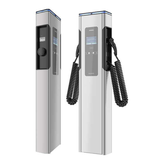
Description 3.2 Charging station structure Charging station structure ① Status light ⑤ Pushbutton ② RFID reader ⑥ Maintenance door ③ Viewing window for meter ⑦ Option: Fixed charging cable ④ Charging connection type 2 Figure 3-1 Charging station structure SICHARGE Operating instructions, ERK Operating Instructions, 06/2021, A5E48571690-AC... -
Page 23: Charging Module Structure
Description 3.3 Charging module structure Charging module structure Options and accessories may vary. SICHARGE Operating instructions, ERK Operating Instructions, 06/2021, A5E48571690-AC... - Page 24 Description 3.3 Charging module structure ① Multiple door lock ⑩ Contactor for charging point ② Status light for each charging point ⑪ Power supply unit ③ Control cabinet fan ⑫ Charging controller fuse ④ Charging controller ⑬ PE terminal ⑤ Viewing window for meter ⑭...
-
Page 25: Design Of Charging Module With Fixed Charging Cable Option
Description 3.4 Design of charging module with fixed charging cable option Design of charging module with fixed charging cable option Options and accessories may vary. SICHARGE Operating instructions, ERK Operating Instructions, 06/2021, A5E48571690-AC... -
Page 26: Flowchart
Description 3.5 Flowchart ① Multiple door lock ⑩ Contactor for charging point ② Status light for each charging point ⑪ Power supply unit ③ Control cabinet fan ⑫ Charging controller fuse ④ Charging controller ⑬ PE terminal ⑤ Viewing window for meter ⑭... -
Page 27: Charging Controller
Description 3.6 Charging controller Charging controller ① Charging point 1, electronic residential meter connection ② Charging point 1 charging module controller (MCB, RCCB, contactor, charging socket type 2, status indicator) ③ 4G module or Ethernet module ④ Charging point 2, electronic residential meter connection ⑤... - Page 28 The SIM card is required for communication e.g. with the backend. The SIM card is not included in the standard delivery of the charging station. If desired, an optional pre-configuration can be carried out at the manufacturer. Contact Siemens branch for more information.
- Page 29 Description 3.6 Charging controller SD card seal The security seal of the SD card is used as access protection/manufacturer protection. The seal of the SD card is a manufacturer seal. If the security seal of the SD card under the cover is broken, shut down the unit and inform the manufacturer.
-
Page 30: Covers For Infeed And Charging Modules
Description 3.7 Covers for infeed and charging modules User seal for plug-in connections of the charging point controller The operator is obligated to attach a user seal to the two plug-in connections of the charging point controller. The two plug-in connections are labeled in the graphic above "Description of the charging controller"... - Page 31 Description 3.7 Covers for infeed and charging modules ① Sealing of the charging modules by operators ② Cover for charging modules ③ Sealing of the infeed area by the operator ④ Feed cover SICHARGE Operating instructions, ERK Operating Instructions, 06/2021, A5E48571690-AC...
-
Page 32: Counter Seal
Description 3.8 Counter seal Counter seal The seal of the counter serves as access / manufacturer protection. The seal protects counters against tampering or removal. The manufacturer seals the counter using a seal. Only personnel authorized by the manufacturer may open the seals. If you find a damaged seal, take the device out of service and report it immediately to the operator and manufacturer. -
Page 33: Assembly/Installation
Assembly/installation Safety measures during assembly General information Charging of electric cars must guarantee high performance over long periods. The installation and pre-installation of the charging station must comply with the power requirements. To ensure that these requirements are fulfilled correctly, these installation instructions are intended for qualified and trained electricians. -
Page 34: Preparation Before Assembly
• Prepare and position the concrete foundation according to the "foundation and reinforcement plan" of the respective installation type. – Foundation and reinforcement plan for standard version (https://support.industry.siemens.com/cs/ww/de/view/109780588) – Foundation and reinforcement plan for option: HAK (https://support.industry.siemens.com/cs/ww/de/view/109780588) • Anchor the four segment anchor rods or the mounting plate in the concrete foundation according to the "Foundation and reinforcement plan"... - Page 35 Assembly/installation 4.2 Preparation before assembly Required tools The required tools are not included in the scope of delivery. • Combination wrench set up to 19 width across flats • Key for housing (in the accessory kit) • Spirit level • Phillips head screwdriver set •...
-
Page 36: Assembly Procedure
Assembly/installation 4.3 Assembly procedure Assembly procedure Specific safety measures DANGER Risk of electric shock when moist due to condensed water Before commissioning the charging station, an authorized and qualified electrician must check whether there is moisture in the charging station. Remove even small amounts of condensed water before commissioning. - Page 37 Assembly/installation 4.3 Assembly procedure WARNING Risk of accident Risk of accident in limited space. Leave sufficient clearance to surrounding obstacles to avoid collisions and crushing when setting up the charging station. • Ensure that there is sufficient clearance to the surrounding obstacles when setting the load down.
- Page 38 Assembly/installation 4.3 Assembly procedure Preparing the foundation Check that the foundation is horizontal using a spirit level. ① Cable entry, view from the bottom Figure 4-1 Foundation, base view Figure 4-2 Top view of the foundation SICHARGE Operating instructions, ERK Operating Instructions, 06/2021, A5E48571690-AC...
- Page 39 HAK option With the HAK option, the foundation and cable routing are different than shown in this figure. The foundation and reinforcement plan can be found here (https://support.industry.siemens.com/cs/ww/de/view/109780588). Note Ethernet interface version For the version with Ethernet interface, you require an additional empty tube or corrugated tube for the network cable.
- Page 40 Assembly/installation 4.3 Assembly procedure Opening the housing WARNING Crushing hazard The weight of the standard version is 75 kg. Depending on the options ordered, the weight differs from the standard version. Lifting the unit may result in hazards that could cause not only serious material damage but also serious injury.
- Page 41 Assembly/installation 4.3 Assembly procedure The keys for the unit and the control cabinet are on the right. To open the housing, follow these steps: 1. Turn the unit key to the right. Hold the key in this position. 2. To unlock the door, turn the switch cabinet key to the right. Mounting the charging station onto the concrete foundation 1.
- Page 42 Assembly/installation 4.3 Assembly procedure 10.Mount the sealing plate flush with the mounting plate. Figure 4-4 Cable entry SICHARGE Operating instructions, ERK Operating Instructions, 06/2021, A5E48571690-AC...
- Page 43 Assembly/installation 4.3 Assembly procedure 11.Fill the charging station with base filler up to the black line (e.g. Hager ZAY95075). Figure 4-5 Marking for base filler Sticker with the quick reference guide for charging The charging station is supplied with a sheet of stickers. The stickers describe the procedure for starting and ending the charging.
- Page 44 Assembly/installation 4.3 Assembly procedure Figure 4-6 Position of the sticker SICHARGE Operating instructions, ERK Operating Instructions, 06/2021, A5E48571690-AC...
-
Page 45: Connecting And Commissioning
Connecting and commissioning Connecting the supply cable Select the cable cross-section according to load and voltage drop: Note Three-phase operation The charging station may only be operated with 3 phases + N + PE. The specifications can be obtained from the rating plate (Page 19). •... - Page 46 Connecting and commissioning 5.1 Connecting the supply cable To connect the supply cable, proceed as follows: 1. Sheath the power supply cable above the strain relief. Make the protective conductor at least 50 mm longer than L and N. 2. Lay the cables in the housing in loops, as shown in the following figure. Figure 5-1 Infeed unit Note...
- Page 47 The electrical circuit diagram is located in the maintenance door in the document compartment of the SICHARGE charging station. The electrical circuit diagram can be downloaded here (https://support.industry.siemens.com/cs/ww/de/view/109780588). See also Options available for orders (Page 116) SICHARGE Operating instructions, ERK...
-
Page 48: Optional Equipment
Connecting and commissioning 5.2 Optional equipment Optional equipment Optional equipment ① Last Gasp ② Ethernet interface ③ Overvoltage protection or lightning protection ④ Double terminal Figure 5-2 Order options Last Gasp The Last Gasp function is an option that can be ordered additionally. This option includes an internal add-on module that does the following in the event of a power failure: •... - Page 49 A conversion kit is available for converting systems with a 4G module. To do this, follow the instructions in the Repair instructions (https://support.industry.siemens.com/cs/ww/en/view/109793281). Section Spare parts (Page 113) includes the article number of the conversion kit. You can find the overview of the various article numbers in the section Overview of article numbers (Page 111).
-
Page 50: Sim Card
Connecting and commissioning 5.3 SIM card Lightning protection If you have ordered the lightning protection option, an additional internal module is installed. This module is a 4-pin combination arrester with a remote signaling contact. The combination arrester limits the follow-on current and dissipates the lightning energy via dedicated grounding. - Page 51 Connecting and commissioning 5.3 SIM card Insert/remove SIM card Follow the instructions below to insert or remove the SIM card: 1. Remove the two screws from the card cover of the charging controller ① Card cover 2. Remove the card cover from the charging controller 3.
-
Page 52: Switching On And Testing
Connecting and commissioning 5.4 Switching on and testing Switching on and testing Procedure for switching on and checking the charging station. Perform the following steps to switch on the charging station. 1. Switch the power supply on. Switch on the backup fuses, the load breaker switch and the RCCB. 2. - Page 53 Connecting and commissioning 5.5 Commissioning Change Password We recommend changing the password during commissioning. Comply with current rules of applicable IT standards for creating and managing secure passwords. NOTICE Manage password Manage the new password carefully. The password cannot be reset or retrieved on site. The password can be reset via the backend.
- Page 54 Connecting and commissioning 5.5 Commissioning Dashboard The status of the connections is shown in tab "Dashboard". Figure 5-4 Dashboard SICHARGE Operating instructions, ERK Operating Instructions, 06/2021, A5E48571690-AC...
- Page 55 Connecting and commissioning 5.5 Commissioning Network/Interfaces Set the network connection in the "Network/Interfaces" tab. Set the check mark at "Use DHCP" to reach the charging station with a name. Remove the check mark to enter the network settings. For remote maintenance and updates, you must set the check mark for "Enable VPN" and enter the port setting.
- Page 56 SIM card The SIM card must be operated in a closed APN. Otherwise, SICHARGE AC22 is vulnerable and a sustainable connection cannot be guaranteed. Should you have any questions, contact the relevant Siemens branch. Figure 5-6 Network Mobile SICHARGE Operating instructions, ERK...
- Page 57 Connecting and commissioning 5.5 Commissioning Network/Proxy Set the proxy connection in the "Network/Proxy" tab. Set the check mark at "Use Proxy" to install the system behind a proxy server. Now, enter the proxy data in these fields. Enter proxy credentials in the "User" and "Password" fields. Figure 5-7 Network Proxy SICHARGE Operating instructions, ERK...
- Page 58 You do not need to change anything in the "Chargebox ID (Template)" field. If the backend requests the Chargebox ID, enter this separately in the "Chargebox ID (Template)" field. Enter the authorization key provided by the backend in the "Authorization Key" field. Figure 5-8 OCPP Siemens SICHARGE Operating instructions, ERK Operating Instructions, 06/2021, A5E48571690-AC...
- Page 59 Connecting and commissioning 5.5 Commissioning Figure 5-9 OCPP custom SICHARGE Operating instructions, ERK Operating Instructions, 06/2021, A5E48571690-AC...
- Page 60 Connecting and commissioning 5.5 Commissioning Station/Date/Time Set the time zone and the synchronization in the "Station/Date/Time" tab. If you check the "Timezone" box, the time zone of your browser is automatically applied. Clear the check box to select the time zone in the drop-down menu. In the area of "Synchronize date and time via", set the check mark for "NTP"...
- Page 61 Connecting and commissioning 5.5 Commissioning Station/components Carry out a firmware update in the "Station/components" tab. NOTICE Overwriting firmware Ensure that the charging processes have been completed properly before overwriting the firmware. Figure 5-11 Station Components SICHARGE Operating instructions, ERK Operating Instructions, 06/2021, A5E48571690-AC...
- Page 62 Connecting and commissioning 5.5 Commissioning Station/Connectors The tab "Station/Connectors" has the following items: Points Status Meaning EVSE ✓ Electric Vehicle Supply Equipment ✓ Identification of the charging point Type ✓ Charging point type Hardware ID ✓ Hardware identification number Firmware ✓...
- Page 63 Connecting and commissioning 5.5 Commissioning Figure 5-12 Station Connectors1 SICHARGE Operating instructions, ERK Operating Instructions, 06/2021, A5E48571690-AC...
- Page 64 Connecting and commissioning 5.5 Commissioning Figure 5-13 Station Connectors2 SICHARGE Operating instructions, ERK Operating Instructions, 06/2021, A5E48571690-AC...
- Page 65 Connecting and commissioning 5.5 Commissioning Station/Power WARNING Entering the maximum current for each outer conductor Only a qualified electrician can make an entry in this field. Enter the maximum available current for each phase in mA for the charging station. The value must not exceed the rated current of the back-up fuse.
- Page 66 Connecting and commissioning 5.5 Commissioning GUI/Branding Set the HMI displays in the "GUI/Branding" tab. Figure 5-15 GUI Branding SICHARGE Operating instructions, ERK Operating Instructions, 06/2021, A5E48571690-AC...
- Page 67 Connecting and commissioning 5.5 Commissioning Language Select the language of the HMI display in the "Language" tab. Figure 5-16 GUI Language SICHARGE Operating instructions, ERK Operating Instructions, 06/2021, A5E48571690-AC...
- Page 68 Connecting and commissioning 5.5 Commissioning Advertisement Set up HMI advertising in the "Advertisement" tab. Select the provider if it does not correspond to the backend. Enter the URL, user and password for the advertisement. Set the update interval for the advertising file in "Data Synchronization". Set the time until advertising begins in "Display Timeout".
- Page 69 Connecting and commissioning 5.5 Commissioning Authentication Set the authentication in the "User Managment/Authentication" tab. Selection Meaning ? any RFID If recognized, use any RFID. x no RFID Do not use RFID in any check. ✓ a white- Use the whitelist when checking the RFID. listed RFID Figure 5-18 User Management Authentication...
- Page 70 Connecting and commissioning 5.5 Commissioning Users (RFID Cards) Tab "User Managment/Users (RFID Cards)" provides an overview of customers. In this tab, you can change the status of the customer. Click on the respective icon to change the status of a customer between active / inactive and valid / invalid.
- Page 71 Connecting and commissioning 5.5 Commissioning Software The "Software" tab displays the currently installed software of the charging station. Figure 5-20 Software Concluding commissioning 1. Disconnect the Ethernet cable from the charging station. 2. Seal the cover plates. 3. Lock the housing door with the key. 4.
-
Page 72: Operation
Operation Status indicators Notes on operation The SICHARGE CC AC22 charging station is equipped with status indicators. Different colors and flashing signals indicate the current status of charging points 1 and 2. This signalizes to drivers if the charging station is available and what its status is. The display also directly shows the required information. - Page 73 Operation 6.1 Status indicators Status indicators The following table provides an overview of status indicators of charging points: Does not light up If the status indicator does not light up, this indicates an interruption to the power supply. If there is not a power failure, check the backup fuses.
-
Page 74: Main Menu
Operation 6.2 Main menu Main menu Symbols in the main menu When you switch on the charging station, you will see the following picture on the display. ① Charging station and connection status ② Display of instructions ③ Charging point indicator Figure 6-2 Main menu SICHARGE Operating instructions, ERK... - Page 75 Operation 6.2 Main menu Table 6- 1 Symbols of the charging station and connection status Hardware fault Charging point status Charging station reserved Mobile network reception, network strength Mobile reception, data connection (GSM, 2G, 3G, LTE) Connection to the OCPP backend RFID card reader SIM card (controller) Micro SD card...
- Page 76 Operation 6.2 Main menu Table 6- 2 Symbols of the charging point indicators Charging point number Active meter (value/status) Identification (meter) Vehicle status Plug status Charge point cover Charging status Circuit breaker status Meter status Available power Query to the meter The symbols are explained in the help menu.
-
Page 77: Charging Process
Operation 6.3 Charging process Charging process 6.3.1 Start charging Safety instructions during the charging process DANGER Risk of electric shock and fire Touching live parts may cause electric shock or even death! Defective connectors or cables may cause fire. • Do not kink or squeeze the charging cable. Do not draw the charging cable over sharp edges or hot surfaces. - Page 78 Operation 6.3 Charging process Start charging with RFID or app Proceed as follows to start charging: 1. Check if the required charging point is ready for operation: The status LED must light up green. 2. You will see the following instruction on the display: "Press the button below the display and follow the instructions".
- Page 79 Operation 6.3 Charging process Start charging with Giro-e function Requirement: The Giro-e function is enabled on the device. (Configuration via web interface or backend) Additional information about Giro-e is available here (Page 128). Proceed as follows to start charging: 1. Check if the required charging point is ready for operation: The status LED must light up green.
-
Page 80: Completing The Charging Process
Operation 6.3 Charging process The status LED pulsating in blue indicates that current is flowing to the vehicle and the vehicle battery is charging. The status LED lights up permanently in blue in the following cases: • The vehicle is not drawing current. –... - Page 81 Operation 6.3 Charging process Completing the charging process Your vehicle is being charged as long as the light pulsates in blue. Charging is complete when the light of the status indicator is constant. You can stop charging at any time. You have three different options to end charging: Procedure with RFID card or debit card 1.
-
Page 82: Malfunctions
Malfunctions Fault elimination DANGER Risk of electric shock and fire Touching live parts may cause electric shock or even death! Damaged charging cables and connectors can cause a fire. • The system may only be opened and repaired by the manufacturer, its service department or similarly qualified persons. -
Page 83: Rfid Fault
Malfunctions 7.2 Service technician faults 7.2.2 RFID fault RFID fault message If there is a fault on the RFID reader, the following message is shown on the display. Description Cause Solution RFID card not recognized RFID reader not (properly) connected. Check whether the RFID reader is correctly con- nected to the RFID board (VEN_ADA0). -
Page 84: Ocpp Messages
Malfunctions 7.2 Service technician faults 7.2.4 OCPP messages Message display The messages displayed on the server (e.g. web interface) may differ from the display messages. This is due to the server setting. Ask the backend provider how to correctly assign the OCPP specified messages/types. Status messages to the backend The various status messages are listed in the following table. - Page 85 Malfunctions 7.2 Service technician faults RFID reader Message frame text Charging station ⇒ Backend: ReaderFailure Message frame text Backend ⇒ Charging station: Available Component: Charging station Status LED: No effect Description Cause Solution No RFID reader found RFID reader not plugged in Check wiring/connection to the RFID reader.
- Page 86 Malfunctions 7.2 Service technician faults Fault: EV connection error Message frame text Charging station ⇒ Backend: EVCommunicationError Message frame text Backend ⇒ Charging station: Faulted Component: Charge point 1 or 2 Status LED: Flashes red 1x Description Cause Solution Connection error to the vehicle Communication with the EV-controller Check wiring/connection to the vehicle.
- Page 87 Malfunctions 7.2 Service technician faults Circuit breaker fault Message frame text Charging station ⇒ Backend: OverCurrentFailure Message frame text Backend ⇒ Charging station: Faulted Component: Charge point 1 or 2 Status LED: Flashes red 3x Description Cause Solution The main contactor gets stuck. The Replace the main contactor.
- Page 88 Malfunctions 7.2 Service technician faults Meter fault Message frame text Charging station ⇒ Backend: PowerMeterFailure Message frame text Backend ⇒ Charging station: Faulted Component: Charge point 1 or 2 Status LED: Flashes red 6x Description Cause Solution Meter error The meter is incorrectly wired. Check the wiring.
-
Page 89: Faqs
Malfunctions 7.3 FAQs SD card fault Message frame text Charging station ⇒ Backend: OtherError (RegulatoryComplianceFailure) Message frame text Backend ⇒ Charging station: Faulted Component: Charge point 1 or 2 Status LED: Flashes red 10× Description Cause Solution SD card faulty SD card defective Replace SD card Note:... - Page 90 Malfunctions 7.3 FAQs Symbol Meaning Solution Communication error (Mode 3) Disconnect the vehicle from the charging station and reconnect the vehicle. Check the vehicle. Check the charging cable. Check the charging station (plug and cable). Vehicle not connected Connect the charging cable to the vehicle and to the charging station.
- Page 91 Malfunctions 7.3 FAQs Symbol Meaning Solution Phase/line not available. Check whether the voltage on all lines L1 ... L3 is between 207 ... 255 V. 100% of the max. power (22 kW) is available 75% or less of the max. power (22 kW) is available 50% or less of the max.
- Page 92 Malfunctions 7.3 FAQs Symbol Meaning Solution Charging station inactive (inten- Activate again (via OCPP backend server) tionally deactivated) Hardware fault Request service for repair. The charging station is not con- Check the network connection and the nected to the OCPP server. router setting.
- Page 93 Malfunctions 7.3 FAQs Symbol Meaning Solution -15 – -25 °C < -25 °C Charging is not possible SICHARGE Operating instructions, ERK Operating Instructions, 06/2021, A5E48571690-AC...
-
Page 94: Maintenance And Service
Maintenance and service Cleaning and maintenance Safety measures Note Before cleaning or service work, disconnect the system from the power and ensure it cannot be switched back on. To do this, deactivate at least all fuses to which the charging station is connected. -
Page 95: Maintenance
Maintenance and service 8.2 Maintenance Cleaning guidelines • Do not use solvents or corrosive or abrasive detergents. • Use a mild, non-corrosive cleaning agent, e.g. dishwashing detergent, even if heavily soiled. • Wipe the charging station from the outside with a moist cloth and rub the station dry. •... - Page 96 Maintenance and service 8.2 Maintenance Inspecting safety devices The charging station has at least one integrated residual current circuit breaker (RCCB) and miniature circuit breaker (MCB). Check all protective devices during commissioning in accordance with the national installation regulations. You can only check the RCCB/MCB combination when the supply voltage is present.
- Page 97 Maintenance and service 8.2 Maintenance Maintenance of fans and filter mats In the course of checking the safety equipment, check the function of the fans twice yearly and replace the filter mats on a preventive basis. Pollution may be lighter or heavier depending on the place of installation. Adapt the inspection and replacement interval of the filter mats to the place of installation.
-
Page 98: Diagnostic Tests
Secure the charging station against being switched on again. Only personnel authorized by the operator may break seals of the infeed cover and charging module covers during testing. Only personnel authorized by Siemens may: • Break seals of the meter • Break seals of the SD card •... - Page 99 Maintenance and service 8.3 Diagnostic tests Remove the meter Follow these steps to remove the meter. Check that the charging station is de-energized. 1. Remove the screws from the meter cover plate. 2. Remove the screws from the meter support plate. Figure 8-2 Mounting the meter 3.
- Page 100 Maintenance and service 8.3 Diagnostic tests 4. Turn the meter to the center position. Figure 8-3 Meter charging point left Figure 8-4 Meter charging point right SICHARGE Operating instructions, ERK Operating Instructions, 06/2021, A5E48571690-AC...
- Page 101 Maintenance and service 8.3 Diagnostic tests 5. Remove the seal on the sealing pin. Figure 8-5 Meter seal SICHARGE Operating instructions, ERK Operating Instructions, 06/2021, A5E48571690-AC...
- Page 102 Maintenance and service 8.3 Diagnostic tests 6. Use a screwdriver to unscrew the sealing pin. The sliding lock opens. Figure 8-6 Meter sealing pin 7. Push the meter out of the adapter plate by lightly pressing upwards. Figure 8-7 Remove the meter SICHARGE Operating instructions, ERK Operating Instructions, 06/2021, A5E48571690-AC...
- Page 103 Open and check the data using the Transparenz software. If you remove the SD card, the charging station is not available until you insert the card again. Note SD card type Only use an SD card that is approved by Siemens. SICHARGE Operating instructions, ERK Operating Instructions, 06/2021, A5E48571690-AC...
-
Page 104: Software Updates
8.4 Software updates Software updates Software updates Siemens makes software updates available as part of ongoing feature enhancements and improvements. Check the software version of your system (Page 70) regularly. Keep the software version of your system up-to-date with software updates. -
Page 105: Adhesive Surfaces
Adhesive surfaces Adhesive surfaces Marking of adhesive surfaces The hatched areas of the following drawings must not be covered with glue, paint or covered. The supplied quick reference guide is an exception. The quick reference guide is affixed underneath the meter inspection window. Ventilation slots and the maintenance door must not be restricted or obstructed. - Page 106 Adhesive surfaces 9.1 Adhesive surfaces Note Option: Full or partial foiling As an option, you can order foiling including adhesive from the factory. SICHARGE Operating instructions, ERK Operating Instructions, 06/2021, A5E48571690-AC...
-
Page 107: Service & Support
• Forums For answers and solutions in all matters of automation technology. • mySupport Your personal working area in Siemens Industry Online Support for notifications, support queries, and configurable documents. This information is provided by Siemens Industry Online Support (https://support.industry.siemens.com/cs/ww/)on the internet. -
Page 108: Disposal
Disposal Disposing of packaging The packaging of the SICHARGE AC22 contains no hazardous substances. Send the packaging for recycling in accordance with the applicable regulations in your country. Disposing of the battery Do not dispose of batteries with household waste. Follow local, national, and international regulations to dispose of the battery. -
Page 109: Technical Specifications
Technical specifications Performance features and options Designation SICHARGE CC AC22 ● Standard, O available as an option Charge points type 2, 32 A acc. to IEC 62196-1,2 and 61851-1 Connector lock type 2 ● Flap lock type 2 ● Charge current can be set from 6 ... 32 A ●... - Page 110 Technical specifications Technical specifications Designation SICHARGE CC AC22 Display 7" LED Supply voltage AC 400 V ± 10 % 3-phase N+PE Connection frequency 50 Hz Maximum connected power 63 A / phase Maximum charging capacity per charging point 22 kW Load management acc.
- Page 111 Technical specifications Storage and transport Follow the following framework conditions when storing and transporting the charging station: • The permissible storage temperature of the charging station is -25 to +50 °C. • The permissible air humidity is 5 to 95%, non-condensing. •...
-
Page 112: Appendix
Appendix Overview of article numbers Overview of the article number structure The following graphic shows the article number structure. SICHARGE Operating instructions, ERK Operating Instructions, 06/2021, A5E48571690-AC... - Page 113 Appendix A.1 Overview of article numbers Figure A-1 Overview of article number structure SICHARGE Operating instructions, ERK Operating Instructions, 06/2021, A5E48571690-AC...
-
Page 114: Spare Parts
Appendix A.2 Spare parts Spare parts Spare parts The spare parts listed are available for the charging station. Spare part Article number Weight in kg Calibration law-relevant Display unit SICHARGE FZI:40094.013 Charging socket type 2 SV+KDV FZI:40094.014 Earthed charging socket 16A 230V, type E FZI:40094.015 SICHARGE inspection window FZI:40094.016... -
Page 115: Installation And Maintenance Schedule
Appendix A.3 Installation and maintenance schedule Installation and maintenance schedule SICHARGE AC22 Checklist The following table shows the tasks and their expected duration for the following applications: • Installation/assembly • Commissioning • Maintenance Table A- 1 Installation and maintenance schedule Action Installa- Commis-... - Page 116 Appendix A.3 Installation and maintenance schedule Action Installa- Commis- Mainte- Duration tion/asse sioning nance in min. mbly Check axial fan for: • Function • Running noise • Cleaning Once the charging station has been switched on, the fans run for 15 minutes (test mode) Change air filters on the bottom of the charging station Check the RCCB (semi-annual DGUV V3) including protocol...
-
Page 117: Options Available For Orders
Appendix A.4 Options available for orders Options available for orders Option overview These extensions can be optionally ordered for the SICHARGE CC AC22 . Options and accessories Description Building terminal box to Add-on module for the back of the SICHARGE CC AC22. Allows power SICHARGE CC AC22 connection directly from the utility company. -
Page 118: Option: Hak
Appendix A.5 Option: HAK Option: HAK HAK building junction box The HAK building junction box shown in the illustration is available in the following versions. Table A- 2 HAK versions HAK housing, empty HAK with meter cabinet and building junction The HAK housing is available in various models for the installation of a building junction box and a meter cabinet. - Page 119 Appendix A.5 Option: HAK The following figure shows the positions for seals. These seals are to be attached by the operator. ① User seal on the top cover ② User seal at ERM for BKE adapter or at the terminal cover for three-point meter ③...
- Page 120 Appendix A.5 Option: HAK HAK housing, empty The following is set up when ordering a HAK housing without equipment. • Mounting points for meter cabinet and building junction box • Connection cable between the HAK and the charging station HAK housing with meter cabinet and building junction box The following is set up when ordering a HAK housing with a meter cabinet and a building junction box.
-
Page 121: Option: Fixed Charging Cable
Appendix A.6 Option: Fixed charging cable 6. Connect the connecting cable of the SICHARGE charging station in the meter cabinet of the HAK housing. 7. After completing the work, the operator must seal all covers in the HAK and the charging station. - Page 122 Appendix A.6 Option: Fixed charging cable The fixed charging cables type 2 are stowed in the brackets on the side of the charging station. With the fixed charging cables type 2, the customer does not need their own charging cable. Follow safety instructions in sections Safety during operation (Page 15) and Charging process (Page 76).
-
Page 123: Overview Of Dimensions Of The Sicharge Cc Ac22 Charging Station
Appendix A.7 Overview of dimensions of the SICHARGE CC AC22 charging station Overview of dimensions of the SICHARGE CC AC22 charging station Dimension drawing of charging station Figure A-4 Dimension drawing of charging station SICHARGE Operating instructions, ERK Operating Instructions, 06/2021, A5E48571690-AC... - Page 124 Dimension drawing of charging station with HAK Figure A-5 Dimension drawing of charging station with HAK Foundation and reinforcement plan The foundation and reinforcement plan for the respective version can be found here (https://support.industry.siemens.com/cs/ww/de/view/109780588). SICHARGE Operating instructions, ERK Operating Instructions, 06/2021, A5E48571690-AC...
-
Page 125: Information On Weights And Measures Regulations
Appendix A.8 Information on weights and measures regulations Information on weights and measures regulations Eichrechtliche Hinweise und Verwenderauflage WICHTIGE HINWEISE FÜR DEN BETREIBER DER LADESTATION Am 17. März 2016 trat die Verordnung über technische Mindestanforderungen an den sicheren und interoperablen Aufbau und Betrieb von öffentlich zugänglichen Ladepunkten für Elektromobile (Ladesäulenverordnung - LSV) in Kraft. - Page 126 Appendix A.8 Information on weights and measures regulations 4. Der Verwender dieses Produkts hat sicherzustellen, dass Ladeeinrichtungen zeitnah außer Betrieb genommen werden, wenn wegen Stör- oder Fehleranzeigen im Display der eichrechtlich relevanten Mensch-Maschine-Schnittstelle ein eichrechtkonformer Betrieb nicht mehr möglich ist. Es ist der Katalog der Stör- und Fehlermeldungen in dieser Betriebsanleitung zu beachten.
- Page 127 Appendix A.8 Information on weights and measures regulations Für den Verwender der Messwerte entstehen aus dieser Regelung konkret folgende Pflichten einer eichrechtkonformen Messwertverwendung: 1. Der Vertrag zwischen EMSP und Kunden muss unmissverständlich regeln, dass ausschließlich die Lieferung elektrischer Energie und nicht die Ladeservice-Dauer Gegenstand des Vertrages ist.
- Page 128 Appendix A.8 Information on weights and measures regulations 10.Der EMSP muss sicherstellen, dass dem Kunden automatisch (z.B. über das Hinterlegen seiner E-Mail-Adresse auf einer Webseite) nach Abschluss der Messung und spätestens zum Zeitpunkt der Rechnungslegung ein Beleg der Messung und der Angaben zur Bestimmung des Geschäftsvorgangs zugestellt wird, solange dieser hierauf nicht ausdrücklich verzichtet.
-
Page 129: Debit Card
Appendix A.9 Debit card Debit card General information about paying with debit card/Giro-e The Giro-e function of the charging station supports payment with a debit card. This type of payment does not require a registration with the operator of the charging station. You can find the current terms of use of Giro-e here (https://giro-e.de). - Page 130 Appendix A.9 Debit card Procedure to start charging The card reader reads the following data of the debit card: • PAN • Card sequence number • Expiration date • Card signature This information is encrypted immediately with the PublicKey by Giro-e and signed with the PrivateKey of the charging point.
- Page 131 Appendix A.9 Debit card Debit Giro-e uses the received data and the price components of the charging point to calculate the amount for the SEPA direct debiting. The SEPA direct debiting transfers the pUID as SEPA-ID. This means the identification of the charging process is included in the transaction display of the bank account.
- Page 132 Appendix A.9 Debit card 3. Click "Show". 4. The bill is displayed. The following graphic shows an example bill. Figure A-7 Opening the charging process The signed data record and the public key of the meter are available for download via the link.
-
Page 133: Transparency Software
Appendix A.10 Transparency software A.10 Transparency software A.10.1 Retrieving measured values This procedure does not apply to Giro-e. The procedure is described in the section Debit card (Page 128). Retrieving the signed readings In order to obtain energy for the electric vehicle, you must be registered with an operator. With these login details, you can register with the operator of the charging station. - Page 134 Appendix A.10 Transparency software Login to the provider 1. Open an Internet browser 2. Enter https://certifications.htb.solutions/ in the address line. 3. Click "Enter" 4. Sign in with your credentials Figure A-8 Login SICHARGE Operating instructions, ERK Operating Instructions, 06/2021, A5E48571690-AC...
- Page 135 Appendix A.10 Transparency software Charging stations 1. Select the tab Dashboard 2. Click DETAILS in the field Ladestationen Figure A-9 Charging stations SICHARGE Operating instructions, ERK Operating Instructions, 06/2021, A5E48571690-AC...
- Page 136 Appendix A.10 Transparency software Charging column Click on the data field for the corresponding charging column. Figure A-10 Charging column SICHARGE Operating instructions, ERK Operating Instructions, 06/2021, A5E48571690-AC...
- Page 137 Appendix A.10 Transparency software Charging processes Click the arrow next to DETAILS in the field Ladevorgänge. Figure A-11 Charging processes SICHARGE Operating instructions, ERK Operating Instructions, 06/2021, A5E48571690-AC...
- Page 138 Appendix A.10 Transparency software Selecting the charging process Select the charging process and click on the right of the appropriate field. Figure A-12 Charging process SICHARGE Operating instructions, ERK Operating Instructions, 06/2021, A5E48571690-AC...
- Page 139 Appendix A.10 Transparency software Signed measured values Click the Signierte Messwerte tab. Figure A-13 Signed measured values SICHARGE Operating instructions, ERK Operating Instructions, 06/2021, A5E48571690-AC...
- Page 140 Appendix A.10 Transparency software Downloading the measured values Click on the arrow to download the signed measured values of the charging process. Figure A-14 Download Result The file with the signed measured values in *.xml format, the selected charge process, is stored locally on your device.
-
Page 141: Installation And Operation
Appendix A.10 Transparency software A.10.2 Installation and operation Installation and setup of the Transparency software To install and commission the application, proceed as follows: 1. Download the Transparency software version 1.0 (https://transparenz.software/) to your computer. 2. Extract this file into any folder. 3. - Page 142 Appendix A.10 Transparency software 5. You can also find the public key pre-filled in the text box. You can now manipulate the existing data in the text data to, for example, falsify test results. 6. To check the signature, click "Überprüfen". Figure A-15 Open the Transparency software data record SICHARGE Operating instructions, ERK...
- Page 143 Appendix A.10 Transparency software Signature verification The result of the signature verification is displayed in a new window. In this signature window, you can see all the information that was contained in the signed data record. Figure A-16 Transparency software data record result SICHARGE Operating instructions, ERK Operating Instructions, 06/2021, A5E48571690-AC...
- Page 144 Appendix A.10 Transparency software Checking the transaction After having selected the transaction in the overview of the open data records, click "Transaktion überprüfen" to check the transaction. Figure A-17 Check the Transparency software transaction SICHARGE Operating instructions, ERK Operating Instructions, 06/2021, A5E48571690-AC...
- Page 145 Appendix A.10 Transparency software Result The test result will now also show the difference between the start and the stop meter status. Figure A-18 Transparency software transaction result SICHARGE Operating instructions, ERK Operating Instructions, 06/2021, A5E48571690-AC...
-
Page 146: Implementation
Appendix A.10 Transparency software A.10.3 Implementation Implementation of the signature conversion If you as the operator would like to check your implementation of the signature conversion, proceed as follows: 1. Copy the signature data and the public key from your signature data record into the corresponding fields in the Transparency software. - Page 147 Appendix A.10 Transparency software Figure A-20 xml sample output Verification of Contract ID in the signed readings The RFID card number or debit card number is used as Contract-ID . You can view the number in the backend. The card number is CBD676E6 in this example. In the Transparency software, this number can be found under Vertrags-ID or Contract-ID in the details of a measured value reading.
- Page 148 Appendix A.10 Transparency software The following graphic shows the layout of the contract ID using an RFID card as an example. ① Version number of the charging controller firmware coded as an integer ② Card number in ASCII code ③ pUID (SEPA-ID) when paying with Giro-e in ASCII code Figure A-21 Contract ID explanation...
- Page 149 Appendix A.10 Transparency software For billing using Giro-e, the Contract-ID also includes the pUID (SEPA-ID). The "Contract ID explanation" graphic shows the marked area ③. The length of the contract ID is determined by these factors: • Version number of the charging controller firmware •...
- Page 150 Appendix A.10 Transparency software Conversion example pUID for Giro-e In the next byte, the pUID (SEPA-ID) is included in an ASCII code for billing using Giro-e. In the Figure A-7 Opening the charging process (Page 131) graphic, the pUID (SEPA-ID) is "AA11111T6w".
-
Page 151: Quality Documentation
The EC Declarations of Conformity are kept available for the responsible authorities at: Siemens AG Smart Infrastructure Distribution Systems Mozartstr. 31c 91052 Erlangen, Germany These files are also available for download on the Siemens Industry Online Support (https://support.industry.siemens.com/cs/ww/en/) pages, under "Declaration of Conformity". SICHARGE Operating instructions, ERK Operating Instructions, 06/2021, A5E48571690-AC... -
Page 152: List Of Abbreviations
List of abbreviations Ad hoc Colloquial expression for "provisional" Access Point Name Gateway access point Electronic household meter EMSP Electromobility Service Provider Measured value users EVSE Electric Vehicle Supply Equipment Graphical User Interface Graphical user interface RCCB Residual Current Circuit Breaker IBAN International Bank Account Number International Bank Account Number...
Need help?
Do you have a question about the Sicharge CC AC22-ERK and is the answer not in the manual?
Questions and answers