Siemens SIMATIC NET S7-300 - PROFIBUS Equipment Manual
Hide thumbs
Also See for SIMATIC NET S7-300 - PROFIBUS:
- Manual (317 pages) ,
- Operating instructions manual (50 pages) ,
- Manual (76 pages)
Table of Contents
Advertisement
Quick Links
CP 343-5
SIMATIC NET
S7-300 - PROFIBUS
CP 343-5
Equipment Manual
Equipment manual Part B2
05/2023
C79000-G8976-C160-04
Preface
Properties / services
Performance data
Displays and mode selector
Installation, connection,
commissioning, removal
Diagnostics and
maintenance
Technical specifications
Approvals
Bibliography
1
2
3
4
5
6
A
B
Advertisement
Table of Contents

Related Manuals for Siemens SIMATIC NET S7-300 - PROFIBUS


Summary of Contents for Siemens SIMATIC NET S7-300 - PROFIBUS
- Page 1 CP 343-5 Preface Properties / services SIMATIC NET Performance data Displays and mode selector S7-300 - PROFIBUS CP 343-5 Installation, connection, commissioning, removal Diagnostics and maintenance Equipment Manual Technical specifications Approvals Bibliography Equipment manual Part B2 05/2023 C79000-G8976-C160-04...
- Page 2 Note the following: WARNING Siemens products may only be used for the applications described in the catalog and in the relevant technical documentation. If products and components from other manufacturers are used, these must be recommended or approved by Siemens. Proper transport, storage, installation, assembly, commissioning, operation and maintenance are required to ensure that the products operate safely and without any problems.
-
Page 3: Preface
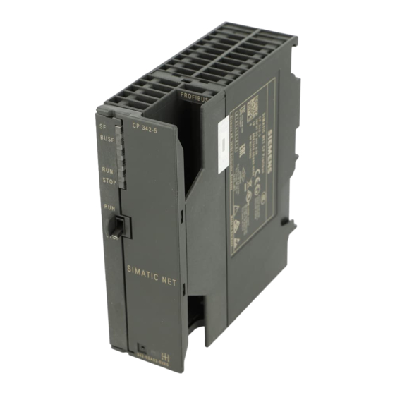
Preface Product overview and notes CP 343-5 Article number: 6GK7343-5FA01-0XE0 Hardware product version: 4 Firmware version: V4.1 Communications processor for connecting SIMATIC S7-300 / C7-300 to PROFIBUS DP ① 9-pin D-sub socket ② Status and error displays ③ Mode switch ④... - Page 4 Link: (https://support.industry.siemens.com/cs/ww/de/view/1158693) • Manual Part B - Equipment manual "CP 343-5" (this document) Current manual release on the Internet You will also find the current version of this manual on the Internet pages of Siemens Industry Online Support: Link: (https://support.industry.siemens.com/cs/ww/en/ps/15676/man)
- Page 5 Siemens contact. Keep to the local regulations. You will find information on returning the product on the Internet pages of Siemens Industry Online Support: Link: (https://support.industry.siemens.com/cs/ww/en/view/109479891)
- Page 6 Preface CP 343-5 Equipment Manual, 05/2023, C79000-G8976-C160-04...
-
Page 7: Table Of Contents
Table of contents Preface ..............................3 Properties / services ..........................9 Use ............................9 Communications services ..................... 9 Performance data ..........................11 Transmission speeds supported ..................11 Characteristics of FMS connections..................11 Characteristic data of S5-compatible communication (SEND/RECEIVE interface) over FDL connections ........................ - Page 8 Table of contents CP 343-5 Equipment Manual, 05/2023, C79000-G8976-C160-04...
-
Page 9: Properties / Services
Properties / services Automation system The CP 343-5 communications processor is intended for operation in a SIMATIC S7-300 / C7-300 automation system. It allows connection of the S7-300 / C7-300 to a PROFIBUS fieldbus system. Communications services Supported communications services In its current configuration, the CP 343-5 supports the following communications services: •... - Page 10 You will find information on the current block versions and the current blocks to download in our Customer Support on the Internet: Link: (https://support.industry.siemens.com/cs/ww/en/view/62543517) With older module types, this recommendation assumes that you are using the latest firmware version for the particular module type.
-
Page 11: Performance Data
Performance data Transmission speeds supported The transmission speed is set with the SIMATIC STEP 7 configuration software. For the permitted values, refer to Table 6-1 in Section 6 (Page 27) Characteristics of FMS connections General characteristic data The following characteristic data is important when operating FMS connections: Component Explanation / values Number of operable FMS... -
Page 12: Characteristic Data Of S5-Compatible Communication (Send/Receive Interface) Over Fdl Connections
Performance data 2.3 Characteristic data of S5-compatible communication (SEND/RECEIVE interface) over FDL connections Other notes on FMS Note: In FMS server operation, the CP occupies an unconfigured communication bus connection in the S7 CPU. Note that the S7 CPU 314 supports a maximum of 4 (maximum of 12 with newer CPU types) unconfigured communication bus connections. -
Page 13: Characteristic Data Of S7 Communication
Performance data 2.4 Characteristic data of S7 communication Speed of the FDL connections Refer to the following table for transmission rates with FDL connections dependent on the following parameters: • Frame length (number of bytes) • CPU type The values were measured while sending or receiving successively (at a transmission rate of 1.5 Mbps;... - Page 14 Performance data 2.5 Parallel use of communications services (multiprotocol mode) CP 343-5 Equipment Manual, 05/2023, C79000-G8976-C160-04...
-
Page 15: Displays And Mode Selector
Displays and mode selector LEDs LED display of the operating status of the CP The different combinations of the four LEDs on the front panel indicate the status of the CP: SF (red) BUSF (red) RUN (green) STOP (yellow) CP operating mode Starting up (STOP->RUN) Running (RUN) Stopping (RUN->STOP) -
Page 16: Mode Selector
Displays and mode selector 3.2 Mode selector Mode selector Controlling the mode Note Modes Note the explanations in the manual /2/ (Page 35) on the topic of operating modes. You can control the mode of the CP 343-5 in the following ways: •... -
Page 17: Installation, Connection, Commissioning, Removal
Installation, connection, commissioning, removal Important notes on using the device The following safety notices must be adhered to when setting up and operating the device and during all associated work such as installing, connecting, replacing or removing devices. 4.1.1 Notes on use in hazardous areas WARNING The device may only be operated in an environment with pollution degree 1 or 2 as described in EN/IEC 60664-1, GB/T 16935.1. -
Page 18: Notes On Use In Hazardous Areas According To Ul Hazloc And Fm
Installation, connection, commissioning, removal 4.1 Important notes on using the device WARNING Suitable cables at high ambient temperatures in hazardous area Use heat-resistant cables with an ambient temperature ≥ 60 °C; these cables must be rated for an ambient temperature that is at least 20 °C higher. The cable entries used on the housing must comply with the IP degree of protection required by EN IEC 60079-0 / GB 3836.1. -
Page 19: Installation, Removal And Repairs In Hazardous Areas
Installation, connection, commissioning, removal 4.2 Installation, removal and repairs in hazardous areas WARNING EXPLOSION HAZARD The equipment is intended to be installed within an ultimate enclosure. The inner service temperature of the enclosure corresponds to the ambient temperature of the module. Use installation wiring connections with admitted maximum operating temperature of at least 30 ºC higher than maximum ambient temperature. -
Page 20: Installing, Connecting And Commissioning
• Observe the device approvals applicable for your country. WARNING Unauthorized repair of devices in explosion-proof design Risk of explosion in hazardous areas • Repair work may only be performed by personnel authorized by Siemens. Installing, connecting and commissioning NOTICE Improper mounting Improper mounting may damage the device or impair its operation. - Page 21 Installation, connection, commissioning, removal 4.3 Installing, connecting and commissioning WARNING Open equipment The devices are "open equipment" acc. to the standard IEC 61010-2-201 or UL 61010-2-201 / CSA C22.2 No. 61010-2-201. To fulfill requirements for safe operation with regard to mechanical stability, flame retardation, stability, and protection against contact, the following alternative types of installation are specified: •...
-
Page 22: Disassembly
Installation, connection, commissioning, removal 4.4 Disassembly Step Procedure / significance 3. Connect the CP to the power supply. Follow the steps as described in detail in /1/ (Page 35) when wiring between the power supply and the CPU. Note Connecting the CP to the power supply •... -
Page 23: Diagnostics And Maintenance
Diagnostics and maintenance CAUTION Hot surfaces Risk of burns during maintenance work on parts with a surface temperature above 70 °C (158 °F). • Take appropriate protective measures, for example, wear protective gloves. • Once maintenance work is complete, restore the touch protection measures. WARNING Cleaning the housing •... -
Page 24: Replacing Older Modules / Module Replacement
Diagnostics and maintenance 5.1 Compatibility with previous product 5.1.2 Replacing older modules / module replacement Module replacement Follow the procedure below when replacing an older module with one of the modules described here. Module used up to now Configuration procedure 6GK7 343-5FA00-0XE0 Configuration unchanged (spare part scenario) If you have no requirements beyond what you had with the previous CP, you do not... - Page 25 You should always use the latest block versions for new user programs. You will find information on the current block versions and the current blocks for download in Customer Support on the Internet: Link: (https://support.industry.siemens.com/cs/ww/en/ps/15676/pm) CP 343-5 Equipment Manual, 05/2023, C79000-G8976-C160-04...
- Page 26 Diagnostics and maintenance 5.1 Compatibility with previous product CP 343-5 Equipment Manual, 05/2023, C79000-G8976-C160-04...
-
Page 27: Technical Specifications
Technical specifications General technical specifications Technical specifications Value Transmission speeds supported 9.6 kbps, 19.2 kbps, 45.45 kbps, 93.75 kbps, 187.5 kbps, 500 kbps 1.5 Mbps, 3 Mbps, 6 Mbps, 12 Mbps Interfaces • Connection to PROFIBUS • 9-pin D-sub socket •... - Page 28 Technical specifications CP 343-5 Equipment Manual, 05/2023, C79000-G8976-C160-04...
-
Page 29: Approvals
You will find the declarations of conformity listed below and certificates of the product on the Internet at the following address: Link: (https://support.industry.siemens.com/cs/ww/en/ps/15676/cert) You can see the current versions of the standards in the relevant certificate, which you will find on the Internet at the address specified above. - Page 30 Directive of the European Parliament and of the Council of 8 June 2011 on the restriction of the use of certain hazardous substances in electrical and electronic equipment UK Declaration of Conformity Importer UK: Siemens plc Sir William Siemens House Princess Road Manchester M20 2UR The product meets the requirements of the following directives: •...
- Page 31 • EN IEC 60079-0 - Explosive atmospheres - Part 0: Equipment - General requirements • EN 60079-7 - Explosive Atmospheres - Part 7: Equipment protection by increased safety 'e' Importer UK: Siemens plc (see above) Classification: Ex na IIC T4 Gc The product meets the requirements of the following standards: •...
- Page 32 Approvals The CP meets the requirements of the following directives: • EU directive 2014/30/EU "Electromagnetic Compatibility" (EMC directive) • EMC Regulations SI 2016/1091 The Electromagnetic Compatibility Regulations 2016 Applied standards: • EN 61000-6-2 Electromagnetic compatibility (EMC) - Part 6-2: Generic standards - Immunity for industrial environments •...
- Page 33 SIMATIC NET products are regularly submitted to the relevant authorities and approval centers for approvals relating to specific markets and applications. If you require a list of the current approvals for individual devices, consult your Siemens contact or check the Internet pages of Siemens Industry Online Support: Link: (https://support.industry.siemens.com/cs/ww/en/ps/15676/cert)
- Page 34 Approvals CP 343-5 Equipment Manual, 05/2023, C79000-G8976-C160-04...
-
Page 35: Bibliography
• Documentation in the STEP 7 V5 installation Manuals that are included in the online documentation of the STEP 7 installation on your PG/PC can be found in the start menu ("Start" > "All Programs" > "Siemens Automation" > "Documentation"). - Page 36 Bibliography CP 343-5 Equipment Manual, 05/2023, C79000-G8976-C160-04...
-
Page 37: Index
Index Disposal, 5 Recycling, 5 CP 343-5 Equipment Manual, 05/2023, C79000-G8976-C160-04...
Need help?
Do you have a question about the SIMATIC NET S7-300 - PROFIBUS and is the answer not in the manual?
Questions and answers