Minelab F3 Service Manual
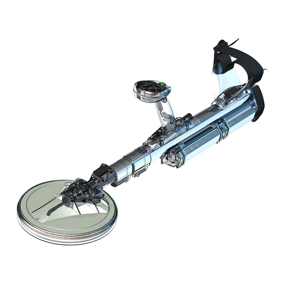
Metal mine detector
Hide thumbs
Also See for F3:
- Service manual (71 pages) ,
- Operation manual (49 pages) ,
- Instructions manual (36 pages)
Table of Contents
Advertisement
Quick Links
Advertisement
Table of Contents

Subscribe to Our Youtube Channel
Related Manuals for Minelab F3


Summary of Contents for Minelab F3
- Page 1 F3 Metal Mine Detector F3 Service manual Revision 5: July 2018 Part No: 4904-0004...
- Page 2 F3 Service Manual WARNING THIS DOCUMENT CONTAINS MINELAB ELECTRONICS LIMITED RIGHTS TECHNICAL DATA OR RESTRICTED RIGHTS DATA OR BOTH. Minelab Electronics This work is copyright. Apart from any use as permitted under the Copyright Act 1968, no part may be reproduced by any process without written...
-
Page 3: Table Of Contents
Warnings ..............................5 Mine Detecting Set ..........................6 F3 Main Components ..........................7 F3 Accessories............................7 Introduction to F3 Service and Repair ....................10 MECHANICAL & FUNCTIONAL TESTING ................ 12 Mechanical Testing..........................12 Functional Testing..........................14 Detector Field Test..........................21 Introduction ............................ - Page 4 F3 Service Manual Trouble Shooting Table......................... 68 MAINTENANCE PLAN FOR F3 DETECTORS..............72 Daily Maintenance ..........................72 Weekly Maintenance ..........................72 Action When a Detector Fault is Discovered ..................72 Scheduled Maintenance........................73 Detector Fault Report........................... 76...
-
Page 5: Introduction
Internal High Voltages. Voltages potentially capable of causing electric shock are present inside the F3 electronics pack and coil. Do not use the F3 detector if the coil or coil cable is damaged with exposed conductors. Do not turn on the F3 whilst the electronics pack is opened and internal circuits are exposed. -
Page 6: Mine Detecting Set
F3 Service Manual Mine Detecting Set The F3 is supplied as a complete mine detecting set comprising: Figure 1: F3 Packed in its Hard Case Table 1: F3 Detecting Set 3111-0602 F3 Metal Detector Set (complete) 3015-0000 F3 Detector (detector only) -
Page 7: F3 Main Components
Figure 2 identifies the main components of the F3 which comprise: Figure 2: F3 Major Components & Handle Controls F3 Accessories The F3 has a range of accessories and ancillary equipment to support it in the field this includes: Table 2: Accessories 4523-0027 Earset Speaker On. - Page 8 Cable Battery Pack F3, battery extension cable 3001-0036 Bag Battery Pack F3, used with battery cable. 3011-0097 Coil Kit F3 UXO. A kit including a large UXO coil that enables an F3 (small coil) to be converted to an F3 UXO detector. 3004-0018 Tool Kit F3.
- Page 9 F3 Service Manual Specifications of F3 Metal Detector Table 3: Specifications of the F3 detector Manufacturer Minelab Electronics Pty. Ltd Model F3, F3L and F3 UXO 6665 66 1580722 Description Pulse Induction Metal Detector Transmission Bi-Polar Multi Period Sensing Transmit Frequency 1.25 Khz +/- 3% Pulse Repetition Frequency...
-
Page 10: Introduction To F3 Service And Repair
3004-0017 Speaker Pod Kit F3 The F3 detector can be repaired and serviced in the field (under clean and dry conditions) or at local depots. No special tools are required, but it is recommended that the F3 Service Tool Kit be used. - Page 11 F3 Service Manual This manual should be read in conjunction with the F3 Operations Manual. Additionally, from time to time, Minelab will issue technical service notes which serve to supplement the information contained in this manual. Any questions regarding this manual or any repair procedure can be directed to Minelab via the following internet link: https://www.minelab.com/countermine...
-
Page 12: Mechanical & Functional Testing
Confirm that all components are present in the hard case and unpack, fully extend and insert batteries into the F3 as described in the F3 Operations Manual. Figure 3 identifies the major components of the F3. During mechanical testing check the: ... - Page 13 F3 Service Manual Figure 3: F3 Major Components & Handle Controls. To replace any worn or damaged parts found during mechanical testing refer to section 4 Disassembly & Reassembly Procedures. Page 13...
-
Page 14: Functional Testing
F3 Service Manual Functional Testing. Functional testing is used to confirm the serviceability of an F3 before it is returned to the field for use and whenever doubt exists about the serviceability of an F3. The F3 must pass all tests to be considered serviceable and ready for use in operations. - Page 15 During the 45 seconds, the detector scans the environment searching for the source of any electrical interference. Once detected, the F3 will automatically select a different operating frequency to eliminate or reduce the interference. If the correct sequence of Noise Cancel beeps is not heard refer to section Fault Finding Procedures.
- Page 16 F3 Service Manual NOTE If the ground balance button is not immediately released, the F3 will commence the Ground Balance procedure. Figure 6: Audio Reset. Within two seconds the threshold tone should return to its correct level. If the threshold tone does not return to the correct level refer to section 5 Fault Finding Procedures.
- Page 17 F3 Service Manual ground balance test piece away from the centre of the coil to a distance of 15cm (6ins). Repeat this process until the ‘Ground Balance OK’ tone consisting of a short high-pitched double beep occurs. This tone confirms the ground balance procedure has been completed correctly.
- Page 18 The black endcap has no magnets and represents the default sensitivity of the F3. This means the black endcap, if dislodged, will not cause an alarm because the detector is already operating at the default sensitivity.
- Page 19 Earset speaker off is not connected to the detector. Switch the F3 off and on – this will revert the detector to default sensitivity. Move the detector coil over a large metal target checking that the LEDs light up in the correct sequence.
- Page 20 F3 Service Manual Test Piece Test. This is a critical test and should be conducted last to confirm the detector is performing correctly and at an acceptable sensitivity level. It should be conducted in an environment that is free from electrical interference and an earset must be connected.
-
Page 21: Detector Field Test
Minelab’s application software. The Test Piece Test as described above is not suitable for use with the F3 and a yellow endcap. Where sensitivity testing is to be conducted using a specific customised configuration, it is the responsibility of the... -
Page 22: Introduction
Flat blade screwdriver 6.5mm x 150m 4904-0004 Service Manual F3 Figure 10: Tool Kit. NOTE All tools except the F3 Coil Cable Pull Through are commonly available. If necessary, a length of string can be used as the F3 Coil Cable Pull Through. Page 22... -
Page 23: Electronics Pack
Figure 11 illustrates the major parts involved in removing and replacing the electronics pack. The F3 and F3L use different electronics packs and should not be interchanged unless the correct speaker pods (F3L requires the speaker pod with LED display) are also fitted. - Page 24 F3 Service Manual NOTE The F3L electronics pack can be identified by a yellow dot or L on the rear of the housing. To Remove the Electronics Pack: Remove battery pack and sensitivity endcap. Remove the six screws (Part 10) holding the cover bulkhead (Part 9) to the electronics pack rear panel.
- Page 25 If a retainer plug is not fitted connect the coil cable pull through from the F3 Tool Kit to secure the coil cable. Alternatively, the cable can be secured by tying the plug to a length of string.
- Page 26 F3 Service Manual Coil Connector Figure 15: Connecting Electronics Pack to shaft and connect coil. Slide the electronics pack along the upper shaft into place, ensuring the wiring loom cable lays in the cut out at the top of the electronics pack rear cover.
- Page 27 F3 Service Manual NOTE Take great care when connecting the wiring loom plug to the electronics pack. DO NOT force the connection because this could damage or break the connector. Figure 17: Wiring Loom Cable positioned and 6 screws inserted.
- Page 28 The shorting links can be adjust to configure the electronics pack for an F3 or an F3L (with LEDs). The F3 detector will have a threshold confidence tone or a heartbeat confidence tone depending on the adjustment of the shorting links on the printed circuit board.
- Page 29 F3 Service Manual Figure 20: Removing battery connector locking mechanism. Slide the electronics pack housing backward exposing the circuit boards. Figure 21: Removing the Electronics Pack housing. The circuit boards and internal components of the electronics pack can now be checked and the configuration links (switches) can be adjusted or checked.
- Page 30 F3L link Figure 22: Configuration links. Three configuration links must be connected, two links set the detector to F3 or F3L. One link sets the confidence tone to threshold tone or Heartbeat tone. If the detector has an LED display on the handle then the configuration links must be set to F3L.
-
Page 31: Coil
To Replace the Skid Plate: All Minelab coils should have a skid plate attached to the underside of the coil, the skid plate is designed to protect the coil from wear and tear caused by contact with the ground. The skid plate may need replacing particularly after prolonged heavy use. - Page 32 F3 Service Manual Figure 24: Replacing the Skid Plate. To remove the coil: Retract the shafts and remove the battery pack and endcap. Remove the electronics pack as described in section 4.3a To remove the electronics pack. However, there is no need to remove the electronics pack from the upper shaft.
- Page 33 F3 Service Manual Figure 26: Removing the Coil Retainer Lift the lower shaft with lower camlock assembly out of the coil top. Carefully pull the coil cable out from inside the shafts, as shown in Figure 27. ...
- Page 34 F3 Service Manual Attach a coil pin into the spirals of the coil cable as shown in Figure 29: inserting the coil pin into the top spirals of the coil cable. position the coil pin so that the straight portion of cable is aligned with the channel in the coil pin.
- Page 35 F3 Service Manual Figure 31: Threading Coil Cable through Shafts. NOTE It is important that the curly cable or coil cable pull through is not twisted, as this will change the number of turns in the curly cable. If the correct number of turns is not present, the curly cable may stop the shafts from retracting correctly.
-
Page 36: Uxo Coil
The F3 UXO coil is a 44cm (18inch) mono loop coil, this will give a stronger signal and greater depth of detection for large metal targets but a weaker signal for very small targets. -
Page 37: F3 Uxo Coil Mkii
F3 Service Manual 3.8.1 F3 UXO Coil MkII Parts of 3011-0380 Coil F3 UXO Mk2 Every Coil UXO Mk2 includes all the hardware to mount and connect it to any F3 detector: 3011-0380 Coil Assembly F3 UXO Mk2 4308-0012 Pin coil cable support... - Page 38 F3 Service Manual Page 38...
- Page 39 F3 Service Manual Page 39...
-
Page 40: F3 Uxo Coil
F3 Service Manual 3.8.2 F3 UXO Coil. Figure 35: F3 UXO detector. Figure 36: UXO Coil. Table 3: UXO Coil. 3011-0097 UXO Coil Kit 2021-0086 Coil UXO 3001-0062 Bag Carry F3-UXO Page 40... - Page 41 Attach the friction blocks (6) to the lower camlock body at the end of the lower shaft of the F3 detector and then fit the adapter coil yoke (10) on to the friction blocks. As shown in figure 37.
-
Page 42: Speaker Pod
F3 Service Manual Figure 38: Attaching UXO Coil. Reconnect the electronics pack to the coil cable as described in Section 4.3.b To Connect an Electronics Pack. Note The Skid Plate of the UXO coil is held in place by a small amount of silicone glue. - Page 43 Older F3 Speaker Pods only. Remove the screw (Figure 28) which secures the lower half of the speaker pod to the handle. The nut for this screw sits in a recess between the two handle halves. This screw is a unique screw and cannot be used on any other part of the detector.
- Page 44 When replacing or reassembling speaker pods it is important to note that an F3L speaker pod is only functional on an F3L configured detector. Similarly, the standard F3 speaker pod is only functional on the F3 detector. reassemble the speaker pod: ...
- Page 45 Figure 43. Figure 43: Correct Position of Wiring Loom Plug (Red Arrow). On older F3 speaker pods, using the unique screw (Figure 43) secure the speaker pod to the handle. Newer F3 detectors do not require this screw. ...
- Page 46 F3 Service Manual Ensure the O-Ring is clean, lightly greased and in the correct position, next to the speaker. Gently push the upper half of the pod down towards the handle until both halves of the pod are correctly mated.
-
Page 47: Handle
F3 Service Manual 3.10 Handle. Figure 45 illustrates the major parts of the handle. Figure 45: Handle. Table 5: Handle Kit. 3004-0032 Handle Kit F3 (for F3 only) 3004-0043 Wiring Loom 3004-0017 Speaker Pod Kit 4002-0023 Nut M4 Nyloc Ss 2&3... - Page 48 Ensure the on/off switch slider (Part 6) is correctly positioned. Fit the earset dust cap into the recess in the handle just forward of the earset plug. Shown in Figure 47. Old F3 detectors only, place the captive nut in the top of the handle. Page 48...
-
Page 49: Wiring Loom
F3 Service Manual Figure 47: Recess for Dust Cap. Carefully fit the left handle half to the right handle half and upper shaft. Ensure both halves are secured to the upper shaft. NOTE Hold the handle together tightly until the first two bolts have been fitted otherwise the internal nut or main wiring loom may become dislodged. - Page 50 3004-0036 F3L Electronics Pack Kit (only used on F3L) NOTE The F3 and F3L use different electronics packs and should not be interchanged unless the correct speaker pods (F3L requires the speaker pod with LED display) are also fitted. Page 50...
- Page 51 F3 Service Manual Remove battery pack and sensitivity endcap. Undo and remove the six screws holding the bulkhead cover to the electronics pack rear panel. Shown in Figure 49. Cover Wiring Bulkhead Loom Figure 49: Removal of Cover Bulkhead from the Electronics Pack.
- Page 52 Gently pull the wiring loom through the spine of the upper shaft toward the handle and remove it. The wiring loom is removed from the F3 and can now be replaced if required. Page 52...
- Page 53 F3 Service Manual To Connect the Wiring Loom: With a new wiring loom, gently push the cable (connector first) through the spine of the upper shaft emerging at the opening at the end of the upper shaft. Shown in Figure 52...
- Page 54 F3 Service Manual Fasten two screws into the cover ribbon cable. Shown in Figure 54. Tightening these screws squeezes the grommet around the wiring loom creating a water tight seal. Figure 54: Cover Bulkhead. Slide the electronics pack all the way along the upper shaft, ensuring the wiring loom cable lays in the cut out at the top of the electronics pack rear cover.
- Page 55 F3 Service Manual O-Ring Wiring Loom Connector folded inside Keyway Keyway Cut-out Figure 56: Connecting Wiring Loom to the Electronics Pack. NOTE Take great care when connecting the wiring loom plug to the electronics pack. DO NOT force the connection because this could damage or break the connector on the printed circuit board.
- Page 56 F3 Service Manual Assemble the handle, follow the instructions given in Section 4.7.b.To Assemble the Handle. The Wiring loom has been replaced, conduct the functional and mechanical testing of the F3 before using the detector. Page 56...
-
Page 57: Armrest
F3 Service Manual 3.12 Armrest. Figure 58 illustrates the major parts of the armrest. Figure 58: Armrest. Table 7: Armrest. 3004-0034 Armrest Kit F3, All items in this table 31-24000-780 Nut M4 Nyloc 31-24030-980 Bolt M4x30 Skt Cap 4308-0003 Pin Cam Lever 4&5... - Page 58 F3 Service Manual To Assemble the Armrest: Position the right half of the armrest onto the upper shaft. Fit the armrest pressure block, cam lever pivot pin and cam lever into the right armrest half. Carefully fit the left armrest half to the right armrest half and upper shaft.
-
Page 59: Shafts
F3 Service Manual 3.13 Shafts. The following procedures detail shaft disassembly/assembly and should be followed in order until the component to be replaced is accessible. Figure 60 illustrates the components of the shaft assembly. Camlock Upper Camlock Middle Upper Shaft... - Page 60 F3 Service Manual Remove the electronics pack. Refer to section 4.3.a. To Remove the Electronics Pack Remove the coil. Refer to section 4.4.a. To Remove the Coil. Using Figure 61 as a guide, use the 3mm hex driver (Allen key) or punch to push out the two pins (Part 5) from the camlock lower ...
- Page 61 F3 Service Manual Using Figure 62 as a guide, use the 3mm hex driver (Allen key) or punch to push out the pin (Part 5) from the camlock middle. Remove the cam lever. Remove the pressure block by pushing it out from inside the shaft.
- Page 62 F3 Service Manual To Reassemble the Camlock Upper: Press the camlock body upper on to the upper shaft, ensuring that that the square hole in the camlock body is aligned with the cut-out in the upper shaft. Shown in figure 64.
- Page 63 F3 Service Manual Using Figure 66 as a guide, attach the two collars (Part 3) to the rear of the middle shaft. Middle Shaft Upper Shaft Figure 66: Middle Shaft. Slide the middle shaft into the rear of the upper shaft with the square hole facing down.
- Page 64 F3 Service Manual Ensure that the pressure block does not protrude too far into the shaft. If required, push it back into the camlock body otherwise difficulty may be encountered when fitting the lower shaft. Figure 68: Pushing Pin Cam Lever in.
- Page 65 F3 Service Manual Figure 70: Inserting the Lower Shaft. Holding the detector and lower camlock assembly upside down (to prevent the lower pressure block falling out) slide the camlock lower fully onto the lower shaft with a twisting motion.
- Page 66 F3 Service Manual Refit the friction blocks to the camlock lower. The flat side of the friction blocks should face down. Shown in Figure 73. Figure 73: Connecting Friction Blocks. Connect the coil, refer to section 4.4.c To Connect a Coil.
-
Page 67: Battery Pack
F3 Service Manual 3.14 Battery Pack. The battery pack is a line replaceable unit and is not normally disassembled for repair. The major component parts of the battery pack are shown in Figure 74. Figure 74: Battery Pack. Table 11: Battery Pack. -
Page 68: Fault Finding Procedures
Electronics Pack The F3 is designed so that line replaceable units can be exchanged between detectors without the need to calibrate. This means that where spare parts are not available and more than one detector is faulty, then parts from one detector can be used to make another serviceable. - Page 69 F3 Service Manual After switching on the check for tone using the earset F3 makes no sound if there is tone through earset - replace speaker from speaker if there is no tone through earset - replace wiring loom ...
- Page 70 F3 Service Manual Noise Cancel does not Note: Noise Cancel may not completely remove the work effects of interference if the source is powerful or in close proximity (no Noise Cancel tones emitted) repeat Noise Cancel replace wiring loom ...
- Page 71 F3 Service Manual remove coil and remove any dirt located in the shaft and on the cable – inspect cable for any damage – if none ensure the coil has 52 turns and assemble back into the detector – fit coil pin if not present ...
-
Page 72: Maintenance Plan For F3 Detectors
F3 Service Manual 5 Maintenance Plan for F3 Detectors. Daily Maintenance Conduct standard procedure every time the detector is switched on as follows: Switch on Ground Balance Check detector with test piece Operator is to check detector for damaged or missing parts at the start of every day. -
Page 73: Scheduled Maintenance
F3 Service Manual Scheduled Maintenance. Scheduled Maintenance must be conducted at least once every six months. This will normally be planned to coincide with the demining teams leave or stand down. If higher fault rates are experienced on the detectors scheduled maintenance should be conducted more often, as considered necessary. - Page 74 F3 Service Manual there is a problem with the upper camlock replace the Pressure block in the upper camlock. This part may wear out with normal use. Open middle and upper camlocks and fully extend and close the shafts several times making sure there is no snagging or obstruction.
- Page 75 F3 Service Manual Scheduled Maintenance has now been completed. The detector can now be returned to the field. Page 75...
-
Page 76: Detector Fault Report
F3 Service Manual Detector Fault Report. When an F3 detector is faulty and a repair is carried out it is essential that good records are kept of the faults encountered, the parts used and the corrective actions (work done) the following form provides a template of a detector Fault Report:... - Page 77 F3 Service Manual Patents Disclaimer Page 77...
Need help?
Do you have a question about the F3 and is the answer not in the manual?
Questions and answers