Table of Contents
Advertisement
Quick Links
Advertisement
Table of Contents

Subscribe to Our Youtube Channel
Related Manuals for Magicfx FLAMEBLAZER


Summary of Contents for Magicfx FLAMEBLAZER
- Page 1 USER AND INSTALLATION MANUAL ENGLISH FLAMEBLAZER. ® PART01875 FLAME FX rev 01-01...
-
Page 2: Disclaimer
Failure to read the manual and to follow the printed instructions may lead to personal injury and/or damage to the product. © 2022 MAGICFX ® All rights reserved. Nothing from this publication may be copied, reproduced and/or published by means of printing, photocopying or by any other means, without the prior written approval of MAGIC FX. -
Page 3: Table Of Contents
TABLE OF CONTENTS Disclaimer Trademarks Liability Introduction Target group Language Abbreviations Revision table Description Main parts FLAMEBLAZER fuel Technical data 1.4 Product identification 1.5 Accessories ARM control DMX control Display panel 1.9 RDM capability Safety General safety rules Rigging Noise Levels 2.4... -
Page 4: Introduction
FLAMEBLAZER and the required ARM SYSTEM. Authorised personnel are those who: • Are appointed by their supervisor to install and/or operate FLAMEBLAZER and the related ARM SYSTEM at the event. • Are trained in recognizing and avoiding hazards related to SFX applications at events. -
Page 5: Language
MAGICFX FLAMEBLAZER ® Abbreviations REVISION TABLE Doc nr Revision Date Description Author Approved PART01875 01-00 03-6-2020 Initial release MB, ES PART01875 01-01 27-10-2020 Updated graphics PART01875 01-02 10-11-2022 Updated ARM SYSTEM PvdW MAGICFX FLAMEBLAZER — User and Installation Manual ®... -
Page 6: Description
A specific nozzle exchange tool is available to change between the S, M and L nozzles (SFX 1404) The FLAMEBLAZER is operated with DMX and RDM, or with an external low voltage pyro controller (9-40 Vdc). The FLAMEBLAZER can be operated in sequence with multiple machines. -
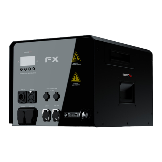
Page 7: Main Parts
Main parts FLAMEBLAZER FUEL The FLAMEBLAZER uses two types of fuel to create the effect. The fuel is loaded into an ADR Can 5 L located in the machine. Only use these types of fuel: Isopropanol, ISOPAR G, H & L. The use... -
Page 8: Technical Data
Configure Options On Device & RDM Usage Consumable(s) Isopropanol, ISOPAR G, H & L Consumable Consumption S nozzle: ≈ 12 ml/s M nozzle: ≈ 30 ml/s L nozzle: ≈ 50 ml/s Technical data MAGICFX FLAMEBLAZER — User and Installation Manual ®... -
Page 9: Product Identification
® MFX3106 Doughty Half Coupler (100 kg) M10 SPR00119 Safety Steel SPR01885 Empty ADR Can 5 L (w/out Cap) SPR90106 FLAMEBLAZER CUSTOM CAN CAP 5L MFX3080 MAGICFX Flame Fluid IPA 5L ® MFX3086 MAGICFX Flame Fluid Isopar L 5L ®... -
Page 10: Arm Control
ARM CONTROLLER in an ARM SYSTEM. The FLAMEBLAZER is configured for safety control with an ARM SYSTEM. The FLAMEBLAZER cannot be operated without the safety signal from the control unit of the ARM SYSTEM: The ARM CONTROLLER. When there’s no signal, the internal relief valve opens. -
Page 11: Display Panel
SELECT Display panel The display panel is located on the backside of the FLAMEBLAZER. Check the following menu structure for all options in the menu. Use the buttons for navigation and selection. The signal LED blinks red when DMX signal is active. The info LED continuously lights red when an error is present. - Page 12 Pyro Input Control (ON/OFF) Display Dimmer (ON/OFF) Configuration Main Menu Factory Defaults (YES/NO) Error History Type (Alarm/Error) Serial Number Unique ID Information Bootloader CRC Build Date Uptime (DDDD:HH:MM:SS) Effect Time (DDDD:HH:MM:SS) Menu structure MAGICFX FLAMEBLAZER — User and Installation Manual ®...
- Page 13 Time counter which indicates how long the appliance has been (DDDD:HH:MM:SS) powered in total. Effect Time Time counter which indicates how long the effect has been on in (DDDD:HH:MM:SS) total. Menu functions MAGICFX FLAMEBLAZER — User and Installation Manual ®...
-
Page 14: Rdm Capability
RDM can be used for configuration and status monitoring while DMX512 takes care of the default controlling. For RDM you will need a RDM compatible controller. The following RDM parameters are supported by the FLAMEBLAZER. Parameter ID Discovery... -
Page 15: Safety
SAFETY The FLAMEBLAZER has been designed and constructed in such a manner that it can be used safely. This applies to the use, the circumstances and the regulations as described in this documentation. Reading this documentation and following the instructions are therefore necessary for everyone who is authorised to work with the FLAMEBLAZER. -
Page 16: Safety Symbols
Fuels are highly flammable and must be handled with caution WARNING and in accordance with local health and safety regulations. Always follow the safety instructions from the fuel packaging when handling and working with the fuel. MAGICFX FLAMEBLAZER — User and Installation Manual ®... - Page 17 FLAMEBLAZER. Make sure there are no substances or gasses present that can be WARNING ignited by the emitted flame and fuel from the FLAMEBLAZER. Using a damaged or an improper installed machine can lead to WARNING death, serious injury or property damage.
- Page 18 Only open the enclosure access lid when the machine is not CAUTION powered. The FLAMEBLAZER should not be used in winds exceeding 20 m/h CAUTION or 32 km/h. Always keep the machine dry and do not let excessive amounts NOTICE of liquids such as rain or snow wet the machine.
-
Page 19: Installation And Use
-45° -45° INSTALL THE MACHINE Install the FLAMEBLAZER on a firm and preferably level surface. Inspect the machine and remove any foreign objects and material that will block or obscure the nozzle or ignition probes of the machine during operation. -
Page 20: Choose The Flame Height
10 m flame. Choose a flame height that is safe for the environment and rigging position of the FLAMEBLAZER and select the nozzle that will ensure the flame cannot exceed the physical limitations of this location. - Page 21 To remove the nozzle from the burn chamber place the FLAMEBLAZER Nozzle exchange tool over the hex head of the nozzle being careful not to touch or miss- align the ignition probes. The machine should be on level ground and the burn chamber NOTICE clean of foreign objects and materials.
- Page 22 FLAMEBLAZER Nozzle exchange tool ready for installation, checking it has a washer seal. Carefully lower the FLAMEBLAZER Nozzle exchange tool with nozzle into the burn chamber until the nozzle locates into the bulkhead orifice. Rotate anti-clockwise until a click is heard or felt to check the threads are aligned.
-
Page 23: Re)Fill The Fuel
The flame output burn chamber and enclosure heats up during CAUTION operation and could cause burns when touched. Do not touch any metal parts of a (recently) triggered machine. Disconnect the machine from the power supply. Open the enclosure access lid. MAGICFX FLAMEBLAZER — User and Installation Manual ®... - Page 24 Place the can into the housing so the cap is furthest away from the control panel. MAGICFX FLAMEBLAZER — User and Installation Manual ®...
- Page 25 Push the fuel hose into the quick release coupling on the machine, checking it has engaged properly. Close the enclosure access lid. MAGICFX FLAMEBLAZER — User and Installation Manual ®...
-
Page 26: Mount On A Truss
Use a MAGICFX BASEPLATE II for mounting on top of an upright ® NOTICE truss, see the User and Installation manual of the MAGICFX ® BASEPLATE II (MFX0305). Screw two clamps into threaded holes on the bottom of the machine. Use two Doughty Half Couplers M10 for truss mounting (product code MFX3106) and place the pair in x or in y direction. - Page 27 Mount the half coupler on a truss and secure with a certified safety cable Secure the FLAMEBLAZER onto the truss. Inspect if the FLAMEBLAZER is mounted firmly and secured correctly. Inspect the machine and remove any foreign objects and material that will block or obscure the nozzle or ignition probes of the machine during operation.
-
Page 28: Connect The Machine
CONTROLLER User and Installation Manual (PART01882). 2. Connect the PowerCon TRUE1 power cable to the power input of the FLAMEBLAZER. Connect the other end to a 100-250 Vac (50-60 Hz) power source. 3. Connect the correct cables between the ARM CONTROLLER, the FLAMEBLAZER, the control equipment, and other ARM SYSTEM components and machines (if applicable). - Page 29 The FLAMEBLAZER is controlled with DMX. The DMX signal and the ARM signal have separate cables. E-STOP BEACON FLAMEBLAZER insert terminator ARM CONTROLLER POWER connect another machine DMX CONTROLLER or insert terminator The FLAMEBLAZER is controlled with pyro (9-40 Vdc).
- Page 30 The FLAMEBLAZER is controlled with DMX. The DMX signal and the ARM signal are combined. BEACON FLAMEBLAZER DMX + ARM ARM CONTROLLER DMX INJECTOR connect another machine POWER or insert terminator DMX CONTROLLER 4. If controlled with DMX: Use the display and buttons or a RDM controller to assign DMX addresses, see Chapter 1.
-
Page 31: Fire With Dmx
3. Set the safety key on the ARM CONTROLLER in the ON position. The pump is activated and pressurizes the system. The FX LED lights in red, indicating the system is now armed and the FLAMEBLAZER and other connected SFX machines are ready to be operated. -
Page 32: Use The Emergency Stop
USE THE EMERGENCY STOP 1. When an emergency occurs or is about to occur with the FLAMEBLAZER, you press the emergency stop button on the ARM CONTROLLER or on an external E-STOP (if present). As a result the pressurized air can’t leave the tank and any related hazard/or property damage is stopped and prevented. - Page 33 MAGIC FX. Contact MAGIC FX if the FLAMEBLAZER is not functioning correctly. Firmware updates can add additional features and fix bugs so regulalry check on the website or with your MAGIC FX account manager to ensure you have the latest version.
-
Page 34: Correct Disposal
Please contact your local authority for further details of your nearest designated collection point. Penalties may be applicable for incorrect disposal of this waste, in accordance with your national legislation. MAGICFX FLAMEBLAZER — User and Installation Manual ®... -
Page 35: Ec Declaration Of Conformity
According to Annex III A Machinery Directive 2006/42/EC MAGIC FX B.V. declares as manufacturer and composer of the technical construction file that the product with the following specifications: Name machine : FLAMEBLAZER® STANDALONE Type : MFX1401 Voltage : 220-250Vac 50/60Hz... - Page 36 WWW.MAGICFX.EU...
Need help?
Do you have a question about the FLAMEBLAZER and is the answer not in the manual?
Questions and answers