Table of Contents
Advertisement
Quick Links
Advertisement
Table of Contents

Related Manuals for Magicfx FLAMEBLAZER


Summary of Contents for Magicfx FLAMEBLAZER
- Page 1 USER AND INSTALLATION MANUAL ENGLISH FLAMEBLAZER. ® PART01875 FLAME FX rev 01-01...
-
Page 2: Disclaimer
Failure to read the manual and to follow the printed instructions may lead to personal injury and/or damage to the product. © 2020 MAGICFX ® All rights reserved. Nothing from this publication may be copied, reproduced and/or published by means of printing, photocopying or by any other means, without the prior written approval of MAGIC FX. -
Page 3: Table Of Contents
TABLE OF CONTENTS Disclaimer Trademarks Liability Foreword Language Revision table Meet the FLAMEBLAZER ® Main parts MAGICFX FLAMEBLAZER FUEL ® Technical data 1.4 Product identification 1.5 Accessories DMX control Display panel 1.8 RDM capability FLAME safely! General safety rules Rigging Noise Levels 2.4... -
Page 4: Foreword
This document contains the original instructions in English. In case you require other languages please contact MAGIC FX. REVISION TABLE Doc nr Revision Date Description Author Approved PART01875 01-00 03-6-2020 Initial release MB, ES PART01875 01-01 27-10-2020 Updated graphics MAGICFX FLAMEBLAZER — User and Installation Manual ®... -
Page 5: Meet The Flameblazer
The machine uses specific flammable fuels that are projected from a single outlet across spark ignition probes to produce the flame jet. An integrated electric pump draws the fuel from the 5 L can and generates the firing pressure. There are three nozzles available with the MAGICFX FLAMEBLAZER which are ®... -
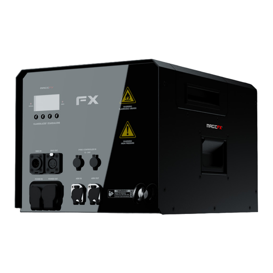
Page 6: Main Parts
Main parts MAGICFX FLAMEBLAZER FUEL ® The MAGICFX FLAMEBLAZER uses two types of fuel to create the effect. The fuel is ® loaded into an ADR Can 5 L located in the machine. Only use these types of fuel: Isopropanol, ISOPAR G, H & L. The use... -
Page 7: Technical Data
TECHNICAL DATA Product Product Name MAGICFX FLAMEBLAZER ® Product Code MFX1401 Product Type FLAME FX Main Length 410 mm 16.4 in Dimensions Width 300 mm 11.8 in Height 281 mm 11 in Weight Empty Weight 18.7 kg 41 lbs Package... -
Page 8: Product Identification
CUSTOM CAN CAP 5L ® MFX3220 MAGICFX FX-ARM CONTROLLER ® MFX3080 MAGICFX® Flame Fluid IPA 5L MFX3086 MAGICFX® Flame Fluid Isopar L 5L Accessories Please contact MAGIC FX for additional possibilities. 8 MAGICFX FLAMEBLAZER — User and Installation Manual ®... -
Page 9: Dmx Control
DMX CONTROL The MAGICFX FLAMEBLAZER is controlled with 1 enable address and 1 operational ® address: DMX address Address range Control Enable address 1 - 512 Device enable/disable Start address 1 - 512 Effect trigger DMX addresses The enable address cannot be the same as the operational address. Operating of... -
Page 10: Display Panel
PREV NEXT SELECT Display panel The display panel is located on the backside of the MAGICFX FLAMEBLAZER . Check ® the following menu structure for all options in the menu. Use the buttons for navigation and selection. The signal LED blinks red when DMX signal is active. The info LED continuously lights red when an error is present. - Page 11 (dims after 30 seconds of button inactivity) Main Menu Factory Defaults (YES/NO) Error History Type (Alarm/Error) Serial Number Unique ID Software Version Information Software CRC Bootloader CRC Build Date Uptime (DDDD:HH:MM:SS) Effect Time (DDDD:HH:MM:SS) Menu structure MAGICFX FLAMEBLAZER — User and Installation Manual ®...
- Page 12 Time counter which indicates how long the appliance has been (DDDD:HH:MM:SS) powered in total. Effect Time Time counter which indicates how long the effect has been on in (DDDD:HH:MM:SS) total. Menu functions MAGICFX FLAMEBLAZER — User and Installation Manual ®...
-
Page 13: Rdm Capability
RDM can be used for configuration and status monitoring while DMX512 takes care of the default controlling. For RDM you will need a RDM compatible controller. The following RDM parameters are supported by the MAGICFX FLAMEBLAZER ® Parameter ID... -
Page 14: Flame Safely
• Are free of dust, corrosive gases and high concentrations of organic vapours. GENERAL SAFETY RULES • Only authorised persons may work with the MAGICFX FLAMEBLAZER ® • Do not use the MAGICFX FLAMEBLAZER if there are people or animals in the ®... -
Page 15: Safety Symbols
Make sure there are no objects near the machine and within the WARNING output distance that can be damaged or catch fire by the emitted flame and fuel from the MAGICFX FLAMEBLAZER ® MAGICFX FLAMEBLAZER — User and Installation Manual... - Page 16 Make sure there are no substances or gasses present that can be WARNING ignited by the emitted flame and fuel from the MAGICFX FLAMEBLAZER ® Using a damaged or an improper installed machine can lead to WARNING death, serious injury or property damage. Always inspect the machine thoroughly before operation.
- Page 17 Always inspect the nozzle before operating and remove any obstructing material. Only open the enclosure access lid when the machine is not CAUTION powered. The MAGICFX FLAMEBLAZER should not be used in winds ® CAUTION exceeding 20 m/h or 32 km/h.
-
Page 18: Let's Flame
0° -45° -45° INSTALL THE MACHINE Install the MAGICFX FLAMEBLAZER on a firm and preferably level surface. ® Inspect the machine and remove any foreign objects and material that will block or obscure the nozzle or ignition probes of the machine during operation. -
Page 19: Choose The Flame Height
Making sure there are no objects near the machine and within the output distance that can be damaged or catch fire by the emitted heat, flame and fuel from the MAGICFX FLAMEBLAZER ® CHOOSE THE FLAME HEIGHT The machine is supplied with an L nozzle installed which NOTICE produces up to a 10 m flame. - Page 20 To remove the nozzle from the burn chamber place the MAGICFX FLAMEBLAZER ® Nozzle exchange tool over the hex head of the nozzle being careful not to touch or miss-align the ignition probes. The machine should be on level ground and the burn chamber NOTICE clean of foreign objects and materials.
- Page 21 Replace the nozzle that is not needed for the new nozzle and locate it in the socket of the MAGICFX FLAMEBLAZER® Nozzle exchange tool ready for installation, checking it has a washer seal.
- Page 22 Carefully lower the MAGICFX FLAMEBLAZER® Nozzle exchange tool with nozzle into the burn chamber until the nozzle locates into the bulkhead orifice. Rotate anti-clockwise until a click is heard or felt to check the threads are aligned. Make sure the tool is held vertical, continuous clockwise rotation will tighten the nozzle into place.
-
Page 23: Re)Fill The Fuel
Fuels are highly flammable and must be handled with caution CAUTION and in accordance with local health and safety regulations. Always follow the safety instructions from the fuel packaging when handling and working with the fuels. MAGICFX FLAMEBLAZER — User and Installation Manual ®... - Page 24 Place the can into the housing so the cap is furthest away from the control panel. MAGICFX FLAMEBLAZER — User and Installation Manual ®...
- Page 25 Push the fuel hose into the quick release coupling on the machine, checking it has engaged properly. Close the enclosure access lid. MAGICFX FLAMEBLAZER — User and Installation Manual ®...
-
Page 26: Mount On A Truss
Use a MAGICFX BASEPLATE II for mounting on top of an upright ® NOTICE truss, see the User and Installation manual of the MAGICFX ® BASEPLATE II (MFX0305). Screw two clamps into threaded holes on the bottom of the machine. Use two Doughty Half Couplers M10 for truss mounting (product code MFX3106) and place the pair in x or in y direction. - Page 27 Mount the half coupler on a truss and secure with a certified safety cable Secure the MAGICFX FLAMEBLAZER onto the truss. ® Inspect if the MAGICFX FLAMEBLAZER is mounted firmly and secured correctly. ® Inspect the machine and remove any foreign objects and material that will block or obscure the nozzle or ignition probes of the machine during operation.
- Page 28 Making sure there are no objects near the machine and within the output distance that can be damaged or catch fire by the emitted heat, flame and fuel from the MAGICFX FLAMEBLAZER ® 28 MAGICFX FLAMEBLAZER — User and Installation Manual...
-
Page 29: Connecting The Machine
Make sure the DMX or Pyro controller is disconnected from power or power switch is disabled. If DMX is used, follow the next steps: Connect an arm cable to the arm in connector on the machine. Connect the other end of the arm cable to the MAGICFX FX-ARM ® CONTROLLER. - Page 30 RJ45 Arm leads can cause damage to them. If pyro is used, follow the next steps: Connect an arm cable to the arm in connector on the machine. Connect the other end of the arm cable to the MAGICFX FX-ARM ®...
-
Page 31: Setup Multiple Machines In A Sequence With Dmx
3. Connect a DMX cable between the DMX output and the DMX input of the next machine. 4. Use the buttons or a RDM controller to assign DMX addresses, see Chapter 1. 5. Repeat step 1 to 4 for each subsequent machine. MAGICFX FLAMEBLAZER — User and Installation Manual ®... -
Page 32: Let's Flame
3. Ensure the e-stop is released, the reset button is not illuminated and move the MAGICFX® FX-ARM CONTROLLER key into the on position. The FX LED indicator on both the MAGICFX® FX-ARM CONTROLLER and MAGICFX FLAMEBLAZER®... - Page 33 3. Ensure the e-stop is released, the reset button is not illuminated and move the MAGICFX® FX-ARM CONTROLLER key into the on position. The FX LED indicator on the MAGICFX® FX-ARM CONTROLLER lights up continuously and the FX LED indicator on the machine flashes immediately.
-
Page 34: Troubleshooting
Always contact MAGIC FX if any malfunctions or errors occur that cannot be solved with the instructions as described in this manual. MAINTENANCE To achieve the maximum service life of the MAGICFX FLAMEBLAZER you must ® regularly clean the MAGICFX FLAMEBLAZER and test if it is functioning correctly. - Page 35 16 mm (+2 mm). If they do not have these gaps or are miss-aligned in anyway contact MAGIC FX. Contact MAGIC FX if the MAGICFX FLAMEBLAZER is not functioning correctly. ®...
- Page 36 MAGICFX FLAMEBLAZER — User and Installation Manual ®...
-
Page 37: Correct Disposal
Please contact your local authority for further details of your nearest designated collection point. Penalties may be applicable for incorrect disposal of this waste, in accordance with your national legislation. MAGICFX FLAMEBLAZER — User and Installation Manual ®... - Page 38 38 MAGICFX FLAMEBLAZER — User and Installation Manual ®...
-
Page 39: Ec Declaration Of Conformity
According to Annex III A Machinery Directive 2006/42/EC MAGIC FX B.V. declares as manufacturer and composer of the technical construction file that the product with the following specifications: Name machine : FLAMEBLAZER® STANDALONE Type : MFX1401 Voltage : 220-250Vac 50/60Hz... - Page 40 WWW.MAGICFX.EU...
Need help?
Do you have a question about the FLAMEBLAZER and is the answer not in the manual?
Questions and answers