Table of Contents
Advertisement
Quick Links
Advertisement
Table of Contents

Subscribe to Our Youtube Channel
Related Manuals for Smartgen HFC6100LT


Summary of Contents for Smartgen HFC6100LT
- Page 1 HFC6100LT FAN CONTROLLER USER MANUAL SMARTGEN (ZHENGZHOU) TECHNOLOGY CO., LTD.
- Page 2 SmartGen Technology at the address above. Any reference to trademarked product names used within this publication is owned by their respective companies. SmartGen Technology reserves the right to change the contents of this document without prior notice. Table 1 - Software Version Date...
-
Page 3: Table Of Contents
8.5 FAN RUNNING TIME ........................21 9 COMMISSIONING ..........................22 10 TYPICAL APPLICATION ........................22 11 INSTALLATION ........................... 23 11.1 FIXING CLIPS ..........................23 11.2 OVERALL DIMENSION AND PANEL CUTOUT................23 12 TROUBLESHOOTING .......................... 24 HFC6100LT Fan Controller User Manual Page 3 of 24... -
Page 4: Overview
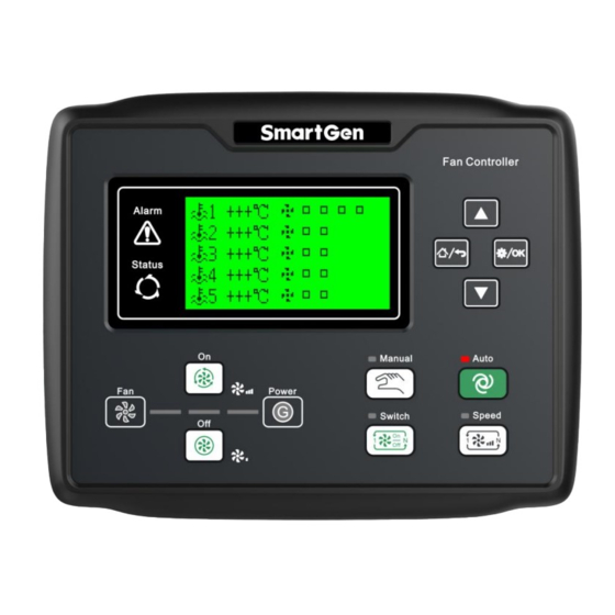
1 OVERVIEW HFC6100LT Fan Controller can be used for automatic control of 5 groups of fans, and can control its start/stop and PWN output function according to the selected temperature sensor. It has the function of balancing the running time of fan. This controller integrates digital, intelligent and network technologies and is able to work in the temperature range (-40°C~+70°C). -
Page 5: Specification
186mm x 141mm Working Condition Temperature: (-40~+70)ºC Relative Humidity: (20~93)%RH Storage Condition Temperature: (-40~+80)ºC Front panel: IP65, when waterproof gasket ring inserted between Protection Level panel and housing. Rear panel:IP20 Weight 0.6kg HFC6100LT Fan Controller User Manual Page 5 of 24... -
Page 6: Operation
In manual switch mode, light off after it is illuminated for 1s when pressing the switch key. Fan Speed In manual speed mode, light off after it is illuminated for 1s when pressing the speed key. HFC6100LT Fan Controller User Manual Page 6 of 24... -
Page 7: Keys Function Dscription
Screen scroll; Page Down/Decrease Down cursor and decrease value in parameter setting. Return to homepage when in main interface; Homepage/Return Return to previous interface when pressing this key in parameters setting interface. HFC6100LT Fan Controller User Manual Page 7 of 24... -
Page 8: Fan Controll Mode
NOTE: When balanced running time enables and meets the start condition, the fun with shortest running time will output; when meets the stop condition, the fun with longest running time will shut down. PWM1 will automatically output corresponding duty ratio according to the set PWM output curve. HFC6100LT Fan Controller User Manual Page 8 of 24... -
Page 9: One Group Of Fans Controlled By Two Groups Of Sensors
Select the corresponding speed output channel (PWM) by pressing . When select PWM1 channel, press to speed up (1#PWM output duty ratio increases), press to speed down (1#PWM output duty ratio decreases). HFC6100LT Fan Controller User Manual Page 9 of 24... -
Page 10: Protection
When the controller detects that the #1~12 fan faults input, or the input 13 #1~12 Fan Faults port set fans running input and when fans output, when fans running do not input, the controller will send corresponding alarm signal. HFC6100LT Fan Controller User Manual Page 10 of 24... -
Page 11: Connections
6 CONNECTIONS The rear panel of HFC6100LT is as below: Fig.3 – Controller Rear Panel Drawing Table 6 – Terminal Connection Description Function Cable Size Remark DC input B- 1.5mm Connect to negative of battery Connect to positive of battery. - Page 12 Connect to temp. sensor 4. 48 Sensor 5 Input 1.0mm Connect to temp. sensor 5. Sensor common port 49 Sensor Common Port The controller interior has been connected to power input B-. HFC6100LT Fan Controller User Manual Page 12 of 24...
-
Page 13: Parameter Range And Definition
2 groups of fan controlled. Groups Sensor Custom Custom temperature sensor curve Resistance Curve Temperature). Sensor 2 Fan Control Custom fan control curve (X: Temperature Y: Number of fan Curve output) HFC6100LT Fan Controller User Manual Page 13 of 24... - Page 14 Sensor 5 High Alarm send high temperature signal. When the (0-300)℃ Threshold Value setting value is equal to 300, it will not send the signal. HFC6100LT Fan Controller User Manual Page 14 of 24...
- Page 15 Refer to Table 9 Output 11Type (0-1) 0: Normally open; 1: Normally close. Factory default: 5 groups of fan control Aux. Output 12 Setting (0-25) output. Refer to Table 9 HFC6100LT Fan Controller User Manual Page 15 of 24...
- Page 16 Aux. Input 9 Active (0-1) Factory default: closed Aux. Input 9 Delay (0-20.0)s Aux. Input 10 Setting (0-35) Factory default: 10#fan running input. Aux. Input 10 Active (0-1) Factory default: closed HFC6100LT Fan Controller User Manual Page 16 of 24...
- Page 17 The corresponding temperature value of (0-300)°C Temp. PWM1 mini. duty ratio. 1#PWM Output (0-100) % The PWM1 maximum duty ratio. Maximum 1#PWM Output Max. The corresponding temperature value of (0-300)°C Temp. PWM1 max. duty ratio. HFC6100LT Fan Controller User Manual Page 17 of 24...
- Page 18 Fan Running Detection When detects delay is 0s, fun operation Delay input is not detected. In auto mode, after the unit operation Fan Off Delay (0-3600)s input inactive, output disconnected delay time. HFC6100LT Fan Controller User Manual Page 18 of 24...
-
Page 19: Sensor Selection
Open Circuit Alarm when sensor 3 is disconnected. Alarm Sensor 3 High Alarm Alarm when temperature of sensor 3 is high. Sensor Open Circuit Alarm when sensor 4 is disconnected. Alarm HFC6100LT Fan Controller User Manual Page 19 of 24... -
Page 20: Digital Input 1-18
9# Fan Fault Input 10# Fan Fault Input 11# Fan Fault Input 12# Fan Fault Input Simulate Manual An external key can be connected to simulate the panel key to Input be pressed. HFC6100LT Fan Controller User Manual Page 20 of 24... -
Page 21: Parameter Setting
Press to display digital input/output ports status. c) Press to display the start interface. 8.5 FAN RUNNING TIME The fan running time can be viewed through this item. HFC6100LT Fan Controller User Manual Page 21 of 24... -
Page 22: Commissioning
PWM output duty ratio. — Set controller to auto mode, automaticlly control fan on/off according to the sensor temperature. — If there are any other questions, please contact SmartGen’s service. 10 TYPICAL APPLICATION Fig.4 - HFC6110LT Typical Application Diagram... -
Page 23: Installation
RC loop (when expansion relay coil links AC), in case controller or other equipment are interfered. — Dielectric strength test: when the controller has been installed in the control panel, during the test please disconnect all the terminals, in case high voltage damages the controller. HFC6100LT Fan Controller User Manual Page 23 of 24... -
Page 24: Troubleshooting
Check if COM port is correct; RS485 Communication Failure Check if A and B of RS485 is connected reversely; Check if PC COM port is damaged; 120Ω resistance between RS485 and AB is Recommended. _______________________________ HFC6100LT Fan Controller User Manual Page 24 of 24...
Need help?
Do you have a question about the HFC6100LT and is the answer not in the manual?
Questions and answers