
Related Manuals for GRASS VALLEY Ignite SDC Series


Summary of Contents for GRASS VALLEY Ignite SDC Series
- Page 1 Ignite LIVE PRODUCTION CONTROL SYSTEM SDC/HDC Robotic Camera Instruction Manual 071849200 SEPTEMBER 2006...
- Page 2 Affiliate with the N.V. KEMA in The Netherlands CERTIFICATE Certificate Number: 510040.001 The Quality System of: Grass Valley, Inc. 400 Providence Mine Road 15655 SW Greystone Ct. 10 Presidential Way Nevada City, CA 95945 Beaverton, OR 97006 Floor, Suite 300...
- Page 3 Ignite LIVE PRODUCTION CONTROL SYSTEM SDC/HDC Robotic Camera Instruction Manual 071849200 SEPTEMBER 2006...
- Page 4 +33 1 45 29 73 00 Germany, Europe +49 6150 104 782 +49 6150 104 223 Copyright © Grass Valley. All rights reserved. This product may be covered by one or more U.S. and foreign patents. Grass Valley Web Site www.thomsongrassvalley.com web site offers the following: —...
-
Page 5: Table Of Contents
Contents Contents Preface ..............About This Manual . - Page 6 Contents Section 3 — Operation ..........Operating Procedure .
- Page 7 Contents Iris, Shutter, Gain Settings Overview ....... . . Color Settings ........... . . G/L Adjustment Settings .
- Page 8 Contents Ignite SDC/HDC Robotic Camera Instruction Manual...
-
Page 9: Preface
Preface About This Manual This manual is for technical personnel responsible for installation, setup, and operation of an Ignite SDC/HDC robotic camera. This manual is for camera models SDC-3100P/-3110P/-3100N/-3110N and HDC-3200/-3210/-3300/-3310. Standard Documentation The standard Ignite SDC/HDC robotic camera documentation set com- prises: •... - Page 10 Preface Ignite SDC/HDC Robotic Camera Instruction Manual...
-
Page 11: Safety Summary
Safety Summary Read and follow the important safety information below, noting especially those instructions related to risk of fire, electric shock or injury to persons. Additional specific warnings not listed here may be found throughout the manual. WARNING Any instructions in this manual that require opening the equipment cover or enclosure are for use by qualified service personnel only. -
Page 12: Symbols On The Product
Safety Summary Symbols on the Product The following symbols may appear on the product: Indicates that dangerous high voltage is present within the equipment enclosure that may be of sufficient magnitude to constitute a risk of electric shock. Indicates that user, operator or service technician should refer to product manual(s) for important operating, maintenance, or service instructions. -
Page 13: Cautions
Safety Summary — Do not operate this Operate only with covers and enclosure panels in place product when covers or enclosure panels are removed. — Do not operate in wet or damp conditions. Use only in dry environment — Do not operate this product in an Use only in non-explosive environment explosive atmosphere. - Page 14 Safety Summary — Protect the precision made lens by Cap the lens when camera is not in use placing the lens cap over the lens when the camera is not in use. If the lens is not installed, protect the surface of the prism by placing the body cap into the lens mount hole.
-
Page 15: Regulatory Notices
Changes or modifications not expressly approved by Grass Valley Group can affect emission compliance and could void the user’s authority to operate this equipment. -
Page 16: Canadian Certified Power Cords
Regulatory Notices Canadian Certified Power Cords Canadian approval includes the products and power cords appropriate for use in the North America power network. All other power cords supplied are approved for the country of use. Canadian Certified AC Adapter Canadian approval includes the AC adapters appropriate for use in the North America power network. -
Page 17: Section 1 - Overview
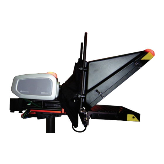
Section Overview Introduction The Ignite SDC/HDC robotic camera (Figure 1) is a compact, fully-inte- grated, remote-control camera designed for worldwide Broadcast and high-end ProAV applications. Figure 1. Ignite SDC/HDC Robotic Camera Both SDC and HDC models feature internet protocol (IP) control, con- verged pan/tilt/focus/zoom operation for seamless on-air movements, fast pan and tilt speed (90°/s maximum), 300 location presets, 600 seconds of movement recalls, super-quiet operation <30 dBm @ 1 m, integrated... -
Page 18: Hardware Description
To order SDC/HDC Robotic Camera hardware and accessories listed in this manual, refer to Contacting Grass Valley on page SDC/HDC robotic cameras contain a camera block with integrated tally light, mounted on a robotic pan/tilt head and pedestal mount. HDC models come with either premium or standard lens. -
Page 19: Ethernet Hub
Optional Mounting Hardware Ethernet Hub An Ethernet hub, (10/100/1000 Base TX, auto-sensing) is required to connect up to 16 Ignite SDC/HDC robotic cameras to a JSC-2300 SHOT Director robotics/camera controller. Optional Mounting Hardware The following optional mounting hardware is recommended for use with Ignite SDC/HDC robotic cameras. -
Page 20: Robotic Camera And Shot Director
Section 1 — Overview The robotic head processes the pan and tilt inputs and moves the camera to the commanded location. It passes zoom and focus commands to the lens assembly. It also provides a communication path between the camera head and SHOT Director (for configuration and status monitoring), and pro- vides 12 V dc to power the camera block. -
Page 21: Robotic Camera And Ignite Automated Production Control System
Functional Description Robotic Camera and Ignite Automated Production Control System The SDC/HDC robotic camera was designed to operate as an integrated part of an Ignite automated production control system. (Figure The Ignite system provides TCP/IP automation control to the JSC-2300 SHOT Director robotics/camera controller, video switcher, tally controller, and optional Script Viewer devices. - Page 22 Section 1 — Overview Ignite SDC/HDC Robotic Camera Instruction Manual...
-
Page 23: Section 2 - Installation
Immediately report any missing or damaged items to the carrier and to your Grass Valley Service Representative (See Contacting Grass Valley on page Keep all manuals supplied with your equipment. You will need them to complete the installation procedures. -
Page 24: Robotic Pan/Tilt Head Assembly
Section 2 — Installation Robotic Pan/Tilt Head Assembly Note Ignite SDC/HDC robotic cameras are suitable for inverted mounting. 1. Check the selected camera location to ensure that there is enough clearance (Figure 5) for the fully assembled camera, prompter, and cables to pan and tilt without obstruction. - Page 25 Installation Procedures CAUTION Ensure that the selected mounting surface and hardware can safely support the weight of a fully assembled unit (approximately 55 lbs (29.95 kg)). 3. If ceiling/inverted mounting is required: • Remove the L-bracket, rotate it 180 degrees, then re-attach it to the robotic pan/tilt head.
- Page 26 Section 2 — Installation Figure 7. Robotic Pan/Tilt Head Mounting Ceiling Mount Safety Wire Safety Wire Tripod Mount L-bracket must be inverted L-bracket must be inverted Tripod adapter plate Tripod Ignite SDC/HDC Robotic Camera Instruction Manual...
-
Page 27: Prompter Adapter Plate (Optional)
Installation Procedures Prompter Adapter Plate (Optional) Note The prompter assembly is supported by a mounting plate that sits beneath the camera assembly. 1. Attach camera adapter plate to prompter adapter plate (Figure Figure 8. Prompter and Camera Adapter Plates Camera adapter plate Mounting... -
Page 28: Camera/Lens Assembly
Section 2 — Installation Camera/Lens Assembly 1. Ensure camera/lens assembly is oriented toward the front of the pan/ tilt head assembly. 2. Mount the camera/lens assembly to the camera adapter plate (if installing prompter), or directly to the robotic pan/tilt head assembly L-bracket with two 3/8-16 x 0.5”... -
Page 29: Prompter (Optional)
Installation Procedures Prompter (Optional) 1. Slide extrusion slots onto mounting plate rods and rotate rods to tighten (Figure 10). Mounting plate rods slide into the back of the extrusion where two slots provide alternative vertical positions for the prompter. The rods attach to the extrusion using a T-bolt that is tightened by turning the rod. -
Page 30: System Interconnection
Section 2 — Installation System Interconnection Figure 12 and the following steps to connect the camera, lens, pan/tilt head, and prompter assemblies to a JSC 2300 SHOT Director controller and an Ignite system. If you are not connecting to an Ignite system use the fol- lowing steps and Figure Figure 12. -
Page 31: Robotic Pan/Tilt Head
System Interconnection Figure 13. Interconnect (without Iignite System) Diagram SDC/HDC ROBOTIC CAMERA SHOT RED TALLY OPTICAL SENSOR DIRECTOR PROMPTER SHOT SUBNET CAMERA PAN/TILT LENS DIRECTOR HEAD BLOCK IRIS IP CONTROL IP CONTROL CTRL/PWR ZOOM/FOCUS ZOOM/FOCUS 48 VDC PWR SUPPLY FACILITY PROVIDED EQUIPMENT VIDEO VIDEO... -
Page 32: Prompter (Optional)
Section 2 — Installation 2. Connect an SDI video cable (not supplied) from the camera block to a studio monitor or video switcher (with studio monitor output). 3. If using a video switcher, connect genlock to the camera block. 4. Connect the Iris control cable from the lens assembly to the camera block. -
Page 33: Section 3 - Operation
Section Operation Operating Procedure 1. Turn on all equipment power. WARNING Ensure personnel and obstacles are clear of the camera during power-up. The robotic head will automatically rotate to the preset zero degree pan and tilt location. Note The camera robotics may make some noise for the first few hours of opera- tion. - Page 34 Section 3 — Operation c. Black balance adjustment. This adjustment is needed when the camera is used for the first time, after being unused for a long time, or when the ambient tem- perature changes significantly (i.e. seasonal changes). Note After adjusting the black balance, re-adjustment is not needed under the same conditions.
- Page 35 Operating Procedure Note The HDC camera accepts SD and HD synchronizing signals. HD synchro- nizing signals may require different test equipment and may display differ- ently than signals shown in Figure • Using a two-channel oscilloscope, observe the gen-lock input and camera video output waveforms.
- Page 36 Section 3 — Operation Ignite SDC/HDC Robotic Camera Instruction Manual...
-
Page 37: Section 4 - Service
(Table 2). If questions or problems still exist after troubleshooting, please contact your authorized Grass Valley reseller or contact Grass Valley Customer Support directly. (See Contacting Grass Valley on page 4.). Table 2. Troubleshooting (Problem/Cause/Solution) Matrix... - Page 38 Section 4 — Service Table 2. Troubleshooting (Problem/Cause/Solution) Matrix Problem Cause Solution SHOT Director or hub communication Ensure all devices are powered. failure. Check CAT5 cable between SHOT No traffic indicated on the network Director and hub. hub front panel LEDs. Use crossover cable between SHOT Director and pan/tilt head (no hub).
- Page 39 Troubleshooting Table 2. Troubleshooting (Problem/Cause/Solution) Matrix Problem Cause Solution Poor quality video Check video cable connected to back of camera block. Ensure DB9 connector at pan/tilt head is connected and that the zoom/focus cable is connected to the lens assem- bly.
- Page 40 Section 4 — Service Ignite SDC/HDC Robotic Camera Instruction Manual...
-
Page 41: Appendix A - Sd (Ntsc) Camera Block
Appendix SD (NTSC) Camera Block Controls and Indicators SD (NTSC) camera controls and indicators are shown in Figure 16 described in Table Figure 16. SD Camera Controls and Indicators FRONT REAR ZOOM/FOCUS Table 3. SD Camera Controls and Indicators Item Name Description Lens mount 2/3”... -
Page 42: Menu Selections
Appendix A — SD (NTSC) Camera Block Table 3. SD Camera Controls and Indicators Item Name Description SDI OUT 1 and 2 SDI video outputs (SDI Option card) When the camera is in shooting mode (menu not displayed), the color bar and shooting conditions are alternately indicated by pressing the switch. -
Page 43: Fluorescent Mode
Menu Selections Fluorescent mode Suited to indoor shooting under fluorescent lighting. Settings can be changed using a simple menu. Outdoor mode Suited to outdoor shooting. Settings can be changed using a simple menu. User mode Settings can be changed using a detail menu. Setting by Camera 1. -
Page 44: Menu Item Setting
Appendix A — SD (NTSC) Camera Block Menu Item Setting Each of the four use modes of the camera has a main menu (example shown Figure 18). Figure 18. Main Menu - Halogen, Fluorescent, Outdoor Mode Use mode Blinking • Each item of the main menu has a submenu, which consists of several settings. -
Page 45: Submenus Overview
Menu Selections Submenus Overview The following submenus are for Halogen Mode, Fluorescent Mode, and Outdoor Mode on the NTSC version of the SD camera. User Mode Submenus Overview on For User Mode submenus, refer to page Brightness Setting Figure 19. Brightness Setting Submenu Brightness Settings Table 4. -
Page 46: Color Setting
Appendix A — SD (NTSC) Camera Block Brightness Settings Table 4. Selection Description Manual setting is possible only when the Auto Gain Up setting is “OFF”. 0 dB: 0 dB should be selected in normal cases. 1 dB - 30 dB: Use this range if sufficient video output cannot be obtained even when the lens iris is opened in shooting dark scenes. -
Page 47: G/L, Color Bar Setting
Menu Selections G/L, Color Bar Setting Figure 21. GL, Color Bar Setting Submenu Table 6. Color Bar Settings Selection Description (-206 to +49) Horizontal phase can be adjusted when a genlock signal is H Phase supplied. (1, 2, 3, 4) Coarse adjustment of sub carrier phase can be made when a SC Coarse genlock signal is supplied. -
Page 48: Other Settings Overview
Appendix A — SD (NTSC) Camera Block Table 7. Sharpness (DTL) Settings Selection Description Clean DNR (OFF, Low, High) This enables the clean DNR effect to be selected. (OFF, Low, High) Flesh noise is suppressed in two steps when the Level Flesh Noise Sup. - Page 49 Menu Selections Table 8. Other Settings Selection Description (60.34 Hz to 15.75 kHz) This setting is possible only when the Shutter Speed setting is at S/Scan. Horizontal bar noise can be reduced by synchro-scan adjustment in shoot- ing workstation scenes, for example. *For luminance settings at each shutter speed and synchro-scan shutter speed, refer to the following table.
-
Page 50: User Mode Submenus Overview
Appendix A — SD (NTSC) Camera Block User Mode Submenus Overview Iris, Shutter, Gain Settings Overview Figure 24. Iris, Shutter, Gain Settings Submenu Table 9. Iris, Shutter, Gain Settings Selection Description (-50 to +50) Convergence level of AUTO IRIS, AUTO GAIN UP, ELC can be Picture Level adjusted. - Page 51 Menu Selections Table 9. Iris, Shutter, Gain Settings Selection Description This setting is possible only when Step or Synchro Scan is selected in Shutter Mode setting. When “Step” has been selected as the Shutter Mode setting: OFF: Electronic shutter is turned off. 1/100, 1/250, 1/500, 1/1000, 1/2000, 1/4000, 1/10000: Electronic shutter operates at one of these speeds as selected.
-
Page 52: Color Settings
Appendix A — SD (NTSC) Camera Block Color Settings Figure 25. Color Settings Submenu Table 10. Color Settings Selection Description Chroma Level (-3 to +3) Chroma Level can be decreased or increased to three levels. ATW: The white balance is automatically adjusted to the optimum position. AWC A, AWC B: Once the white balance is adjusted with the ITEM/AWC switch on the back of the camera, it is no longer necessary to set the white balance again if you simply select AWC A or AWC B, provided that the... -
Page 53: G/L, Color Bar Settings
Menu Selections G/L, Color Bar Settings Figure 26. G/L Color Bar Setting Submenu Table 11. G/L Color Bar Settings Selection Description (-206 to +49) Horizontal phase can be adjusted when a genlock signal is H Phase supplied. (1, 2, 3, 4) Coarse adjustment of sub carrier phase can be made when a SC Coarse genlock signal is supplied. -
Page 54: Color Matrix Settings
Appendix A — SD (NTSC) Camera Block Table 12. Detail Settings Selection Description H Detail Level L (0 to H-1) V Detail Level L (0 to H-1) (1 to 5) A contour correction band can be set with the Detail setting at High Detail Band or Low. -
Page 55: Other Settings
Menu Selections Table 13. Color matrix Settings Selection Description YI Phase Varies the hue of the yellow. YI_G Gain Increases or decreases the intermediate color between yellow and green. YI_G Phase Varies the hue of the intermediate color between yellow and green. G Gain Increases or decreases the green. -
Page 56: To Return To Initial Settings
Appendix A — SD (NTSC) Camera Block Table 14. Other Settings Selection Description Aspect Ratio Aspect ratio can be selected from 16:9 or 4:3. OFF: Select this setting to stop the fan when its operating sound is found to be bothersome in a studio or other such environment. Fan SW Auto: The temperature is detected automatically, and the fan starts operat- ing when the temperature exceeds approx. - Page 57 Menu Selections Figure 32. Data Unchanged Screen Table 15. Factory preset values for Halogen Mode, Fluorescent Mode, and Outdoor Mode Halogen mode Fluorescent mode Outdoor mode Item Picture Level ±0 ±0 ±0 Light PEAK/AVG Light Area Top cut Top cut Top cut Auto ND (ELC) Brightness Set...
- Page 58 Appendix A — SD (NTSC) Camera Block Table 16. Factory preset values for User Mode Item User mode Picture Level ±0 Light PEAK/AVG Light Area Top cut Auto Iris Adjust Iris, Shutter, Gain Set Shutter Mode Step Step/Synchro Gain 0 dB AGC Max Gain Chroma Level White Bal...
- Page 59 Menu Selections Table 16. Factory preset values for User Mode Item User mode Gamma 0.45 Knee Point White Clip 110% Flare R Other Set 1 Flare G Flare B Black Stretch Clean DNR Field/Frame Field Baud Rate 9600 bps Component Y/Pr/Pb Other Set 2 Aspect Ratio...
-
Page 60: Specifications
Appendix A — SD (NTSC) Camera Block Specifications SD camera specifications are listed in Table Table 17. SD Camera Specifications Power Requirements 12 Vdc 15 W Optical System 2/3” Prism optical system, F1.4 Pickup Device 2/3” Interline wide CCD Total Pixels 1020 (H)x505 (V) (About 510000 pixels) Scanning System 525 lines, 60 fields, 30 flames... -
Page 61: Appendix B - Sd (Pal) Camera Block
Appendix SD (PAL) Camera Block Controls and Indicators SD (PAL) camera controls and indicators are shown in Figure 33 described in Table Figure 33. SD Camera Controls and Indicators FRONT REAR ZOOM/FOCUS Table 18. SD Camera Controls and Indicators Item Name Description Lens mount 2/3”... -
Page 62: Menu Selections
Appendix B — SD (PAL) Camera Block Table 18. SD Camera Controls and Indicators Item Name Description SDI OUT 1 and 2 SDI video outputs (SDI Option card) When the camera is in shooting mode (menu not displayed), the color bar and shooting conditions are alternately indicated by pressing the switch. -
Page 63: Outdoor Mode
Menu Selections Outdoor mode Suited to outdoor shooting. Settings can be changed using a simple menu. User mode Settings can be changed using a detail menu. Setting by Camera 1. Turn the camera on while keeping the MENU switch (Figure depressed. -
Page 64: Menu Item Setting
Appendix B — SD (PAL) Camera Block Menu Item Setting Each of the four use modes of the camera has a main menu (Figure 35). Figure 35. Main Menu - Halogen, Fluorescent, Outdoor Mode Use mode Blinking • Each item of the main menu has a submenu, which consists of several settings. -
Page 65: Brightness Setting
Menu Selections Brightness Setting Figure 36. Brightness Setting Submenu Brightness Settings Table 19. Selection Description (-50 to +50) Convergence level of AUTO IRIS/AUTO GAIN UP/ AUTO ND Iris Level (ELC) can be adjusted. (P50 to A50) The ratio of AUTO IRIS/AUTO GAIN up/AUTO ND (ELC) Iris PEAK/AVG detected peak to average can be adjusted within a predetermined range. -
Page 66: Color Setting
Appendix B — SD (PAL) Camera Block Color Setting Figure 37. Color Setting Submenu Table 20. Color Settings Selection Description (-3 to +3) Chroma Level can be decreased or increased to any of three lev- Chroma Level els each. (-3 to +3) Skin color can be decreased or increased to any of three levels Flesh Tone each. -
Page 67: Sharpness (Dtl) Setting Overview
Menu Selections Sharpness (DTL) Setting Overview Figure 39. Sharpness (DTL) Settings Submenu Table 22. Sharpness (DTL) Settings Selection Description (Normal, Super DTL) If contour correction is not sufficient at the Normal position when Detail Level setting is set to Low or High, select the Super DTL Select DTL position. -
Page 68: Other Settings Overview
Appendix B — SD (PAL) Camera Block Other Settings Overview Figure 40. Other Settings Submenu Table 23. Other Settings Selection Description Contrast (Gamma) (Low, Mid, High) Contrast can be adjusted to any of three levels. OFF: Electronic shutter is turned off. 1/120, 1/250, 1/500, 1/1000, 1/2000, 1/4000, 1/10000: Electronic shutter operates at one of these speeds as selected. -
Page 69: User Mode Submenus Overview
Menu Selections Table 23. Other Settings Selection Description This enables RGB, Y/Pr/Pb or Y/C to be selected as the component signals Signal Select which are to be output from the I/F REMOTE connector. Aspect Ratio Aspect ratio can be selected from 16:9 or 4:3. OFF: Select this setting to stop the fan when its operating sound is found to be bothersome in a studio or other such environment. - Page 70 Appendix B — SD (PAL) Camera Block Table 24. Iris, Shutter, Gain Settings Selection Description This setting is possible only when Step or Synchro Scan is selected in Shutter Mode setting. When “Step” has been selected as the Shutter Mode setting: OFF: Electronic shutter is turned off.
-
Page 71: Color Settings
Menu Selections Color Settings Figure 42. Color Settings Submenu Table 25. Color Settings Selection Description Chroma Level (-3 to +3) Chroma Level can be decreased or increased to three levels. ATW: The white balance is automatically adjusted to the optimum position. AWC A, AWC B: Once the white balance is adjusted with the ITEM/AWC switch on the back of the camera, it is no longer necessary to set the white balance again if you simply select AWC A or AWC B, provided that the... -
Page 72: G/L Adjustment Settings
Appendix B — SD (PAL) Camera Block G/L Adjustment Settings Figure 43. G/L Adjustment Setting Submenu Table 26. G/L Adjustment Settings Selection Description (-206 to +49) Horizontal phase can be adjusted when a genlock signal is H Phase supplied. (1, 2, 3, 4) Coarse adjustment of sub carrier phase can be made when a SC Coarse genlock signal is supplied. -
Page 73: Color Matrix Settings
Menu Selections Table 27. Detail Settings Selection Description (1 to 5) A contour correction band can be set with the Detail setting at High Detail Band or Low. The higher setting, the finer will be the detail. (1 to 10) Screen noise can be reduced with the Detail setting at High or Noise Suppress Low. -
Page 74: Other Settings
Appendix B — SD (PAL) Camera Block Table 28. Color matrix Settings Selection Description YI_G Phase Varies the hue of the intermediate color between yellow and green. G Gain Increases or decreases the green. G Phase Varies the hue of the green. G_Cy Gain Increases or decreases the intermediate color between green and cyan. -
Page 75: Initial Settings
Menu Selections Table 29. Other Settings Selection Description Aspect Ratio Aspect ratio can be selected from 16:9 or 4:3. OFF: Select this setting to stop the fan when its operating sound is found to be bothersome in a studio or other such environment. Fan SW Auto: The temperature is detected automatically, and the fan starts operat- ing when the temperature exceeds approx. - Page 76 Appendix B — SD (PAL) Camera Block Figure 49. Data Unchanged Screen Table 30. Factory preset values for Halogen Mode, Fluorescent Mode, and Outdoor Mode Halogen mode Fluorescent mode Outdoor mode Item Iris Level ±0 ±0 ±0 Iris PEAK/AVG iris Area Top cut Top cut Top cut...
- Page 77 Menu Selections Table 31. Factory preset values for User Mode Item User mode H Phase ±0 G/L, Color Bar Set SC Coarse SC Fine ±0 Detail High H Detail Level H V Detail Level H H Detail Level L Detail Set 1 V Detail Level L Detail Band Noise Suppress...
-
Page 78: Specifications
Appendix B — SD (PAL) Camera Block Specifications SD (PAL) camera specifications are listed in Table Table 32. SD Camera Specifications Power Requirements 12 Vdc 15.4 W Optical System 2/3” Prism optical system, F1.4 Pickup Device 2/3” Interline wide CCD Total Pixels 1008 (H)x591 (V) (About 540000 pixels) Scanning System... -
Page 79: Appendix C - Hd Camera Block
Appendix HD Camera Block Controls and Indicators HD camera controls and indicators are shown in Figure 50 and described Table Figure 50. HD Camera Controls and Indicators FRONT REAR Table 33. HD Camera Controls and Indicators Item Name Description Lens mount 2/3”... -
Page 80: Menu Selections
Appendix C — HD Camera Block Table 33. HD Camera Controls and Indicators Item Name Description G/L input connector For gen-lock with the camera, the external sync signal (black burst) or tri-level sync signal is supplied to this input connector. (G/L IN) HD SDI output connector SDI signal output. -
Page 81: Maintenance Menu
Menu Selections Figure 51. Top-Level USER Menu When the VIDEO MENU is selected: When the FILM MENU is selected: USER MENU USER MENU (FILM MENU) 1. MAINTENANCE 1. MAINTENANCE 2. SETTING 2. SETTING 3. CAMERA ID 3. CAMERA ID 4. FILE OPERATION 4. -
Page 82: Black Shading Menu
Appendix C — HD Camera Block Black Shading Menu The BLACK SHADING menu is shown in Figure 53. Menu selections are described in Table Figure 53. BLACK SHADING Menu BLACK SHADING DETECTION CORRECT(DIG) Table 34. BLACK SHADING Menu Selections Selection Description DETECTION [READY, ACTIVE] For automatically correcting the black shading. - Page 83 Menu Selections Table 35. PEDESTAL, GAMMA Menu Selections Selection Description M GAMMA [0.35 to 0.75 (DRS For adjusting the gamma characteristics. OFF), –10 to +10 (DRS ON)] R GAMMA [–15 to +15 (DRS For adjusting the gamma characteristics of the red in relation to the master gamma characteristics.
-
Page 84: Flare Menu
Appendix C — HD Camera Block Flare Menu The FLARE menu is shown in Figure 55. Menu selections are described in Table Figure 55. FLARE Menu FLARE R FLARE :000 G FLARE :000 B FLARE :000 FLARE Table 36. FLARE Menu Selections Selection Description R FLARE [000 to 100]... -
Page 85: Knee, White Clip Menu
Menu Selections Knee, White Clip Menu The KNEE, WHITE CLIP menu is shown in Figure 56. Menu selections are described in Table Figure 56. KNEE, WHITE CLIP Menu KNEE, WHITE CLIP (1/2) KNEE, WHITE CLIP (2/2) M KNEE POINT :95.00% KNEE :MANUAL R KNEE POINT... -
Page 86: R/B Gain Menu
Appendix C — HD Camera Block Table 37. KNEE, WHITE CLIP Menu Selections Selection Description R WHITE CLIP LVL For correcting the amount of red for the M WHITE CLIP LVL. [–15% to +15%] B WHITE CLIP LVL For correcting the amount of blue for the M WHITE CLIP LVL. [–15% to +15%] For selecting the knee operation mode. -
Page 87: Detail Menu
Menu Selections Detail Menu The DETAIL menu is shown in Figure 58. Menu selections are described in Table Figure 58. DETAIL Menu DETAIL (1/2) DETAIL (2/2) DETAIL SLIM DETAIL :OFF TOTAL DTL LEVEL :+00 DETAIL (+) :+00 H DTL LEVEL DETAIL (-) :+00 CRISP... -
Page 88: Skin Tone Detail Menu
Appendix C — HD Camera Block Skin Tone Detail Menu The SKIN TONE DETAIL menu is shown in Figure 59. Menu selections are described in Table Figure 59. SKIN TONE DETAIL Menu SKIN TONE DETAIL SKIN TONE DTL :OFF SKIN GET :OFF SKIN DTL CORING Y MAX... -
Page 89: Gain, Auto Iris Menu
Menu Selections Gain, Auto Iris Menu The GAIN, AUTO IRIS menu is shown in Figure 60. Menu selections are described in Table Figure 60. GAIN, AUTO IRIS Menu GAIN, AUTO IRIS LOW GAIN :0dB MID GAIN :9dB HIGH GAIN :18dB A. -
Page 90: Super Gain Menu
Appendix C — HD Camera Block Super Gain Menu The SUPER GAIN menu is shown in Figure 61. Menu selections are described in Table Figure 61. SUPER GAIN Menu S. GAIN (1/2) S. GAIN1 S. GAIN (2/2) S. GAIN1 MODE :S. -
Page 91: Frame Mode Menu
Menu Selections Frame Mode Menu The FRAME MODE menu is shown in Figure 62. Menu selections are described in Table Figure 62. FRAME MODE Menu FRAME MODE SCAN REVERSE :OFF FRAME RATE RANGE :60 - 6 FRAME RATE Table 43. FRAME MODE Menu Selections Selection Description SCAN REVERSE... -
Page 92: Matrix Menu
Appendix C — HD Camera Block Matrix Menu The MATRIX menu is shown in Figure 63. Menu selections are described Table Figure 63. MATRIX Menu MATRIX MATRIX TABLE MATRIX R - G :+00 MATRIX R - B :+00 MATRIX G - R :+00 MATRIX G - B :+00... -
Page 93: Color Correction Menu
Menu Selections Color Correction Menu The COLOR CORRECTION menu is shown in Figure 64. Menu selections are described in Table Figure 64. COLOR CORRECTION Menu COLOR CORRECTION (1/2) COLOR CORRECTION (2/2) PHASE PHASE R-Mg Mg-B B-Cy Cy-G G-Yl Yl-R Table 45. COLOR CORRECTION Menu Selections Selection Description R SAT/PHASE [–63 to +63]... -
Page 94: Mode Menu
Appendix C — HD Camera Block Mode Menu The MODE menu is shown in Figure 66. Menu selections are described in Table Figure 66. MODE Menu MODE (1/2) MODE (2/2) D5600K :OFF STATUS :OFF GAIN SELECT :LOW MENU ON BAR :OFF MENU SEL :VIDEO MENU... - Page 95 Menu Selections Table 46. MODE Menu Selections Selection Description FORMAT For selecting the video output format. The format is switched when the ENTER operation is performed. [720/60p, 59.94p, 50p, 1080/ 60i, 59.94i, 50i, 1080/30p, 29.97p, 25p, 24p, 23.98p] For turning the AWB/ABB operation displays ON or OFF. The status dis- plays are as follows.
-
Page 96: Shutter Menu
Appendix C — HD Camera Block Shutter Menu The SHUTTER menu is shown in Figure 67. Menu selections are described Table Figure 67. SHUTTER Menu SHUTTER SHUTTER MODE :OFF SHUTTER SPEED :1/100 SYNCHRO SCAN :60.32Hz Table 47. SHUTTER Menu Selections Selection Description For selecting the operation mode of the shutter. -
Page 97: Gen-Lock Menu
Menu Selections Gen-Lock Menu The GEN-LOCK menu is shown in Figure 68. Menu selections are described in Table Figure 68. GEN-LOCK Menu GEN-LOCK GEN-LOCK INPUT :BNC H PHASE-COARSE :+00 H PHASE-FINE :+000 SD HD PHASE CRS SD HD PHASE FINE :+00 Table 48. -
Page 98: Pix Defect Menu
Appendix C — HD Camera Block Pix Defect Menu The PIX DEFECT menu is shown in Figure 69. Menu selections are described in Table Figure 69. PIX DEFECT Menu PIX DEFECT AUTO DETECTION :READY Table 49. PIX DEFECT Menu Selections Selection Description When ACTIVE is selected, automatic defect compensation processing* is... -
Page 99: Protocol Menu
Menu Selections Protocol Menu The PROTOCOL menu is shown in Figure 70. Menu selections are described in Table CAUTION Changing the protocol to anything other than 4, will cause to camera block to lose communication with the pan/tilt head, SHOT Director, and Ignite system. If you lose communication, you must reset the protocol to 4 using the con- trols and indicators on the back of the camera block. -
Page 100: Camera Id Menu
Appendix C — HD Camera Block Camera ID Menu The CAMERA ID menu is shown in Figure 71. Menu selections are described in Table Figure 71. CAMERA ID Menu CAMERA ID ID :CAM1 Table 51. CAMERA ID Menu Selections Selection Description An ID of not more than 10 characters consisting of alphanumerics, sym- bols and spaces can be set for the camera. -
Page 101: File Operation Menu
Menu Selections File Operation Menu The FILE OPERATION menu is shown in Figure 72. Menu selections are described in Table Figure 72. FILE OPERATION Menu FILE OPERATION FILE OPERATION FILE OPERATION MODE :LOAD MODE :STORE MODE :STORE LOAD FROM :USER1 STORE TO :USER1 STORE TO... -
Page 102: Time Code Menu
Appendix C — HD Camera Block Time Code Menu The TIME CODE menu is shown in Figure 73. Menu selections are described in Table Note TIME CODE is displayed ONLY when FILM MENU has been set and either the 720/60p or 720/59.94p format has been selected. Figure 73. -
Page 103: Adjustments
Adjustments Adjustments Camera adjustments can be accomplished in one of two modes, shooting mode or menu mode. Shooting mode adjustments are accomplished by pressing rear panel switches while viewing a specific target object/scene. Menu mode adjustments are accomplished by accessing the USER menu, navigating to a desired submenu, then adjusting the value of a specific submenu item. - Page 104 Appendix C — HD Camera Block 2. Finely adjust the synchronizing signal input and video signal output phases by H PHASE-FINE. When using SD synchronizing signals: 1. Roughly adjust the synchronizing signal input and video signal output phases by SDHD PHASE-CRS (coarse). 2.
-
Page 105: Specifications
Specifications Specifications HD camera specifications are listed in Table Table 54. HD Camera Specifications Source Voltage 12 V dc Power Consumption 17 W Image Pickup Device 2/3” 1 million-pixel IT, CCDx3 System GBR image pickup system Resolving Optical System F1.4 prism Optical Filter ND;... - Page 106 Appendix C — HD Camera Block Ignite SDC/HDC Robotic Camera Instruction Manual...
-
Page 107: Appendix D - Robotic (Pan/Tilt Head)
Appendix Robotic (Pan/Tilt Head) Controls and Indicators Robotic pan/tilt head controls and indicators are shown in Figure 74 described in Table Figure 74. Robotic Pan/Tilt Head Controls and Indicators FRONT REAR Table 55. Robotic Pan/Tilt Head Controls and Indicators Item Name Description Zero degree tilt Used to orient the pan/tilt head in the desired direction prior to mounting. -
Page 108: Default And Recommended Camera Id And Ip Addresses
Appendix D — Robotic (Pan/Tilt Head) Table 55. Robotic Pan/Tilt Head Controls and Indicators Item Name Description Camera control cable provides serial control and 12 V dc power from the pan/ DB15 connector tilt head to the camera block. DB9 connector Zoom/focus to lens 8”... -
Page 109: Setting Soft Stops
Setting Soft Stops Setting Soft Stops Soft stops are software adjustable electrical limits for pan and tilt rotation. • The default soft stops for both pan and tilt are ± 178º. • If you install a prompter, you must set the tilt soft stops to ± 30º. •... - Page 110 Appendix D — Robotic (Pan/Tilt Head) Ignite SDC/HDC Robotic Camera Instruction Manual...
-
Page 111: Glossary
Glossary Clip A threshold level adjustment to which the keying attribute (luminance, chrominance) is Aspect compared for generating the internal key The horizontal and vertical display dimen- control signal. Clip, in conjunction with gain, sion ratio of a picture; i.e., the width divided sets the switching point between the back- by the height (usually expressed as x:y). - Page 112 Glossary Frame IP (Internet Protocol) One complete scan of a video image. For in- A data-oriented protocol used for communi- terlace video, alternate lines are scanned so a cating data across a packet-switched inter- frame containing all the picture information network.
- Page 113 Glossary ProAv Professional Audio/Video production. MAC (Media Access Control) A unique identifier (address) attached to most forms of networking equipment. On broadcast networks such as Ethernet, the MAC address allows each host to be unique- ly identified and allows frames to be marked for specific hosts.
- Page 114 Glossary S/N (Signal to Noise) Ratio Sync The amount of desired signal as compared to (1) General term for a synchronizing signal undesired signal. A way of measuring how or signal component. Digital systems gener- good a picture or a sound will be. The higher ally employ an analog external timing refer- the ratio between the desired type of signal ence signal (such as color black or tri-level...
- Page 115 Glossary TTL (Through-the-Lens) Term used to describe a type of prompter. A TTL prompter mounts horizontally in front of the camera. A glass screen mounted 45° above the prompter reflects the script so that the announcer can read the text while look- ing at the camera behind the screen.
- Page 116 Glossary Ignite Glossary...
-
Page 117: Index
Index Index Phase BAR SEL Baud Rate 49, 55, 68, B-Cy SAT/PHASE Numerics Black Balance 60, 78, 8” pedestal mount Gamma Shading Menu STR. LEVEL Stretch Acceleration Brightness 45, 57, 65, Accuracy - Repeatability Additional Equipment (Required) Adjustments CAM ID AGC Max Gain 45, 51, 65, Amphenol circular connector... - Page 118 Index Phase Halogen Mode, Fluorescent Mode, and SAT/PHASE Outdoor Mode (tbl) User Mode (tbl) Cy_B Gain Phase 49, 56, 69, Cy-G SAT/PHASE FAQ database Field/Frame File Operation Menu fixing ring knob D5600K Flare Dark Detail Menu DB15 connector R/G/B DB9 connector Flesh Noise Sup.
- Page 119 Index Menu Robotic Pan/Tilt Head Mounting (fig) Grass Valley web site Interface connector (I/F) G-Yl SAT/PHASE Introduction Iris 41, 61, Area GAIN Level MODE DETAIL LEVEL PEAK/AVG Detail Level Shutter, Gain Detail Level H 50, 58, 69, Detail Level L...
- Page 120 Index WHITE CLIP LVL Maintenance Menu online documentation Manu Gain Up Operate indicator MATRIX Operation Camera ID and IP address Optical Filter System Option Card TABLE Optional Mounting Hardware Matrix Other Menu Documentation 57, 59, 76, Maximum Load Capacity Settings 48, 55, 68, Menu Other Set...
- Page 121 Index Protocol SCAN REVERSE Menu Scanning System (NTSC) Camera Block (PAL) Camera Block HD PHASE CRS PHASE HD PHASE FINE WIDTH SECOND Selectors Sensitivity Service Setting BLACK GAMMA by Camera FLARE Soft Stops Gain Sharpness (DTL) 47, 57, 67, GAMMA Shooting Mode Adjustments KNEE POINT KNEE SLOPE...
- Page 122 Index System Interconnection web site FAQ database Camera/Lens Assembly web site Grass Valley Interconnect Diagram (fig) web site software download Power Weight 60, 78, 105, Prompter (Optional) White Balance 46, 52, 60, 66, 71, Robotic Pan/Tilt Head Adjustment White Clip...
Need help?
Do you have a question about the Ignite SDC Series and is the answer not in the manual?
Questions and answers