Table of Contents
Advertisement
Advertisement
Table of Contents

Related Manuals for GRASS VALLEY LDK 4000 MKII


Summary of Contents for GRASS VALLEY LDK 4000 MKII
- Page 1 User’s Guide 3922 496 30781 March 2007 v1.0 LDK 4000 MKII HDTV camera system...
-
Page 2: Declaration Of Conformity
Copyright Copyright Grass Valley Nederland B.V. 2006. Copying of this document and giving it to others, and the use or communication of the contents thereof, are forbidden without express authority. Offenders are liable to the payment of damages. All rights are reserved in the event of the grant of a patent or the registration of a utility model or design. -
Page 3: Table Of Contents
LDK 4000 MKII User’s Guide Chapter 1 – Introduction Technology............1-1 1.1.1... - Page 4 LDK 4000 MKII User’s Guide Video acquisition modes..........5-6 Viewfinder preferences .
- Page 5 Specifications for LDK 4000 MKII ........
- Page 6 End-of-life product recycling Grass Valley’s innovation and excellence in product design also extends to the programs we’ve established to manage the recycling of our products. Grass Valley has developed a comprehensive end-of-life product take back program for recycle or disposal of end-of-life products.
-
Page 7: Important Information
LDK 4000 MKII User’s Guide Important information Read these instructions carefully and retain them for future reference. During installation and operation of this equipment, local building safety and fire protection standards must be observed. Before connecting the equipment to the power supply of the installation, verify the proper functioning of the protective earth lead. - Page 8 LDK 4000 MKII User’s Guide Warnings To prevent fire or shock hazard, do not expose the unit to rain or moisture. If the unit is in a wet or damp environment, a rain cover must be used to protect it for personal safety reasons (EN60065).
- Page 9 LDK 4000 MKII User’s Guide Triax cable systems Only connect a Triax cable from the same LDK camera family to the unit. Do not allow system earth currents to exceed 1.5A in the outer shield of the Triax cable or 0.2A in other cable shields.
- Page 10 LDK 4000 MKII User’s Guide viii Base Station earthing The rear of the unit has two separate screw terminals for protective earth (PE) and video earth (VE). These are normally connected by a metal strap. Metal strap The protective earth terminal is internally connected to the protective earth conductor of the power cable.
- Page 11 LDK 4000 MKII User’s Guide Precautions To ensure continual high performance from the camera take the following precautions into consideration: • Avoid very damp places. If the environment is wet or damp a rain cover must be used to protect the unit.
- Page 12 LDK 4000 MKII User’s Guide...
-
Page 13: Chapter 1 - Introduction
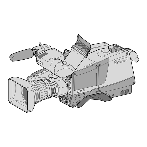
Chapter 1 Introduction 1.1 Technology The LDK 4000 MKII is a high definition, single-standard digital camera head using three 2/3-inch HD-DPM ™ sensors. The camera head can be combined with the TriaxHD adapter for a flexible camera that is equally at home in the studio or out on location. -
Page 14: Film-Like Characteristics
1.1.5 Different versions The LDK 4000 MKII camera head is available in two versions - 1080i or 720p. These versions support either 1080i or 720p HD formats in 50 Hz and 59.94 Hz. You decide when ordering which version you require. -
Page 15: Superxpander
LDK 4000 MKII User’s Guide | Introduction 1.1.7 SuperXPander The SuperXpander together with the optional 7-inch HD high resolution viewfinder turns the portable triax camera into a full-featured studio camera for studio and EFP situations. 1.2 Features • Ultimate flexibility with HD-DPM+ ™ CCD sensors, offering either native interlaced 1080i or true progressive 720p high definition broadcast formats (depending on version). - Page 16 LDK 4000 MKII User’s Guide | Introduction v1.0...
-
Page 17: Accessories
LDK 4000 MKII User’s Guide | Introduction 1.3 Accessories Xpander LDK 4489 SuperXpander LDK 4488 7” viewfinder support LDK 6517 HD/HS Triax Repeater LDK 4800 2” viewfinder HDTV LDK 5302/60 5” viewfinder HDTV LDK 5305/01 7” viewfinder HDTV High Brightness LDK 4020/20 Wide Angle adapter for 2"... - Page 18 LDK 4000 MKII User’s Guide | Introduction v1.0...
-
Page 19: Chapter 2 - Installation
If a unit is being returned to Grass Valley Nederland B.V. for servicing, try to use the containers and materials of the original packaging. Attach a tag indicating the type of service required, return address, model number, full serial number and the return number which will be supplied by your Grass Valley Nederland B.V. -
Page 20: Transport Case
LDK 4000 MKII User’s Guide | Installation 2.2 Transport case It is important to protect your camera against damage when transporting it. To do this, a transport case (LDK 5020/00) is optionally available for the camera, lens, viewfinder and some accessories. -
Page 21: Mounting A Lens
LDK 4000 MKII User’s Guide | Installation 2.3 Mounting a lens To attach a lens to the camera head proceed as follows: Ensure that the lens locking ring (1) is in the unlocked position - turned counterclockwise. Remove the dust protection cap (2). -
Page 22: 2-Inch Viewfinder
LDK 4000 MKII User’s Guide | Installation 2.4 2-inch viewfinder 2.4.1 Mounting viewfinder and microphone holder To mount the viewfinder LDK 5302/60 proceed as follows: Loosen locking ring (1) of viewfinder support bracket (2) at the front of the camera handle. -
Page 23: Positioning The Viewfinder
LDK 4000 MKII User’s Guide | Installation 2.4.2 Positioning the viewfinder The horizontal position of the viewfinder can be adjusted as follows to suit your requirements: Loosen the locking ring (1). (As seen from the rear of the camera, turning the locking ring counterclockwise moves it towards the handle.) -
Page 24: Viewfinder Accessories
LDK 4000 MKII User’s Guide | Installation 2.5 Viewfinder accessories 2.5.1 Wide angle eyepiece If you regularly use the viewfinder at a distance, for example, when you use the camera in the hand-held position, it is recommended that you fit the optionally available wide angle eyepiece (LDK 5390/00). -
Page 25: Mounting A Microphone
LDK 4000 MKII User’s Guide | Installation 2.6 Mounting a microphone To attach the optional microphone (AJ-MC700) to the camera proceed as follows: Open the microphone holder by unscrewing the knurled screw (2) of the microphone support bracket (1) on the viewfinder and open. -
Page 26: Tripod Adapter Plate
LDK 4000 MKII User’s Guide | Installation 2.7 Tripod adapter plate To mount the camera on a tripod, the tripod plate LDK 5031/10 must first be attached to the tripod. Follow the tripod manufacturer’s instructions to mount the wedge plate supplied with the tripod and the tripod adapter plate firmly onto the tripod. -
Page 27: Adjusting The Shoulder Pad
LDK 4000 MKII User’s Guide | Installation 2.8 Adjusting the shoulder pad To change the position the shoulder pad press and hold lever (1). The shoulder pad can now be moved backwards and forwards along the axis of the camera. Adjust the shoulder pad when all units have been mounted to get the best balanced shoulder position. -
Page 28: Attaching An Adapter
LDK 4000 MKII User’s Guide | Installation 2-10 2.9 Attaching an adapter The camera head is a multi-role camera head that can be used with various adapters. Caution Be extremely careful with the connectors between the camera head and the adapter. Do not allow the guide pins to damage the pins of the connector. -
Page 29: Chapter 3 - Configurations
LDK 4000 MKII User’s Guide | Configurations Chapter 3 Configurations 3.1 TriaxHD mode A camera head with the LDK 5860 TriaxHD adapter is connected to an LDK 4502 HD Base Station using a Triax cable. The maximum length of cable that can be used without significant degradation of the video signal is 1,200m (4,000 ft.) for a 14mm Triax cable. -
Page 30: Multiple Triaxhd Cameras With C2Ip Network
LDK 4000 MKII User’s Guide | Configurations 3.2 Multiple TriaxHD cameras with C2IP network The Base Stations are each connected to a network hub or router via an Ethernet cable (straight through, not cross-over). The OCP 400 operational control panels and, if required the MCP 400 Master Control Panel, are also connected to the Ethernet network via a hub or router. -
Page 31: Camera With Triaxhd Adapter And Superxpander
LDK 4000 MKII User’s Guide | Configurations 3.3 Camera with TriaxHD adapter and SuperXpander A camera head with the LDK 5860 TriaxHD adapter can be mounted in the LDK 4488 SuperXpander. This enables large box lenses to be used with the camera. A 7-inch HDTV viewfinder LDK 4020/20 can be mounted on the SuperXpander. -
Page 32: Local Mode
LDK 4000 MKII User’s Guide | Configurations 3.4 Local mode A camera head with the LDK 5860 TriaxHD adapter can be used in the local mode. The DC power supply is applied to the adapter. An OCP 400 operational control panel can be connected directly to the camera using the RS232 connection. -
Page 33: Triax Cable Lengths
LDK 4000 MKII User’s Guide | Configurations 3.5 Triax cable lengths The approximate maximum cable lengths between a Base Station and a camera are given in the table below. The signal degrades gradually when these lengths are exceeded. Reduce these lengths by 20% when a teleprompter signal is sent to the camera. - Page 34 LDK 4000 MKII User’s Guide | Configurations v1.0...
-
Page 35: Chapter 4 - Location Of Controls
LDK 4000 MKII User’s Guide | Location of controls Chapter 4 Location of controls 4.1 Camera head controls and connectors Figure 4-1. Camera connector location Viewfinder connector Lens HDMI Microphone RS232 connector connector connector connector v1.0... - Page 36 LDK 4000 MKII User’s Guide | Location of controls Figure 4-2. Camera head controls - front-left Cl ea r Cl ea r ND 1/ 4 St ar 4P ND 1/ 16 St ar 6P ND 1/ 64 cu s So ft Fo SW 2 Std.
- Page 37 LDK 4000 MKII User’s Guide | Location of controls Figure 4-3. Camera head controls Zoom control Tally indicator Tally indicator Cl ea r Cl ea r ND 1/ 4 St ar 4P ND 1/ 16 St ar 6P ND 1/ 64...
-
Page 38: Triaxhd Adapter Controls And Connectors
LDK 4000 MKII User’s Guide | Location of controls 4.2 TriaxHD adapter controls and connectors Figure 4-4. TriaxHD adapter controls Intercom routing switch Headset production vol. control selection Front Prod Rear Viewfinder display Headset volume Ext1 signal selection controls Ext2... - Page 39 LDK 4000 MKII User’s Guide | Location of controls Figure 4-5. TriaxHD adapter connector location Front Prod Rear Ext1 Ext2 Call Triax connector Mic 1 Front Rear Mic. Line Microphone 1 Mic. Line connector Ext. SD Ext. +48V Mic 2...
-
Page 40: Viewfinder Controls And Indicators
LDK 4000 MKII User’s Guide | Location of controls 4.3 Viewfinder controls and indicators Figure 4-1. Viewfinder controls Tally Zebra Option switch switch switch Tally Zebra Option Crisp Contr. Bright. Dioptre ring Crispening Contrast Brightness control control control Figure 4-2. Viewfinder markers and indicators... -
Page 41: Chapter 5 - Operating Instructions
LDK 4000 MKII User’s Guide | Operating instructions Chapter 5 Operating instructions 5.1 Using the camera Attach lens, viewfinder, microphone and any other accessories to the camera. Attach the triax cable or supply the adapter with power. 5.1.1 Switching on the power On the Base Station set the master power switch to the on position (I). -
Page 42: System Menu
LDK 4000 MKII User’s Guide | Operating instructions 5.2 System Menu The camera is operated via the viewfinder text display and the control system menu switches. The systems menu is viewed in the viewfinder and navigated by means of the Rotary control and the Select button which are both located at the front of the camera. -
Page 43: Finding Your Way
LDK 4000 MKII User’s Guide | Operating instructions Figure 5-2. Main menu Menu off exec Lens Video Install MENU: MAIN Files Security Diagnostics Service The MAIN menu screen shows five items. The name of the menu is shown below these. Four more items are hidden but become visible when you scroll down using the Rotary control. -
Page 44: Leaving The System Menu
LDK 4000 MKII User’s Guide | Operating instructions 5.2.3 Leaving the System Menu If you are deep within the menu structure, the recommended way of leaving the System menu If necessary move the cursor to the left column with the Select button. -
Page 45: Assigning Functions To Buttons
LDK 4000 MKII User’s Guide | Operating instructions 5.3 Assigning functions to buttons The camera head has three assignable buttons, two on the side panel (SW1) and (SW2), and one on the lower front panel (VTR start). The operation of the zoom control button and the VTR button on the lens can also be assigned. -
Page 46: Video Acquisition Modes
LDK 4000 MKII User’s Guide | Operating instructions Switch Assignments for Triax operation Zoom Switch on external signal 1 Switch on external signal 2 Zoom switch Momentary Alternating (latched) 5.4 Video acquisition modes In the INSTALL menu choose the video mode you wish to use for acquisition. The table below shows the output signals available for each model. -
Page 47: Viewfinder Preferences
LDK 4000 MKII User’s Guide | Operating instructions 5.5 Viewfinder preferences Set up the viewfinder according to your own preferences; adjust viewing parameters, select markers, message boxes and on-screen display times in the VF menu. Figure 5-5. Viewfinder controls Tally... -
Page 48: Viewfinder Markers
LDK 4000 MKII User’s Guide | Operating instructions Figure 5-6. Viewfinder markers and indicators Gain indicators Top indicators TAPE FOC+ BATT ND/RE Zoom indication Iris indicator Cadre marker Zebra pattern Centre marker Safe area Message box Non-standard Colour temp. 5.5.4 Viewfinder markers Go to the VF menu to select the markers you wish to see in the viewfinder. -
Page 49: Lens Preferences
LDK 4000 MKII User’s Guide | Operating instructions 5.6 Lens preferences When you fit a lens to the camera you may need to adjust the back focus. Refer to the lens manufacturer's instructions to find out how to do this. The LENS menu allows you to choose and, if necessary, adjust parameters to suit your lens type and your personal preferences. -
Page 50: Video Preferences
LDK 4000 MKII User’s Guide | Operating instructions 5-10 5.7 Video preferences The means used to control the camera depends on your work methods. A remote OCP can be used and a low user level can be selected to restrict the available camera functions. -
Page 51: Test Signal
LDK 4000 MKII User’s Guide | Operating instructions 5-11 Figure 5-7. Video control buttons Filter wheel switches Clear Clear Star 4P ND1/4 Star 6P ND1/16 Soft Focus ND1/64 SW 2 Std. File Standard file button Black stretch switch Colour temperature... -
Page 52: Gain Selection
LDK 4000 MKII User’s Guide | Operating instructions 5-12 5.7.3 Gain selection Depending on the available light levels it may be necessary to adjust the gain of the camera. The gain is selected via the Gain switch on the left-front side of the camera. -
Page 53: Colour Temperature Selection
LDK 4000 MKII User’s Guide | Operating instructions 5-13 The outer (bigger) filter switch has four positions: Position Filter Clear ND 1/4 filter (2 stops) ND 1/16 filter (4 stops) ND 1/64 filter (6 stops) The inner (smaller) filter switch also has four positions:... - Page 54 LDK 4000 MKII User’s Guide | Operating instructions 5-14 Selecting the colour temperature The up/down Colour temperature switch on the left-front side of the camera allows a choice between: Three preset colour temperatures: • 3200K (3.2K) - for studio lighting conditions •...
- Page 55 LDK 4000 MKII User’s Guide | Operating instructions 5-15 Auto-white balance If the reference colour temperatures do not match your lighting conditions carry out the auto- white procedure as follows: Figure 5-8. Auto white balance switches Std. SW 2 File Exp.
- Page 56 LDK 4000 MKII User’s Guide | Operating instructions 5-16 Press the White balance switch again to start the measurement procedure. A message indicating that the process is runnning appears. TAPE BATT ND/RE AWHITE: running ☞ Note If there is insufficient light, the ’Light level too low’ message appears in the viewfinder.
-
Page 57: Exposure Time
LDK 4000 MKII User’s Guide | Operating instructions 5-17 5.7.6 Exposure time The exposure time values of 1/200, 1/500 and 1/1000 of a second are used to capture fast moving objects so that these can be played back sharply in slow motion. The value selected depends on the speed of the moving object. -
Page 58: Shooting Screens
LDK 4000 MKII User’s Guide | Operating instructions 5-18 +10. To reduce flicker select the frequency closest to the frequency of the lights and then vary the lighting control in the INSTALL menu to obtain the best result. 5.7.7 Shooting screens Sometimes when shooting TVs or computer monitors a horizontal bar can be seen across these screens in the viewfinder. -
Page 59: Black Stretch
LDK 4000 MKII User’s Guide | Operating instructions 5-19 5.7.8 Black stretch The black stretch function changes the level of detail in the shadow areas of the picture without effecting the rest of the picture. Set the Black stretch switch to the On position to switch on the black stretch function. - Page 60 LDK 4000 MKII User’s Guide | Operating instructions 5-20 Press the Select button. The following appears in the viewfinder. TAPE BATT ND/RE ASKIN: window Point two small white boxes at the intended surface. Press the Select button to start the measurement procedure (the iris is set to Auto). The...
-
Page 61: Controls On The Triaxhd Adapter
LDK 4000 MKII User’s Guide | Operating instructions 5-21 5.8 Controls on the TriaxHD adapter Figure 5-1. Rear controls Intercom routing switch Headset production vol. control selection Front Prod Rear Viewfinder display Headset volume Ext1 signal selection controls Ext2 Call... -
Page 62: Selecting Monitoring Signals
LDK 4000 MKII User’s Guide | Operating instructions 5-22 5.8.2 Selecting monitoring signals Viewfinder display signal The viewfinder can display local or external video signals. Two switches determine the signal that is displayed in the viewfinder. The selection made with these switches also determines the VF connector output. -
Page 63: Using Audio
LDK 4000 MKII User’s Guide | Operating instructions 5-23 5.8.3 Using audio Two high quality audio channels are available in the Triax mode. Set the gain levels (-22 to -64 dB) for these channels in the AUDIO section of the INSTALL menu. A high-pass filter for each channel can also be switched on via this menu. -
Page 64: Intercom
LDK 4000 MKII User’s Guide | Operating instructions 5-24 5.8.4 Intercom Three intercom channels – production (Prod), programme sound (Prog) and engineering (Eng) – are sent from the Base Station to the camera operator's headset. The camera operator's intercom microphone signal is sent to the Base Station. Routing and volume controls for the intercom are on the back of the adapter. -
Page 65: Communication
LDK 4000 MKII User’s Guide | Operating instructions 5-25 5.8.5 Communication Call button Press this momentary button to send a signal to the control panels calling for attention. The ND/RE indicator in the 1.5-inch viewfinder shows when a call signal is sent or received. -
Page 66: Managing Files
LDK 4000 MKII User’s Guide | Operating instructions 5-26 5.9 Managing files You can have access to 15 different files. This number can be extended by using additional scene file camera cards. The Files menu is used to recall and store these files. There are two types of file: •... -
Page 67: Standard Files
LDK 4000 MKII User’s Guide | Operating instructions 5-27 5.9.3 Standard files The green STD button on the left-front side of the camera recalls the standard scene file. This file contains standard parameters for the picture performance. A standard operator's file can be recalled via the FILES menu. -
Page 68: Access And Security
LDK 4000 MKII User’s Guide | Operating instructions 5-28 5.11 Access and Security 5.11.1 Camera cards Three camera cards are delivered with each camera. These comprise of two user's cards and one owner's card. Figure 5-14. Camera cards Owner's Card... -
Page 69: Access Control
LDK 4000 MKII User’s Guide | Operating instructions 5-29 5.11.2 Access control The owner’s card or the PIN code is used to access special set-up and security features of the camera. Inserting the owner’s card into the associated camera always gives direct access to the Security menu (PIN code is not required). -
Page 70: Smart-Touch™ Option
LDK 4000 MKII User’s Guide | Operating instructions 5-30 5.12 Smart-Touch™ option Smart-Touch is an optional software module that gives immediate access to 14 pre-defined scene files. This library allows you to quickly set up the camera for different shooting conditions. -
Page 71: Chapter 6 - Menu Structure And Contents
LDK 4000 MKII User’s Guide | Menu structure and contents Chapter 6 Menu structure and contents 6.1 Menu structure The structure of the main menus and their submenus are shown on the following pages. The first column shows the user level (0 to 3). You only see menu functions whose user level is equal to or less than the user level set on your camera. -
Page 72: Viewfinder Menu Structure
LDK 4000 MKII User’s Guide | Menu structure and contents 6.1.2 Viewfinder menu structure 2 VF mon 2 VF Contour > VF Contour 0 Focus assist Level 3 Zebra > 0 Centre Cross 0 Audio Bar Zebra 0 Iris Indicator... -
Page 73: Lens Menu Structure
LDK 4000 MKII User’s Guide | Menu structure and contents 6.1.3 Lens menu structure Lens Type AutoIris Peak/Average AutoIris Setpoint Mom.Iris Setpoint Manufacturer Fuji RE Iris comp. Extended Iris > Min Iris Autoiris const > Max Iris Min Exp.Time 1/500... -
Page 74: Video Menu Structure
LDK 4000 MKII User’s Guide | Menu structure and contents 6.1.4 Video menu structure 2 Colour Filter 2 Contour Level 3 Contour > 3 Level 2 Soft Contour > 3 Source Select 3 Knee Contour 3 <more> > 3 vert cont 2 Skin >... -
Page 75: Install Menu Structure (Hdtriax)
LDK 4000 MKII User’s Guide | Menu structure and contents 6.1.5 Install menu structure (HDTriax) 3 Videomode 2 HD Aspect Ratio 16:9 0 Disable camera 0 IR receiver 0 Tally Handgrip (2”) 0 OnAir Lamp (7”) 1 Intercom > 1 SideTone 1 Audio >... -
Page 76: File Menu Structure
LDK 4000 MKII User’s Guide | Menu structure and contents 6.1.6 File menu structure 2 Store Scenefile > 2 file select 1 Recall Scenefile > 2 store 1 Store Oper.file > Recall Oper.file > 1 file select Attributes > 1 recall 2 Standard Files >... -
Page 77: Security Menu Structure
LDK 4000 MKII User’s Guide | Menu structure and contents 6.1.7 Security menu structure 2 Installed Level user3 2 Run Hours > days ago 0 PIN code 0000 set time > Hour 0 Customer Files > set date > Minute 0 Green Button >... -
Page 78: Menu Contents
LDK 4000 MKII User’s Guide | Menu structure and contents 6.2 Menu contents The number (0,1, 2 or 3) in the LEVEL column indicates the user level at which this item is visible in the menu; items with numbers higher than the user level that is set on the camera are not visible in the menu. - Page 79 LDK 4000 MKII User’s Guide | Menu structure and contents MENU VALUES DESCRIPTION LEVEL FILE Safe area On, Off The safe area indicates an area that represents 80% of the whole viewfinder picture area. Safe area type 16:9, 15:9, 14:9, 4:3 Set the aspect ratio of the safe area marker.
-
Page 80: Lens Menu Contents
LDK 4000 MKII User’s Guide | Menu structure and contents 6-10 6.2.2 Lens menu contents MENU VALUES DESCRIPTION LEVEL FILE Lens Type STD, WA Select a standard (STD) or wide angle (WA) type lens (affects white shading compensation). AutoIris On, Off... -
Page 81: Video Menu Contents
LDK 4000 MKII User’s Guide | Menu structure and contents 6-11 6.2.3 Video menu contents MENU VALUES DESCRIPTION LEVEL FILE Colour Filter 0..99 (50) This electronic colour filter varies the colour balance to obtain warmer or colder effects for the auto-white memory positions. It resets to 50 when the next automatic white balance process is carried out. - Page 82 LDK 4000 MKII User’s Guide | Menu structure and contents 6-12 MENU VALUES DESCRIPTION LEVEL FILE color2 Red 0..99 (50) Manual correction of skin gate (red color) for memory position 2. color2 Blue 0..99 (50) Manual correction of skin gate (blue color) for memory position 2.
-
Page 83: Install Menu Contents
LDK 4000 MKII User’s Guide | Menu structure and contents 6-13 6.2.4 Install menu contents MENU VALUES DESCRIPTION LEVEL FILE Video mode Available modes (1080i59) Select a video acquisition mode (Available modes depend on the camera version.) HD Aspect Ratio 16:9, Wide Select the aspect ratio. - Page 84 LDK 4000 MKII User’s Guide | Menu structure and contents 6-14 MENU VALUES DESCRIPTION LEVEL FILE Audio2 Gain -22dB, -28dB, -34dB, Set gain of Audio 2 channel for mic. input. -40dB, -46dB, -52dB, -58dB, -64dB Set gain of Audio 2 channel for line input.
-
Page 85: Files Menu Contents
LDK 4000 MKII User’s Guide | Menu structure and contents 6-15 6.2.5 Files menu contents MENU VALUES DESCRIPTION LEVEL FILE Store Scene file file select SCAM 1..4, SCARD 1..4, Select a memory-stored file (SCAM) or a card- stored file (SCARD). -
Page 86: Security Menu Contents
LDK 4000 MKII User’s Guide | Menu structure and contents 6-16 MENU VALUES DESCRIPTION LEVEL FILE DVW-xxx Exec For Sony camcorders. HL -xxx Exec For Ikegami camcorders. Standard Settings Exec Recalls camera standard settings. 6.2.6 Security menu contents MENU VALUES... -
Page 87: Diagnostics Menu Contents
LDK 4000 MKII User’s Guide | Menu structure and contents 6-17 6.2.7 Diagnostics menu contents MENU VALUES DESCRIPTION LEVEL FILE Adaptor Type Triax, DVCPRO, ... Displays value Sensor Type IT, ITW, FT, DPM Displays value Sensor Voltage Ok, NotOK Displays value... -
Page 88: Where To Find A Function
LDK 4000 MKII User’s Guide | Menu structure and contents 6-18 6.3 Where to find a function The following table contains an alphabetical list of the functions and points to their location in the menu structure. Function Subfunction Menu path... - Page 89 LDK 4000 MKII User’s Guide | Menu structure and contents 6-19 Function Subfunction Menu path INSTALL \ EXPOSURE \ CL. SCAN mode INSTALL \ EXPOSURE \ CL. SCAN units INSTALL \ EXPOSURE \ CL. SCAN value VIDEO \ Colour filter...
- Page 90 LDK 4000 MKII User’s Guide | Menu structure and contents 6-20 Function Subfunction Menu path VIDEO \ GAIN level green VIDEO \ GAIN level range VIDEO \ GAIN level red INSTALL \ GAIN PRESET presets VIDEO Gamma select VIDEO \ GAMMA...
- Page 91 LDK 4000 MKII User’s Guide | Menu structure and contents 6-21 Function Subfunction Menu path LENS manufacturer LENS type FILES \ STANDARD FILES Lighting conditions Marker shading style switch type VIDEO Matrix select LENS Momentary iris setpoint INSTALL Notch INSTALL...
- Page 92 LDK 4000 MKII User’s Guide | Menu structure and contents 6-22 Function Subfunction Menu path Rotary speed VIDEO Saturation FILES \ RECALL SCENEFILE Scene file recall switch FILES \ STORE SCENEFILE Scene file store switch Skin Contour VIDEO \ SKIN...
- Page 93 LDK 4000 MKII User’s Guide | Menu structure and contents 6-23 Function Subfunction Menu path Audio Bar switch VF \ VF CONTOUR Contour level VF \ VF CONTOUR Contour switch Centre cross switch Focus ind. switch Iris indicator switch Info time...
- Page 94 LDK 4000 MKII User’s Guide | Menu structure and contents 6-24 v1.0...
-
Page 95: Chapter 7 - Connectors
LDK 4000 MKII User’s Guide | Connectors Chapter 7 Connectors 7.1 Camera connectors Figure 7-1. Camera connector location Viewfinder connector Lens HDMI Microphone RS232 connector connector connector connector v1.0... -
Page 96: Viewfinder Connector
LDK 4000 MKII User’s Guide | Connectors 7.1.1 Viewfinder connector Figure 7-1. Camera viewfinder connector -80V n.c. vf video Pb vf ret INTN-D Pr vf ret vf ext video n.c. +batt vf video ret +batt SDA-D Pb vf SCL-D Pr vf... -
Page 97: Lens Connector
LDK 4000 MKII User’s Guide | Connectors 7.1.3 Lens connector Figure 7-3. Camera lens connector Ext. Video On/Off Lens Servo VTR Trigger Switch Range Extender -batt Zoom Follow Momentary Iris Focus follow* IrisControl Spare + batt * not standard on lens Iris Follow Hirose 12-pole female;... -
Page 98: Connectors On The Triaxhd Adapter
LDK 4000 MKII User’s Guide | Connectors 7.2 Connectors on the TriaxHD adapter Figure 7-2. TriaxHD adapter connector location Front Prod Rear Ext1 Ext2 Call Triax connector Mic 1 Front Rear Line Mic. Microphone 1 Mic. Line connector Ext. SD Ext. -
Page 99: Triax Connector
LDK 4000 MKII User’s Guide | Connectors 7.2.1 Triax connector Figure 7-6. Triax connector Centre pin: Power and signals Inner shield: Return Outer shield: Camera housing GND Various types of triax connector are available. Outer shield Centre pin Inner shield Panel view (X100) 7.2.2 Viewfinder / External video output connector... -
Page 100: Audio Microphone 1 Connector
LDK 4000 MKII User’s Guide | Connectors 7.2.5 Audio microphone 1 connector Figure 7-10. Audio microphone 1 connector Audio Screen Audio In Audio Return Microphone impedance > 200 ohm Phantom power +48V switchable Sensitivity range microphone: -64 to -22 dBu... -
Page 101: Dc Power Input Socket
LDK 4000 MKII User’s Guide | Connectors 7.2.8 DC power input socket Caution The input voltage must not exceed +17 Vdc. Figure 7-13. DC power input connector Ground Ground (internally bridged to pin 1) +11.5 Vdc . . . +17 Vdc (internally bridged to pin 4) +11.5 Vdc . -
Page 102: Teleprompter Output / Reference Input Connector
LDK 4000 MKII User’s Guide | Connectors 7.2.11 Teleprompter output / Reference input connector Figure 7-16. Teleprompter / Reference connector Teleprompter - Triax mode This socket supplies the 1Vpp teleprompter signal applied to the Base Station. Reference Input - Local mode This connector is used to genlock the camera to a 0.6 Vpp HD... -
Page 103: Auxiliary Connector
LDK 4000 MKII User’s Guide | Connectors 7.2.13 Auxiliary connector Figure 7-18. Auxiliary connector +5VL Spare On-air n.c. Private Data Camera to Base Station Ground Private Data Base Station to Camera Fischer 11-pole female; panel view Ground Panel part number (X109): 3922 040 02512... - Page 104 LDK 4000 MKII User’s Guide | Connectors 7-10 v1.0...
-
Page 105: Chapter 8 - Specifications
LDK 4000 MKII User’s Guide | Specifications Chapter 8 Specifications 8.1 Specifications for LDK 4000 MKII Item Value Power requirements supplied via adapter or local power Power consumption 60 W (camera head + TriaxHD adapter + viewfinder) Operating temperatures -20 to +45°C (-4 to +113°F) Storage temperatures -20 to +60°C (-4 to +140°F) -
Page 106: Specifications For Ldk 5860 Triaxhd Adapter
LDK 4000 MKII User’s Guide | Specifications Item Value White balance range 2500 - 20000 K Highlight compression Pivoting knee; Digital True Colour Knee Digital contrast Black stretch and black press Contour enhancement Full amplitude RGB, extended dynamic range circuit... -
Page 107: Dimensions
LDK 4000 MKII User’s Guide | Specifications 8.2.1 Dimensions Figure 8-1. Dimensions v1.0... - Page 108 LDK 4000 MKII User’s Guide | Specifications v1.0...
Need help?
Do you have a question about the LDK 4000 MKII and is the answer not in the manual?
Questions and answers