
Subscribe to Our Youtube Channel
Related Manuals for GRASS VALLEY LDK 3000+


Summary of Contents for GRASS VALLEY LDK 3000+
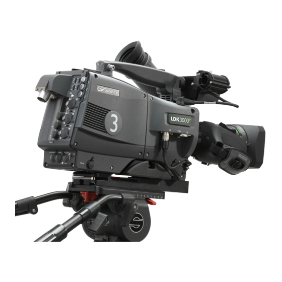
- Page 1 User’s Guide 3922 496 31881 October 2011 v1.0 LDK 3000+ High-Definition Camera Head...
-
Page 2: Declaration Of Conformity
Liable to technical alterations in the course of further development. Trademarks Grass Valley and Infinity are trademarks of Grass Valley, Inc. All other tradenames referenced are service marks, trademarks, or registered trademarks of their respective companies. -
Page 3: Table Of Contents
Table of contents Chapter 1 – Introduction Welcome............11 1.1.1 About this manual . - Page 4 Viewfinder preferences ..........34 4.4.1 Tally on/off switch .
- Page 5 Exposure time ............59 5.8.1 Selecting the exposure time .
- Page 6 Certificate of Recycling or a Certificate of Destruction, depending on the ultimate disposition of the product, can be sent to the requester. Grass Valley will be responsible for all costs associated with recycling and disposal, including freight, however you are responsible for the removal of the equipment from your facility and packing the equipment ready for pickup.
-
Page 7: Important Information
Important information Read these instructions carefully and retain them for future reference. Regularly check the Grass Valley website (www.grassvalley.com) for new updates of this and other user’s guides. During installation and operation of this equipment, local building safety and fire protection standards must be observed. - Page 8 Warnings To prevent fire or shock hazard, do not expose the unit to rain or moisture. If the unit is in a wet or damp environment, a rain cover must be used to protect it for personal safety reasons. To avoid electrical shock, do not remove covers or panels. Refer servicing to qualified personnel only.
- Page 9 Be careful when connecting and disconnecting Triax cables. – Do not mix units from different types of camera systems (HD with SD, Triax with digital Triax) – Do not connect Grass Valley camera systems with other manufacturer’s camera system parts. •...
- Page 10 Triax cable systems • Only connect a Triax cable from the same LDK camera family to the unit. • Do not allow system earth currents to exceed 1.5 A in the outer shield of the Triax cable or 0.2 A in other cable shields. •...
-
Page 11: Chapter 1 - Introduction
The LDK 3000+ has three 2/3-inch, 2.4 million pixels CMOS imagers specially developed for broadcast applications. Transmission of the full bandwidth HD signal is based on Grass Valley’s well proven, highly robust and reliable TriaxHD system. -
Page 12: Technology
Chapter 1 - Introduction 1.2 Technology 1.2.1 CMOS imagers The camera’s multi-format capability is realized with innovative 2/3-inch, 2.4 million pixel CMOS imagers specially developed for broadcast applications. Many unique features have been designed into these imagers such as DDS—Double Digital Sampling—and dual integrated A/D converters which create high-quality, razor-sharp pictures. -
Page 13: Transmission System
Chapter 1 - Introduction 1.3 Transmission system 1.3.1 LDK 5630 TriaxHD adapter TriaxHD, which is a further development of the Emmy Award winning Triax transmission system, makes the camera compatible with industry standard Triax cables. This allows the reuse of existing, reliable and valuable cable inventories. TriaxHD allows video transmission and remote control of cameras up to a distance of 1,200 m (3,900 ft) and beyond, using industry standard 14 mm (0.55 in) Triax cables. -
Page 14: Features
Chapter 1 - Introduction 1.4 Features • Economic high picture quality HD acquisition with three 2/3-inch, 2.4 million pixel CMOS imagers. • On-chip dual A/D conversion and 34-bit digital signal processing. • Unique DDS – Double Digital Sampling – for improved FPN performance. •... -
Page 15: List Of Accessories
Chapter 1 - Introduction 1.5 List of accessories System components LDK 4489 Xpander LDK 4488 SuperXpander LDK 6517 7-inch viewfinder support (for use with LDK 4021 7-inch viewfinder) LDK 4800 HD/HS Triax Repeater Viewfinders LDK 5302/60 2-inch HD viewfinder LDK 5307 7-inch LCD HD color viewfinder LDK 4021 7-inch CRT viewfinder (for use with SuperXpander) - Page 16 Chapter 1 - Introduction LDK 3000+ High-Definition Camera Head User’s Guide (v1.0)
-
Page 17: Chapter 2 - Installation
Chapter 2 - Installation Chapter 2 Installation 2.1 Mounting a lens To attach a lens to the camera head proceed as follows: Ensure that the lens locking ring (1) is in the unlocked position - turned counterclockwise. Remove the dust protection cap (2). Slot the lens into the lens mount (3). -
Page 18: Ldk 5302/60 2-Inch Viewfinder
Chapter 2 - Installation Caution Do not attach a lens weighing more than 5 kg (11 lbs) to the camera without a proper lens support. When a new lens is fitted to the camera it may be necessary to carry out some adjustments to optimize its use, for example, back focus or shading. -
Page 19: Positioning The Viewfinder
To improve the comfort of the skin contact when using the viewfinder, fit the eye piece cover (3) to the rubber eyepiece. Spare eye piece covers (ordering number 3922 405 00461) are available via your Grass Valley representative. 2.2.2 Positioning the viewfinder The horizontal position of the viewfinder can be adjusted as follows to suit your requirements: Loosen the locking ring (1). -
Page 20: 2-Inch Viewfinder Accessories
Chapter 2 - Installation 2.3 2-inch viewfinder accessories 2.3.1 LDK 5390/00 Wide angle eyepiece If you regularly use the viewfinder at a distance, for example, when you use the camera in the hand-held position, it is recommended that you fit the optionally available wide angle eyepiece. To fit the wide angle eyepiece proceed as follows: Hold the eyepiece (1) securely. -
Page 21: Aj-Mc700 Microphone
Chapter 2 - Installation 2.4 AJ-MC700 Microphone To attach the optional microphone to the camera proceed as follows: Open the microphone holder by unscrewing the knurled screw (2) of the microphone support bracket (1) on the viewfinder and open. Slide the microphone into the split tube until the microphone shoulder reaches the mark (5) in the tube. -
Page 22: Ldk 5301/10 Tripod Adapter Plate
Chapter 2 - Installation 2.5 LDK 5301/10 Tripod adapter plate To mount the camera on a tripod, the tripod plate must first be attached to the tripod. Follow the tripod manufacturer’s instructions to mount the wedge plate supplied with the tripod and the tripod adapter plate firmly onto the tripod. -
Page 23: Adjusting The Shoulder Pad
Chapter 2 - Installation 2.6 Adjusting the shoulder pad To change the position the shoulder pad press and hold lever (1). The shoulder pad can now be moved backwards and forwards along the axis of the camera. Adjust the shoulder pad when all units have been mounted to get the best balanced shoulder position. -
Page 24: Exchanging The Camera Adapter
Chapter 2 - Installation 2.7 Exchanging the camera adapter Caution Be extremely careful with the connectors between the camera head and the adapter. Do not allow the metal guide pins to damage the pins of the connector. Caution Follow the indicated steps in the order given below. Tightening or loosening the screws in the wrong order could result in mechanical damage to the camera. -
Page 25: Ldk 5020/05 Universal Transport Case
Chapter 2 - Installation To attach the adapter to the camera head proceed as follows: Fit the guide pin at the top rear of the camera head and the guide pins on either side of the camera connector into the corresponding slots (1 and 2) of the adapter. First, tighten the two horizontal screws (3) on the top of the camera head. -
Page 26: Packing For Return
Chapter 2 - Installation 2.9 Packing for return If a unit is being returned to Grass Valley for servicing, try to use the containers and materials of the original packaging. Attach a tag indicating the type of service required, return address, model number, full serial number and the return number which will be supplied by your Grass Valley service centre. -
Page 27: Chapter 3 - Configurations
Chapter 3 - Configurations Chapter 3 Configurations 3.1 TriaxHD transmission A camera head with the LDK 5630 TriaxHD adapter is connected to an LDK 4580 TriaxHD Base Station using a Triax cable. The maximum length of cable that can be used without significant degradation of the video signal is 1,200 m (3,900 ft) for a 14 mm (0.55 in) Triax cable. -
Page 28: Stand-Alone Mode
Chapter 3 - Configurations Cable diameter Max. length (w/o repeater) Max. length (w. repeater) 14 mm (0.55 in) 1,200 m (3,900 ft) 2,400 m (7 ,800 ft) 11 mm (0.43 in) 700 m (2,300 ft) 1,400 m (4,600 ft) 8 mm (0.33 in) 500 m (1,640 ft) *) 1000 m (3,280 ft) *) *) The maximum cable length for 8 mm Triax is adversely influenced by the power consumption of the camera. -
Page 29: Multiple Cameras In C2Ip Network
Chapter 3 - Configurations 3.3 Multiple cameras in C2IP network The Base Stations are each connected to a network hub or router via an Ethernet cable (straight through, not cross-over). The OCP 400 operational control panels and, if required the MCP 400 Master Control Panel, are also connected to the Ethernet network via a hub or router. - Page 30 Chapter 3 - Configurations LDK 3000+ High-Definition Camera Head User’s Guide (v1.0)
-
Page 31: Chapter 4 - Operating Instructions
Chapter 4 - Operating instructions Chapter 4 Operating instructions 4.1 Using the camera Attach a lens, viewfinder, microphone and any other accessories to the camera. Attach the Triax cable or supply the adapter with power. 4.1.1 Switching on the power On the Base Station set the master power switch to the on position (I). -
Page 32: Location Of Controls
Chapter 4 - Operating instructions 4.2 Location of controls Tally indicator Tally indicator Gain Assignable Standard V-shift Auto White Clean switch buttons file button Assignable balance scan switch button (not used) switch button Std. SW1 SW 2 File Exp. White Clean VRT start shift... -
Page 33: User Buttons
Chapter 4 - Operating instructions 4.3 User buttons The camera head has four assignable buttons, two on the side panel (SW1) and (SW2), one on the lower front panel (VTR start) and one under the handgrip. The operation of the RET and the VTR button on the lens can also be assigned. -
Page 34: Viewfinder Preferences
Chapter 4 - Operating instructions 4.4 Viewfinder preferences Set up the viewfinder according to your own preferences; adjust viewing parameters, select markers, message boxes and on-screen display times in the VF menu. Tally on/off Zebra on/off VF Option switch switch switch Tally Zebra... -
Page 35: Viewfinder Screen Markers, Screen Indicators And Led Indicators
Chapter 4 - Operating instructions 4.4.6 Viewfinder screen markers, screen indicators and LED indicators Gain preset indicators Top indicators Iris indicator or Zoom indicator Focus indicator MEDIA BATT ND/RE FOC+ Safe area marker Centre cross Cadre marker Message box Box downright: AWFL Filter indicator or Quality of service... - Page 36 Chapter 4 - Operating instructions ☞ ☞ Note Note Either the Iris indicator or the Focus indicator can be displayed in the viewfinder. When one of the indicators is turned on, the other is automatically turned off. ☞ ☞ Note Note Go to the VF >...
-
Page 37: Focussing
Chapter 4 - Operating instructions Non-standard indicator (!) The non-standard video settings indicator (!) lights when one of the following conditions occur: – exposure time is not set to the nominal value; – black stretch is on; – extended auto iris is on; –... -
Page 38: Auto Iris
Chapter 4 - Operating instructions Some lenses also require a manual calibration of the lens ring positions. If this is the case, a message (“CLASS: Turn lens rings”) is briefly shown in the viewfinder. Turn both zoom and focus ring all the way from one end to the other. After startup when CLASS is active, a message (“CLASS: Active”) is shown in the viewfinder. - Page 39 Chapter 4 - Operating instructions The camera supports the precision focus feature which is offered by some advanced (digital) lenses. This system automatically focuses the image within a user defined focus frame on the screen. When precision focus is enabled on the lens, the focus frame is superimposed on the viewfinder image.
-
Page 40: Lens Indicators In The Viewfinder
Chapter 4 - Operating instructions An indicator in the bottom left corner of the viewfinder screen shows the current focus information: Indication Focus information focus is behind focus is behind area is in focus focus is in front focus is in front Refer to the documentation of the lens manufacturer for more information about the precision focus feature. -
Page 41: Controls On The Ldk 5630 Triaxhd Adapter
Chapter 4 - Operating instructions 4.6 Controls on the LDK 5630 TriaxHD adapter Intercom Headset production routing switch volume control selection Front Prod Rear Headset volume Ext1 controls Viewfinder display Ext2 signal selection Call Call button Front Rear Mic 1 Audio microphone Mic. -
Page 42: Selecting Monitoring Signals
Chapter 4 - Operating instructions 4.6.2 Selecting monitoring signals Viewfinder display signal The viewfinder can display local (from camera) or external (from Base Station) video. Two switches at the back of the adapter determine the signal that is displayed in the viewfinder. Front Prod Rear... - Page 43 Chapter 4 - Operating instructions HD-SDI(B)/VF connector signal selection The HD-SDI(B)/VF connector can be used to output the camera’s main video signal or to connect an external monitor or extra viewfinder. Front Rear Mic. Line Mic. Line Ext. SD Ext. HD-SDI(B)/VF HD-SDI(B)/VF connector...
-
Page 44: Using Audio
Chapter 4 - Operating instructions 4.6.3 Using audio Analog audio channels Set the gain levels (-22 to -64 dB) for these channels in the AUDIO section of the INSTALL menu. A high-pass filter for each channel can also be switched on via this menu. The channel 1 input socket selection switch selects either: •... -
Page 45: Intercom
Chapter 4 - Operating instructions 4.6.4 Intercom Three intercom channels – production (Prod), program sound (Prog) and engineering (Eng) – are sent from the Base Station to the camera operator's headset. The camera operator's intercom microphone signal is sent to the Base Station. Routing and volume controls for the intercom are on the back of the adapter. -
Page 46: Managing Files
Chapter 4 - Operating instructions 4.7 Managing files You can have access to 15 different files. The Files menu is used to recall and store these files. There are two types of file: • scene files • operator files A scene file contains values related to the picture performance. The operator file contains values related to the set-up of the camera (viewfinder, lens and installation parameters). -
Page 47: Standard Files
Chapter 4 - Operating instructions 4.7.3 Standard files The green STD button on the left-front side of the camera recalls the standard scene file. This file contains standard parameters for the picture performance. A standard operator's file can be recalled via the FILES menu. This file contains parameters for the set-up of the camera. 4.7.4 Customer standard files You can define a customer standard file for the standard scene file and for the standard operator's file. -
Page 48: Access And Security
Chapter 4 - Operating instructions 4.8 Access and security 4.8.1 User level The user level function in the SECURITY menu restricts access, in varying degrees, to the operational controls of the camera. You can access the functions of the SECURITY menu using the PIN code of the camera. -
Page 49: Chapter 5 - Video Setup
Chapter 5 - Video setup Chapter 5 Video setup 5.1 Video acquisition modes Go to the INSTALL > VIDEO MODE menu item and choose the video mode you wish to use for acquisition. The table below show the possible output signals available for each video mode: Camera adapter Base Station Video... -
Page 50: Video Settings
Chapter 5 - Video setup 5.2 Video settings 5.2.1 Overview The means used to control the camera depends on your work methods. A remote Operational Control Panel OCP 400 can be used and a low user level can be selected to restrict the available camera functions. -
Page 51: Test Signals
Chapter 5 - Video setup 5.3 Test signals The left-front side panel of the camera has a Color bars switch for switching on a color bar test signal. The color bar is the standard test signal that is used to set up and check the camera before use. -
Page 52: Digital Noise Reducer
Chapter 5 - Video setup 5.4.3 Digital noise reducer Although the CMOS imagers of the camera have low noise, circumstances may require extra video noise reduction. To do this, a user-definable digital noise reducer is available. In the VF menu, go to the VIDEO menu and select the NOISE REDUCTION item. Select one the presets 1, 2, 3 or 4 or Off to turn off the noise reducer. -
Page 53: Color Temperature
Chapter 5 - Video setup Optical filter selection using the OCP 400 Selecting the optical filter on the OCP 400 operational control panel is slightly different. Press the FILTERS button to open the Filters menu: Effects (FX) filter Neutral Density (ND) wheel up filter wheel up EXIT... -
Page 54: Selecting The Color Temperature
Chapter 5 - Video setup 5.6.1 Selecting the color temperature The up/down Color temperature switch on the left-front side of the camera allows a choice between: Three preset color temperatures: – 3200 K (3.2 K) - for indoor lighting conditions –... -
Page 55: Auto-White Balance
Chapter 5 - Video setup 5.6.3 Auto-white balance If the reference color temperatures do not match your lighting conditions carry out the auto- white procedure as follows: SW 2 File Exp. White Clean VTR start shift Time Bal. scan Select Audio Level Color temperature Auto white balance... - Page 56 Chapter 5 - Video setup ☞ ☞ Note Note If there is insufficient light, the ’Light level too low’ message appears in the viewfinder. When the process is completed (within a few seconds) the OK message and the measured temperature appears in the viewfinder. MED IA BAT T ND/RE...
-
Page 57: Color Correction
Chapter 5 - Video setup 5.7 Color correction 5.7.1 Color wheel Use color correction to adjust hue, saturation and luminance of partial areas of the color spectrum of the image. Typical applications include live sports or news productions. Two color areas can be set up and corrected at the same time. -
Page 58: Setup Using The Operational Control Panel
Chapter 5 - Video setup 5.7.3 Setup using the Operational Control Panel Follow these steps to set up the color corrector on the OCP 400: With the control panel connected to the camera, press the Color button on the control panel (in the video parameter section). -
Page 59: Exposure Time
Chapter 5 - Video setup 5.8 Exposure time The exposure time values of 1/200, 1/500, 1/1000 and 1/2000 of a second are used to capture fast moving objects so that these can be played back sharply in slow motion. The value selected depends on the speed of the moving object. -
Page 60: Lighting
Chapter 5 - Video setup 5.8.2 Lighting The exposure selection also includes lighting control positions which can be used when shooting with lighting that is operating at a different frequency to the camera. There are two positions; 50 Hz and 60 Hz. Each of these positions can be varied further in a range from -10 to +10 Hz. -
Page 61: Freeze Frame
Chapter 5 - Video setup 5.9 Freeze frame Go to the INSTALL > FREEZE FRAME menu to turn this function on or off. When turned on, the freeze frame function freezes the current video frame so that video functions can be set up off line. - Page 62 Chapter 5 - Video setup Press the Select button to start the measurement procedure (the iris is set to Auto). The process running message appears: MED IA BAT T ND/RE FOC+ ASKIN: running When the process is completed (within a few seconds) the OK message appears in the viewfinder.
-
Page 63: Using The System Menu
Chapter 6 - Menu structure and contents Chapter 6 Menu structure and contents 6.1 Using the system menu The system menu is viewed in the viewfinder and navigated by means of the rotary control and the select button which are both located at the front of the camera. Exp. -
Page 64: Entering The System Menu
Chapter 6 - Menu structure and contents 6.1.1 Entering the system menu Press the select button after the camera is switched on, the message Menu off appears in the viewfinder. Press the select button again while this text is showing, the MAIN menu appears in the viewfinder. -
Page 65: Leaving The System Menu
Chapter 6 - Menu structure and contents 6.1.3 Leaving the system menu If you are deep within the menu structure, the recommended way of leaving the system menu If necessary move the cursor to the left column with the select button. Scroll upwards with the rotary control until the cursor points to TOP (this is the MAIN menu). -
Page 66: Menu Structure
Chapter 6 - Menu structure and contents 6.2 Menu structure The structure of the main menus and their submenus are shown on the following pages. The first column shows the user level (0 to 3) or service level (S). You only see menu functions whose user level is equal to or less than the user level set on your camera. -
Page 67: Viewfinder Menu Structure
Chapter 6 - Menu structure and contents 6.2.2 Viewfinder menu structure U Function name Def. VF Detail 2 VF Monitoring Level 0 VF Detail >> 0 Focus assist 0 Zebra >> Zebra 0 Center Cross Zebra mode Level 0 QoS bar *) Zebra level (%) 0 Iris ind. -
Page 68: Lens Menu Structure
Chapter 6 - Menu structure and contents 6.2.3 Lens menu structure 0 AutoIris 3 Peak/Average 3 AutoIris Setpoint 3 AutoIris Gain 0 Iris >> 3 Mom. Iris Setpoint 0 Handgrip ZOOM >> 0 RE Iris Comp. >> 3 AutoIris Const >>... -
Page 69: Video Menu Structure
Chapter 6 - Menu structure and contents 6.2.4 Video menu structure 2 Color Filter 2 Col. Temp Level 3200 S Detail 2 Level 3 Vert Detail 3 Source Select 3 Coarse/Fine 3 MORE > S Level S Level dep. 2 Soft Detail S Noise Slicer 2 Level 2 Skin... -
Page 70: Video Menu Structure (Continued)
Chapter 6 - Menu structure and contents 6.2.5 Video menu structure (continued) 3 Curve 2 Preset 3 Master 3 Red 3 Green 3 Blue 3 Matrix Skin 2 Saturation S R>G ... B>G S Mat/Gam 3 Corrector 2 Gamma >> 3 CC view 2 Matrix >>... -
Page 71: Install Menu Structure
Chapter 6 - Menu structure and contents 6.2.6 Install menu structure 3 SideTone Level 1 Cam Mic Swt. 1 Cam Mic Gain 40dB 1 Cam Mic power 3 Video mode 1 Cam PROD Both 1 Audio Gain Mode 0 Disable camera 1 Cam ENG Both 1 Audio 1 Source... -
Page 72: Files Menu Structure
Chapter 6 - Menu structure and contents 6.2.7 Files menu structure 2 FileSelect 2 Store exec 1 FileSelect 1 Recall exec 1 FileSelect 2 Store Scenefile >> 1 Store exec 1 Recall Scenefile >> 1 Store Oper.file >> 1 FileSelect 1 Recall Oper.file >>... -
Page 73: Diagnostics Menu Structure
Chapter 6 - Menu structure and contents 6.2.9 Diagnostics menu structure 2 BS Connected 2 C2IP Panels 2 Transm. details >> 2 Data enon stats 2 Communication >> 2 Transmission >> 2 Package 2 Cam. config 2 Package12nc 5662 2 Camera ID 2 PackageVersion #.## 2 Camera Number... -
Page 74: Service Menu Structure
Chapter 6 - Menu structure and contents 6.2.10 Service menu structure 3 Test signal >> S LPC S Calibrations >> 3 Test Signal S 3200K S Test Input S 3200K Rest Cust 3 Test Select SawT S Black Calib S 3200K >>... -
Page 75: Menu Contents
Chapter 6 - Menu structure and contents 6.3 Menu contents The value in the Level column indicates the user level (0 to 3) or Service level at which this item is visible in the menu; items with numbers higher than the user level that is set on the camera are not visible in the menu. - Page 76 Chapter 6 - Menu structure and contents Viewfinder menu Values Description Level File Focus ind. On, Off Turns the focus indicator in the viewfinder User 0 on or off. This indicator shows the focus distance of the lens: 0 = close-up; 99 = infinity.
-
Page 77: Lens Menu
Chapter 6 - Menu structure and contents Viewfinder menu Values Description Level File EXT AspectRatio 16:9, 4:3 Aspect ratio converter for external video User 0 Oper displayed in the viewfinder. 6.3.2 Lens menu Lens menu Value(s) Description Level File Iris AutoIris On, Off Turns auto iris on or off. - Page 78 Chapter 6 - Menu structure and contents Lens menu Value(s) Description Level File Status Active, Init, Waiting, Active: CLASS is active; User 0 Reading, No Info, Unsup, Init: initilization process is started; I/F NOK, Off Waiting: camera waits for manual turning of lens rings;...
-
Page 79: Video Menu
Chapter 6 - Menu structure and contents 6.3.3 Video menu Video menu Values Description Level File Colour temp Colour filter 0..99 (50) This electronic colour filter varies the color User 2 balance to obtain warmer or colder effects for the auto-white memory positions. It resets to 50 when the next automatic white balance process is carried out. - Page 80 Chapter 6 - Menu structure and contents Video menu Values Description Level File Color1 Red 0..99 (50) Sets color level for skin gate 1 (red) User 3 Scene Color1 Blue 0..99 (50) Sets color level for skin gate 1 (blue) User 3 Scene Width2 Red...
- Page 81 Chapter 6 - Menu structure and contents Video menu Values Description Level File Auto Point 0..30 (30) Sets the point where the knee gamma Service Scene curve begins (when knee mode is Auto). Auto Ref 0..99 (30) Sets the slope of the knee gamma curve Service Scene (when knee mode is Auto).
- Page 82 Chapter 6 - Menu structure and contents Video menu Values Description Level File CC View Off, On Turn on to view the selected color area. When CC View is on, Skin detail view is turned off. Selects a color correction set. Set OnOff Off, On Turns the selected color corrector set on or...
- Page 83 Chapter 6 - Menu structure and contents Video menu Values Description Level File VParRed 0..99 (0) Sets the vertical parameter (red). Service - VParGreen 0..99 (0) Sets the vertical parameter (green). Service - VParBlue 0..99 (0) Sets the vertical parameter (blue). Service - Freeze Off, On...
-
Page 84: Install Menu
Chapter 6 - Menu structure and contents 6.3.4 Install menu Install Values Description Level File Video Mode <available modes> Selects a video acquisition mode (available User 3 modes depend on your camera version). Disable Camera Off, On Turn disable camera function on or off. User 0 When on, the camera’s user panel is locked. - Page 85 Chapter 6 - Menu structure and contents Install Values Description Level File Tally Lock Off, On Turns tally lock function on or off. When tally User 3 lock is on, some camera controls are locked when camera is On Air. Exposure Lighting -10..+10 (0)
- Page 86 Chapter 6 - Menu structure and contents Install Values Description Level File SW1 Control Mom., Alt. Selects behaviour of Switch 1: User 0 Oper momentary or alternating.. EIris, FocAst, EXT1, EXT2 Assigns a function to Switch 2: User 0 Oper EIris = Turns extended auto iris on or off;...
-
Page 87: Files Menu
Chapter 6 - Menu structure and contents 6.3.5 Files menu Files menu Values Description Level File Store scenefile FileSelect SCam1, SCam2, SCam3, Selects a camera-stored scene file to be User 2 SCam4 restored. Store exec Stores the current scene settings in the User 2 selected scenefile. -
Page 88: Security Menu
Chapter 6 - Menu structure and contents 6.3.6 Security menu Security menu Values Description Level File Installed level User 0, User 1, User 2, Selects the user level. User 0 User 3 PIN Code **** (0000) Enter four digit PIN code to enable access User 0 to the S level. -
Page 89: Diagnostics Menu
Chapter 6 - Menu structure and contents 6.3.7 Diagnostics menu Diagnostics menu Value(s) Description Level File Communication BS Connected Yes, No Displays base station connection status. User 2 C2IP Panels 0..99 Displays amount of C2IP control panels User 2 connected to the camera. Cam. - Page 90 Chapter 6 - Menu structure and contents Diagnostics menu Value(s) Description Level File Firmw Version 0..99 Displays the firmware version of the Service selected board. Softw 12NC #### Displays the last 4 digits of the 12NC of the User 2 selected board.
-
Page 91: Service Menu
Chapter 6 - Menu structure and contents 6.3.8 Service menu Service menu Value(s) Description Level File Test Signal Test Signal Off, On Turns video test signal on or off. User 3 Test Input DacO, DVP Selects test signal input point: Service - DacO = DAC Output Board DVP = Digital Video Processing... - Page 92 Chapter 6 - Menu structure and contents Service menu Value(s) Description Level File Color R, G, B Selects the color channel of the leaking Service - pixel. H-pos (pixel) 1..2300 (1400) Selects horizontal pixel position (in pixels) of Service - the leaking pixel to be marked.
- Page 93 Chapter 6 - Menu structure and contents LDK 3000+ High-Definition Camera Head User’s Guide (v1.0)
- Page 94 Chapter 6 - Menu structure and contents LDK 3000+ High-Definition Camera Head User’s Guide (v1.0)
-
Page 95: Camera Head
Chapter 7 - Connectors Chapter 7 Connectors 7.1 Camera head 7.1.1 Connectors on the LDK 3000+ camera head Viewfinder connector Lens interface connector RS232 VF/Mon connector connector Front microphone connector LDK 3000+ High-Definition Camera Head User’s Guide (v1.0) -
Page 96: Front Microphone Connector
Chapter 7 - Connectors VF -connector Description Description -80 VDC Not connected VF video Pb VF return INTN-D Pr VF return 20-pin female VF- VF Ext video connector Not connected + Batt VF video return + Batt SDA-D Pb VF SCL -D +Pr VF VF Ext video return... -
Page 97: Lens Interface Connector
Chapter 7 - Connectors VF/Mon connector Description Description TDMS Data 2+ TDMS Clock shield TDMS Data 2 Shield TDMS clock - TDMS Data 2 - 19-pin HDMI- TDMS Data 1+ Not connected connector TDMS Data 1 Shield TDMS Data 1- TDMS Data 0+ TDMS Data 0 shield +5 VDC power... -
Page 98: Camera Adapters
Chapter 7 - Connectors 7.2 Camera adapters 7.2.1 Connectors on the LDK 5630 TriaxHD adapter Front Prod Rear Ext1 Ext2 Call Front Rear Mic 1 Microphone 1 Mic. Line connector Mic. Line Triax connector Ext. SD Ext. +48V Mic 2 Microphone 2 VF/External video connector... -
Page 99: Microphone 1 Connector
Chapter 7 - Connectors Triax connector Note: Various types of Triax connector Description are available. Centre pin: Power and signals Inner shield: Return Outer shield: housing VF connector This socket provides an analog (1.0 Vpp) output viewfinder signal or an external video signal from the Base Station. -
Page 100: Microphone 2 Connector
Chapter 7 - Connectors Microphone 2 connector Microphone impedance > 200 Description Phantom power +48 V switchable Sensitivity range microphone: -64 to - Audio shield 22 dBu Audio In (+) Sensitivity range line: +10 to +42 dBu Audio Return (-) Signal at pin 2 of audio input is in phase with signal at pin 2 of audio output. -
Page 101: Script Light Connector
Chapter 7 - Connectors Script light connector Description +12 VDC (max. 3 W) Shield Fischer 3-pin female Reference input / teleprompter output connector Reference input (Stand alone mode) This connector is used to genlock the camera to a 0.6 Vpp HD tri-level reference input signal. - Page 102 Chapter 7 - Connectors LDK 3000+ High-Definition Camera Head User’s Guide (v1.0)
-
Page 103: Specifications For Ldk 3000+ Camerahead
Chapter 8 - Specifications Chapter 8 Specifications 8.1 Specifications for LDK 3000+ camerahead 8.1.1 Technical Item Value Power requirements supplied via camera adapter or DC power supply Power consumption 40 W (LDK 3000+ camera head and LDK 5630 TriaxHD adapter and LDK 5302/60 2-inch viewfinder) Operating temperature -20 to +45°... -
Page 104: Dimensions
Chapter 8 - Specifications Item Value detail enhancement Full amplitude RGB, extended dynamic range circuit Skin tone memories 8.1.2 Dimensions adjusting range 70 mm adjusting range 23.5 mm 23.5 mm 241 mm 206 mm 182 mm 242 mm 164 mm 99 mm 147 .5 mm LDK 3000+ High-Definition Camera Head User’s Guide (v1.0) -
Page 105: Specifications For Ldk 5630 Triaxhd Adapter
Chapter 8 - Specifications 8.2 Specifications for LDK 5630 TriaxHD adapter 8.2.1 Technical Item Value Power requirements Triax powered or +12 VDC external Operating temperatures -20 to +45° C (-4 to +113° F) Storage temperatures -20 to +60° C (-4 to +140° F) Weight (approx.) 2.1 kg (4.6 lbs) Dimensions (L x W x H) - Page 106 Chapter 8 - Specifications LDK 3000+ High-Definition Camera Head User’s Guide (v1.0)
- Page 107 LDK 3000+ High-Definition Camera Head User’s Guide (v1.0)
- Page 108 Copyright Grass Valley Nederland B.V. 2011...
Need help?
Do you have a question about the LDK 3000+ and is the answer not in the manual?
Questions and answers