Sign In
Upload
Download
Table of Contents
Contents
Add to my manuals
Delete from my manuals
Share
URL of this page:
HTML Link:
Bookmark this page
Add
Manual will be automatically added to "My Manuals"
Print this page
×
Bookmark added
×
Added to my manuals
Manuals
Brands
GRASS VALLEY Manuals
Camcorder
LDX FLEX
User manual
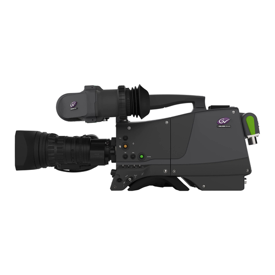
GRASS VALLEY LDX FLEX User Manual
Software upgradable camera platform ldx series
Hide thumbs
1
2
Table Of Contents
3
4
5
6
7
8
9
10
11
12
13
14
15
16
17
18
19
20
21
22
23
24
25
26
27
28
29
30
31
32
33
34
35
36
37
38
39
40
41
42
43
44
45
46
47
48
49
50
51
52
53
54
55
56
57
58
59
60
61
62
63
64
65
66
67
68
69
70
71
72
73
74
75
76
77
78
79
80
81
82
83
84
85
86
87
88
89
90
91
92
93
94
95
96
97
98
99
100
101
102
103
104
105
106
107
108
109
110
111
112
113
114
115
116
117
118
119
120
121
122
123
124
125
126
127
128
page
of
128
Go
/
128
Contents
Table of Contents
Bookmarks
Table of Contents
Declaration of Conformity
Table of Contents
Cautions and Warnings
Important Information
Chapter 1 - Introduction
Welcome
About this Guide
Related Documents
Technology
Xensium-FT Imagers
Superior Digital Processing
Designed for the Operator
Camera Versions
GV-Elicense Program
Key Features
List of Accessories
Chapter 2 - Installation
Mounting a Lens
EC 270 Eyecatcher Viewfinder
Mounting the Viewfinder
Positioning the Viewfinder
Distance Viewing
AJ-MC700 Microphone
LDK 5301/10 Tripod Adapter Plate
Adjusting the Shoulder Pad
Exchanging the Camera Adapter
Preparation
Attaching the Adapter
Detaching the Adapter
LDK 5020/05 Universal Transport Case
Packing for Return
Chapter 3 - Configurations
Transmission Systems
Fiber Configuration
Triax Configuration
Superxpander Configuration
Chapter 4 - Operating Instructions
Using the Camera
Switching on the Power
Controlling the Camera
Location of Controls
Using the OCP 400
Using the Camera Menu
Entering the Camera Menu
Finding Your Way
Leaving the Camera Menu
Making Value Changes
Undoing Changes
User Buttons
Left Side Panel Buttons
Lens Buttons
Handgrip Button
Viewfinder Controls (Eyecatcher Only)
Viewfinder Information
Indicators
On Screen Marker Indicators
Viewfinder LED Indicators (Eyecatcher Only)
Information Screen
Focus Assist
Viewfinder Zoom
Lens Operation
Back Focus Adjustment
Class
Auto Iris
Extended Iris
Precision Focus
Lens Indicators in the Viewfinder
Controls on the Camera Adapter
Overview of Controls
Powering the Camera
Selecting Monitoring Signals
Audio
Intercom
Communication
Call Button
Pickme Button
Private Data
Tracker Tally Signal
Managing Files
Scene Files
Operator Files
Lens Files
Standard Files
Access and Security
User Level
Selecting the User Level
Disable Camera
Access Control
Chapter 5 - Video Setup
Video Settings
Standard Settings
Video Mode
Sensitivity Mode
Color Bar
Gain
Gamma
Gamma Correction
Gamma Curve
Gamma Presets
Contrast
Contrast Adjustment
Black Stretch
Knee
Knee (in Powercurves Mode)
Knee (in Compatibility Mode)
Optical Filters
Exposure
Exposure Time
Lighting Correction
V-Shift (Vertical Acquisition Shift)
Variable Exposure Time
Color
Color Temperature
Color Tint
Color Filter
Selecting Color Temperature
Variable Color Temperature
Auto White Balance
Saturation
Color Protect
Secondary Color Correction
Sharpness
Detail
Texture
Detail Equalizer
Skin Detail
Image Control
Freeze Frame
Reverse Scan
Chapter 6 - Camera Menu Reference
Reference Tables
Operator Toolbox Menu
Production Setup Menu
Creative Control Menu
Configuration Menu
Licenses Menu
Diagnostics Menu
Service Menu
Chapter 7 - Maintenance
Installing Elicenses
About Elicenses
Installation Procedure
Black Calibration
Formatting the SD Card
Chapter 8 - Connectors
Camera Head
Viewfinder Connector
Network Connector
USB Connector
HDMI Connector
Lens Interface Connector
Front MIC Connector
Camera Adapter
Back Panel
Transmission Connector
Audio/Vf Connector
HD-SDI(B)/VF Connector
HD-SDI(A) Connector
Microphone 1 + 2 Connectors
Intercom Headset Connector
Power Output Connector
Script Light Connector
Power Input Connector
Side Panels
Reference Input / Teleprompter Output Connector
Auxiliary Connector
Tracker Connector
Main Video Signals
Chapter 9 - Specifications
Specifications for LDX Series Camera Head
General
Camera
Video Modes
Connectivity
Dimensions
Specifications for LDX 5421 3G Fiber Adapter
Technical
Dimensions
Specifications for LDX 5419 3G Triax Adapter
Technical
Dimensions
Advertisement
Quick Links
Download this manual
User's Guide
3922 496 32101 June 2013 v3.1
Package v10
LDX Series
Software Upgradable Camera Platform
Table of
Contents
Previous
Page
Next
Page
1
2
3
4
5
Advertisement
Table of Contents
Need help?
Do you have a question about the LDX FLEX and is the answer not in the manual?
Ask a question
Questions and answers
Related Manuals for GRASS VALLEY LDX FLEX
Camcorder GRASS VALLEY LDX Worldcam User Manual
Software upgradable camera platform ldx series (128 pages)
Camcorder GRASS VALLEY LDX Premiere User Manual
Software upgradable camera platform ldx series (128 pages)
Camcorder GRASS VALLEY LDX 86WorldCam User Manual
Ldx 86 series (122 pages)
Camcorder GRASS VALLEY LDX 86 HS User Manual
Hispeed/xtremespeed hd camera + xf fiber adapter (128 pages)
Camcorder GRASS VALLEY LDX Worldcam Series User Manual
Software upgradable camera platform ldx series (128 pages)
Camcorder GRASS VALLEY LDX Premiere Series User Manual
Software upgradable camera platform ldx series (128 pages)
Camcorder GRASS VALLEY LDX 96 Series User Manual
High frame rate/hd/3g/4k camera platform (126 pages)
Camcorder GRASS VALLEY LDK Brochure
(12 pages)
Camcorder GRASS VALLEY LDK 3000 User Manual
Hd camera (102 pages)
Camcorder GRASS VALLEY LDK 8000 Elite User Manual
System camera (122 pages)
Camcorder GRASS VALLEY LDK 8300 User Manual
Hdtv high-speed camera system (106 pages)
Camcorder GRASS VALLEY LDK 8300 User Manual
High-speed hd camera (110 pages)
Camcorder GRASS VALLEY LDK 3000+ User Manual
High-definition camera head (108 pages)
Camcorder GRASS VALLEY LDK 5490 User Manual
Digital cinematographic camera (90 pages)
Camcorder GRASS VALLEY LDK 4000 MKII User Manual
Camera system (108 pages)
Camcorder GRASS VALLEY Ignite SDC Series Instruction Manual
Robotic camera (122 pages)
This manual is also suitable for:
Ldx worldcam
Ldx premiere
Ldx elite
Ldx flex series
Ldx worldcam series
Ldx premiere series
...
Show all
Ldx elite series
Table of Contents
Print
Rename the bookmark
Delete bookmark?
Delete from my manuals?
Login
Sign In
OR
Sign in with Facebook
Sign in with Google
Upload manual
Upload from disk
Upload from URL


Need help?
Do you have a question about the LDX FLEX and is the answer not in the manual?
Questions and answers