Table of Contents
Advertisement
Quick Links
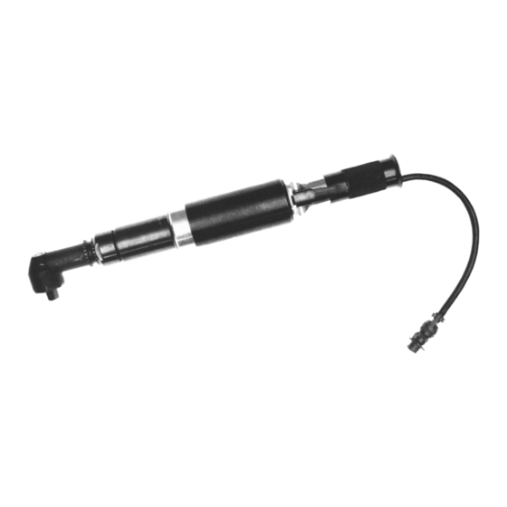
55NJLT & 55NLT Series
Transducerized Nutrunners
Series:
55
Nutrunner:
Clutch Designation:
J
Joint Rate
Stall Type
Handle:
L
Lever
Transducer:
Transducer:
V
Vision (Lights)
VP
Vision (Lights) Positive
Gear Train Designation:
2
4
7
3
6
10
NORTH AMERICA
P.O. Box 1410
Lexington, SC 29071
55
N X L
T
XX
-
XX
Operation & Service Manual
823156
X X
-
X
R Retractable Spindle
Angle Terminations:
M
T
HDB T Hold & Drive
P
V
VHD V Hold & Drive
EUROPE
Postfach 30
D-73461 Westhausen
2/01
Output Drive:
3
3/8"
4
1/2"
S
Built-in Socket
(Specify Size)
T
Threaded Spindle
1
Advertisement
Table of Contents

Related Manuals for Cleco 55NJLT


Summary of Contents for Cleco 55NJLT
- Page 1 Operation & Service Manual 823156 2/01 55NJLT & 55NLT Series Transducerized Nutrunners N X L Series: Output Drive: R Retractable Spindle 3/8" Nutrunner: 1/2" Built-in Socket Clutch Designation: (Specify Size) Joint Rate Threaded Spindle Angle Terminations: Stall Type HDB T Hold & Drive Handle: VHD V Hold &...
-
Page 2: Safety Recommendations
Occupational Noise Exposure, and American National Standards Institute, ANSI S12.6, Hearing Protectors. Cleco nutrunners are designed to operate on 90 psig (6.2 Tool balance arms are available to absorb the torque bar) maximum air pressure. If the tool is properly sized and reaction of the tool while balancing the weight of the tool applied, higher air pressure is unnecessary. - Page 3 Safety Recommendations • Tasks should be performed in such a manner that the Some individuals may be susceptible to disorders of the wrists are maintained in a neutral position, which is not hands and arms when performing tasks consisting of highly flexed, hyperextended, or turned side to side.
- Page 4 threads) the motor housing. Hold the tool in a vertical position OPERATING INSTRUCTIONS with the right angle head up. Unscrew (left hand threads) and remove the head and transducer housing from the motor 55 STALL-TYPE NUTRUNNERS housing. Disconnect the wire connector, No. 202183, at the The 55 stall-type nutrunner is designed to develop maximum transducer and remove the transducer and gear train from the rated torque at 90 psig.
-
Page 5: Safety Check
suitable driver, drive the pinion gear out of the right angle housing. Gear Train - 2, - 3, - 4, - 6, & - 10 Important: Do not bend, strike, push or pull in any way that will .0015" cause strain in the plastic coated area of the transducer. Clearance Remove the gear train from the front of the ring gear. -
Page 6: Transducer Specifications
TRANSDUCER SPECIFICATIONS MAXIMUM TORQUE CAPACITY See full scale values below OUTPUT VOLTAGE (Vo) 2 Millivolts per volt at maximum torque capacity BRIDGE RESISTANCE (Rbr) 700 ohms (nominal) can be used with 350 and 700 ohm strain gage equipment* TRANSDUCER CABLE Cannon No. - Page 7 55 & 75 TRANSDUCER TOOL WIRING DIAGRAM 19 PIN CONNECTOR + EXCITATION WHITE WHITE BLACK - EXCITATION TRANDUCER BLACK GREEN + SIGNAL GREEN CAMBION CONNECTORS - SIGNAL SHIELD SHIELD YELLOW LED SIGNAL WHITE WHITE INDICATOR WHITE COMMON WHITE LIGHTS WHITE WHITE WHITE GREEN LED SIGNAL...
- Page 8 "M" RIGHT ANGLE HEAD 842517 867520 867521 867522 382633 882629 867506 863360 867519 843589 847219 867642 867641 864396 842517 847710 864076 867643 FLUSH SOCKET SPINDLE SIZE SPINDLE CONVERSION PART NO. KIT* PART NO. 10mm 202566 201102 11mm 202725 201214 13mm 202567 201103 869051 202569...
- Page 9 "P" RIGHT ANGLE HEAD 842517 867520 867521 867522 382633 864105 203247 867546 203252 203253 844017 3/8" SQ. DR. 844014 1/2" SQ. DR. 844016 3/8" SQ. DR. 844013 844011 1/2" SQ. DR. 203439 3/8" SQ. DR. 847272 203251 203249 1/2" SQ. DR. 203248 842517 203250...
- Page 10 "T" RIGHT ANGLE HEAD 842517 867520 867521 867522 382633 882661 867507 867546 867511 867548 844014 844011 844013 867997 867510 867512 867547 867509 867787 1/2 - 20 Thd. DRILL SPINDLE PARTS LIST—"T" Right Angle Head * Denotes parts not included in subassemblies listed below. Part No.
- Page 11 "T" HEAD — RETRACTABLE SPINDLE PARTS LIST — RETRACTABLE SPINDLE PART NO. NAME OF PART QTY. 202537 1/2" SQUARE DRIVE EXTENSION SPINDLE (INCLUDES 844011, 844013, 844014, & PIN) 202538 RETRACTABLE SPINDLE 202539 RETAINER CLIP 202540 SPRING 844011 SOCKET RETAINER 844013 SOCKET SPRING RETAINER 844014 SOCKET RETAINER SPRING...
- Page 12 45 & 55 -2, -3, -4, & -6 Gear Trains Part No. Model 867526 RIGHT ANGLE HEAD Part No. Model 867526 844774 867523 844774 TRANSDUCERIZED 867523 Part No. Model 844774 203106 844774 Part No. Model 203107 832125 GEAR TRAINS NONE 202605 203106 204809...
- Page 13 55 TRANSDUCERIZED JOINT RATE DEVICE 201338 JOINT RATE ONLY 842274 203157 STALL ONLY 865779 847807 412055 869568 869564 PARTS LIST — 55 TRANSDUCERIZED JOINT RATE DEVICE PART NO. NAME OF PART QTY. PART NO. NAME OF PART QTY. 201338 Drive Shaft Subassembly 847807 Spring (Joint Rate Device)
-
Page 14: Parts List - Motor
55 TRANSDUCERIZED MOTOR 203099 Stall Tools 863887 203100 Joint Rate Tools 843444 867536 865352 619377 869572 869569 203101 202396 869938 JOINT RATE ONLY PARTS LIST — MOTOR PART NO. NAME OF PART QTY. 202396 Motor Spacer 203099 Rotor-Hex (Stall Tools) 203100 Rotor-Hex (Joint Rate Tools) 203101... - Page 15 55 TRANSDUCERIZED MOTOR HOUSING AND HANDLE Wire Bundle For Tool Without Light Kit Part No. No. of App. Pins Lgth. 202179 26" 202573 11 3/8" 864533 203611 12" 203610 29" Wire Bundle For Tool With Light Kit 202180 202724 Part No. No.
- Page 16 "T" RIGHT ANGLE HOLD & DRIVE HEAD 842517 867520 867521 867522 382633 812667 203390 203393 203387 867546 203391 8675480 867997 847219 203392 STD. 203497 OPT. 867642 867641 203389 STD. 812023 203496 OPT. 512077 203950 842274 869025 203951 869013 203710 1/4" INTERNAL HEX. PART NO.
- Page 17 "V" RIGHT ANGLE HOLD & DRIVE HEAD 204347 847659 204348 867924 204343 867546 204356 869880 864711 864712 864710 867997 204350 204349 204346 622772 204344 842160 617290 204355 204345 PART NO. DESCRIPTION QTY. 204343 ANGLE HEAD 204344 DRIVE SPINDLE 204345 BEARING CAP 204346 HOLD SPINDLE 204347...
- Page 18 55 "V" RIGHT ANGLE HOLD & DRIVE HEAD GEAR TRAINS -2, -3, -4, & -6 GEAR TRAINS Part No. Model 867526 Part No. Model 867526 844774 867523 844774 867523 Part No. Model 844774 203106 844774 Part No. Model 203107 832125 NONE 202605 203106...
- Page 20 670 Industrial Drive Lexington, SC 29072 Phone: (803) 359-1200 Fax: (803) 359-2013...
Need help?
Do you have a question about the 55NJLT and is the answer not in the manual?
Questions and answers