
Related Manuals for Cleco 80PTHD Series


Summary of Contents for Cleco 80PTHD Series
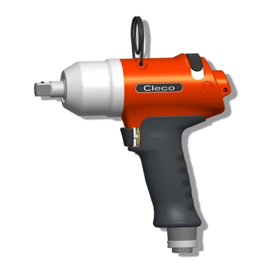
- Page 1 Instruction Manual P1885E/EN 2008-07 80PTHD… Pulse shut-off nutsetter For additional product information visit our website at http://www.apextoolgroup.com...
- Page 2 Identifies an index number, see 8 Spare parts, page 25 In graphics: Identifies movement in a direction. Identifies function and force. In pictured illustrations: Where not necessary, 80PTHD… (air from buttom) is shown. Nomenclature × × Max. capacity Output drive 80 –...
-
Page 3: Table Of Contents
Disassembling the throttle valve ............19 Disassembling the pulse unit .............. 20 Assembling the motor unit ..............20 Assembling the pulse unit..............24 Spare parts Pistol grip 80PTHD…................26 Pistol grip 80PTHDA… ............... 28 Motor unit 935635................30 P1885E/EN 2008-07 P1885E-EN_80PTHD_2008-07IVZ.fm, 27.10.2010... - Page 4 Pulse unit .................... 32 Equipment order list................34 Technical data Dimensions 80PTHD… in mm............35 Dimensions 80PTHDA… in mm ............36 Performance Data................36 Service Disposal P1885E/EN 2008-07 P1885E-EN_80PTHD_2008-07IVZ.fm, 27.10.2010...
-
Page 5: Safety
Safety Safety Warnings and notes Warning notes are identified by a signal word and a pictogram: • The signal word describes the severity and the probability of the impending danger. • The pictogram describes the type of danger. WARNING! Indicates a potentially hazardous situation which, if not avoided, could result in death or serious injury. -
Page 6: Basic Requirements For Safe Working Practices
Safety Basic requirements for safe working practices You should read all instructions. Failure to observe the instructions listed below can result in serious injuries. CAUTION! Before initial operation, check that the suspension bail is properly fastened to the bal- ➔ ancer. -
Page 7: Personal Protective Equipment
Sound level in the area of the user > 80 dB(A), danger of hearing damage • Wear hearing protection. Designated use The 80PTHD… is designed exclusively for fastening and releasing threaded fasteners. • Do not use it as a hammer. •... -
Page 8: Product Description
Items supplied Product description Operation and functional elements 80PTHDA… Alternative Position 80PTHDA… Pos. Designation Reverse switch Torque adjustment, siehe 4.5.1 Setting the torque, page 10 Speed adjustment, siehe 4.5.2 Changing the speed, page 11 Air inlet Connection for Pneumatic Torque Verifier TVP100, signal connection kit, order no. -
Page 9: Before Initial Operation
Before initial operation Before initial operation Ambient conditions Ambient temperature 41 °F (5 °C) to a maximum of +104 °F (+40 °C) Permissible relative humidity 25 to 90 %, non-condensing Air supply Parameter Data Air hose Inner diameter 1/2" (ø 12,5 mm), maximum length 16.4 ft (5 m) Working pressure range 58 to 101.5 psi (400 to 700 kPa) -
Page 10: Setting Up The Tool
Before initial operation Activate the compressed air. ➔ 4.4.1 Testing Carry out a test in clockwise and coun- ➔ terclockwise rotation at maximum speed, see 4.5.2 Changing the speed, page 11. Check the speed at the output drive. ➔ Target: n > 6000 rpm. Setting up the tool The tool must be configured for the desired rundown. - Page 11 Before initial operation 1. Hold the output drive firmly. 2. Carefully push the size 2 hex wrench through the hole of the pistol grip housing until it reaches the torque adjustment screw 3. Turn the torque adjustment screw and roughly set the required torque, Torque see Abb.
-
Page 12: Troubleshooting
Troubleshooting 4.5.3 Measuring the torque We recommend carrying out a static torque measurement by retightening the rundown. When carrying out a dynamic measurement using a transducer adapter, also carry out a static test, for example using a torque wrench (electronic). Troubleshooting Error Possible causes... -
Page 13: Maintenance
Maintenance Maintenance CAUTION! Danger of injury due to unintentional activation – before service, disconnect the tool from the compressed air supply. Service schedule Regular maintenance reduces operating faults, repair costs and downtime. Mainte- Rundowns Measures nance interval 100,000 Check the suspension bail for functional safety. ➔... - Page 14 Maintenance 6.1.1 Calculating a customer-specific maintenance plan A service interval W(1,2,3) depends on the following factors: Factor Value assumed in Description 6.1, "Maintenance plan" V1 = 100,000 Number of rundowns after a maintenance measure is pre- V2 = 500,000 scribed by Cooper Power Tools GmbH & Co. OHG. V3 = 1,000,000 1.8 seconds Specific rundown time, measured in life and endurance tests.
-
Page 15: Activating The Reserve Oil
Maintenance Activating the reserve oil If pulse build-up stops, some of the oil in the pulse unit has been used up. The reserve oil must be activated. If the equalizing piston reaches the limit stop, oil must be refilled the next time (see 6.3 Refilling oil, page 16). -
Page 16: Refilling Oil
Maintenance Refilling oil Approx. 7 oz. Approx. 0.35 oz (10 ml) – Item Designation Oil filling device asm. Oil filling device without filling piece Filling piece asm. Oil order no. 925715, ESSO-UNIVIS HVI26, approx. 2.1 qt (2 liters), temperature 68 ±9 °F (20 ±5 °C) Quick disconnect coupling Working pressure 65 –... - Page 17 Maintenance Remove the threaded pin 15 and ball 14. Remove the O-ring 12 and sleeve 13. Align the output drive and claw as shown in the illustration, see 6.2 Activating the reserve oil, page 15. Rotate the equalizing piston 11 clockwise as far as it will go until X = 0 (starting point). Unscrew the equalizing piston 11 counterclockwise by 1,0 turns (reserve oil volume).
- Page 18 Maintenance P1885E/EN 2008-07 86c_Wartung en bedingt.fm, 27.10.2010...
-
Page 19: Repair Instructions
Repair instructions Repair instructions Refer also to 8 Spare parts, page 25 and 8.5 Equipment order list, page 34 Disassembling the motor unit <C3> <C3> <61> <C2> <54> <C1> <59> <C1> <59> Changing blades Changing bearing / rotor Disassembling the throttle valve Size 3/8"... -
Page 20: Disassembling The Pulse Unit
Repair instructions Disassembling the pulse unit Size 1/2" CAUTION! Skin irritation in case of direct contact with oil. Wear protective gloves. <D> CAUTION! Hydraulic blade is under spring pressure! <65> Wear protective goggles. NOTE Permitted only if filling is guaranteed with oil filling device, see 6.3 Refilling oil, page 16. - Page 21 Repair instructions 7.4.1 Assembling the end plate <59> <C8> <54> <59> <54> <55> <C4> <C5> <C6> <C7> Dimension X = 0.00" to 0.00236" (0.00 to 0.06 mm) 1. Press in <59>, see dimension X. Test force 1.12 – 3.37 lbf (5 – 15 N) Dimension Y = 0.0002"...
- Page 22 Repair instructions 7.4.2 Assembling the shut-off piston Size 4 <44> Do not use grease – <45> to hold the balls in place! <47> <48> <49> (3×) <59> <44> <47> <50> P1885E/EN 2008-07 86d_Reparatur en bedingt.fm, 27.10.2010...
- Page 23 Repair instructions 7.4.3 Assembling the actuating ring <E> <E> <32> <32> click! <34> <44> <40> 33 (3 ) <47> <55> <56> <60> Dimension X <34> < 0.053" (1,35 mm) 935465 0.059±0.0059" (1,5±0.15 mm) 935464 > 0.065" (1,65 mm) 935463 <34> <44>...
-
Page 24: Assembling The Pulse Unit
Repair instructions Assembling the pulse unit NOTE To prevent damage, lubricate the gaskets and o-rings using grease (order no. 914392) before assembly. 7.5.1 Assembling the hydraulic blades <73> <78> <77> <73> <F1> <F1> <77> <75> <76> <74> Size 1/2" <73> <F2>... -
Page 25: Spare Parts
Spare parts Spare parts Note Always use only original CLECO replacement parts. Failure to comply with this instruction can result in decreased performance and an increased need for maintenance. Installing replacement parts from other manufacturers will void all manufacturer's warranties. -
Page 26: Pistol Grip 80Pthd
Spare parts Pistol grip 80PTHD… 0,7±0,1 Nm 0.5±0.1 lbf.ft 1 / ISO 4757 click (22) (24) 0,7 ±0,1 Nm 0.5 ±0.1 lbf.ft 935490 SW2 1,5+0,2 Nm 1.1+0.15 lbf.ft 3+1 Nm 931030 SW2,5 2.2+1 lbf.ft <G>: 933375 20+2 Nm 14.8+1.5 lbf.ft... - Page 27 Spare parts 1)Order no. 2)Quantity 3)Part of motor service kit K1, order no. 935655 4)Dimesions P1885E/EN 2008-07 85e_Ersatzteile en.fm, 27.10.2010...
-
Page 28: Pistol Grip 80Pthda
Spare parts Pistol grip 80PTHDA… 0,7±0,1 Nm 8 +1 Nm 0.5±0.1 lbf.ft 6 +1 lbf.ft 1 / ISO 4757 SW17” 1,5+0,2 Nm 1.1+0.15 lbf.ft 931030 SW2,5 click (22) (24) 0,7 ±0,1 Nm 0.5 ±0.1 lbf.ft 935490 SW2 3+1 Nm 2.2+1 lbf.ft <G>: 933375 20+2 Nm 14.8+1.5 lbf.ft... - Page 29 Spare parts 1)Order no. 2)Quantity 3)Part of motor service kit K1, order no. 935655 4)Dimesions Connection for evaluation electronics TVP100 Adhesive, order no. 914860 Grease, order no.-Nr. 914392 P1885E/EN 2008-07 85e_Ersatzteile en.fm, 27.10.2010...
-
Page 30: Motor Unit 935635
Spare parts Motor unit 935635 Axial clearance, see 7.4.1 Assembling the end plate, page 21 Reference dimension X, see 7.4.3 Assembling the actuating ring, page 23 P1885E/EN 2008-07 85e_Ersatzteile en.fm, 27.10.2010... - Page 31 Spare parts 1)Order no. 2)Quantity 3)Part of motor service kit K1, order no. 935655 4)Dimesions P1885E/EN 2008-07 85e_Ersatzteile en.fm, 27.10.2010...
-
Page 32: Pulse Unit
Spare parts Pulse unit Tightening torque, see 7.5 Assembling the pulse unit, page 24 For disassembly, note the position of the balls in the control disc. Reassmble the balls in the same position. (70) fest 1+0,3 Nm tight 0.75+0.25 lbf.ft 902904 ø53 935490 SW2 P1885E/EN 2008-07... - Page 33 Spare parts 1)Order no. 2)Quantity 3)Part of hydraulic service kit K2, order no. 935656 4)Dimesions Order no. <65> <73> <96> <97> <98> <99> <100> 80PTHD604 935641 935600 – – – – – 80PTHDA604 80PTHD60Q 935640 935961 903231 935634 935648 935649 935651 80PTHDA60Q P1885E/EN 2008-07...
-
Page 34: Equipment Order List
Spare parts Equipment order list 1)Order no. P1885E/EN 2008-07 85e_Ersatzteile en.fm, 27.10.2010... -
Page 35: Technical Data
Technical data Technical data Dimensions 80PTHD… in mm Abb. 9-1 P1885E/EN 2008-07 85f_TechnDaten en.fm, 27.10.2010... -
Page 36: Dimensions 80Pthda
Technical data Dimensions 80PTHDA… in mm Abb. 9-2 Performance Data Order no. Recommended Free Air consumption torque range speed ft.lbf (Nm) 10.9 /min (m /min) min. max. lb (kg) Free speed Pulses 80PTHD604 3.1 (1,40) 1/2" 80PTHDA604 3.2 (1,45) 37 (50) 59 (80) 6000 26.5 (0,75) -
Page 37: Service
Service Service NOTE If repair is required send the complete 80PTHD… to Cooper Power Tools GmbH & Co. OHG. It may be repaired only by authorized technicians. If the tool is opened, the warranty is voided. Disposal CAUTION! Injuries and environmental damage from improper disposal. - Page 38 Sales & Service Centers Note: All locations may not service all products. Please contact the nearest Sales & Service Center for the appropriate facility to handle your service requirements. Dallas, TX Detroit, MI Houston, TX Lexington, SC Apex Tool Group Apex Tool Group Apex Tool Group Apex Tool Group...
Need help?
Do you have a question about the 80PTHD Series and is the answer not in the manual?
Questions and answers