Table of Contents
Advertisement
Quick Links
Download this manual
See also:
Instruction Manual
17BP
Cordless EC tool
Series
17
Type
B - Battery
Tool model
P - Pistol
N O R T H A M E R I C A
P.O. Box 1410
Lexington, SC 29071-1410
17 B P XX Q S
Retain for future reference!
Instruction Manual
P1846E/EN
S - Depth sensor
Attachment
Q - Quick change chuck 1/4"
Max. torque
E U R O P E
Postfach 30
D-73461 Westhausen, Germany
02/06
Optional
13 - 13 Nm
09 - 9 Nm
07 - 7 Nm
05 - 5 Nm
Advertisement
Table of Contents

Related Manuals for Cleco 17BP


Summary of Contents for Cleco 17BP
-
Page 1: Instruction Manual
Instruction Manual P1846E/EN 02/06 17BP Cordless EC tool 17 B P XX Q S Optional Series S - Depth sensor Attachment Type Q - Quick change chuck 1/4" B - Battery Max. torque Tool model 13 - 13 Nm P - Pistol... - Page 2 - be transferred into another natural or machine-readable language in any form without the express authorization of Apex Tool Group. In the text: 17BP represents all models of the cordless EC tools as described here. refers to required actions. •...
-
Page 3: Table Of Contents
General description................9 Operation and functional elements ............. 10 3.2.1 LED lighting ..................11 3.2.2 IrDA interface port................11 3.2.3 Depth sensor (only with 17BP…S) ............. 11 3.2.4 LED display..................12 3.2.5 Rechargeable Battery ................. 12 3.2.6 Start button ..................12 3.2.7... - Page 4 10.1.1 Dimensions tool holder (Optional) ............43 10.2 Performance Data................43 10.3 Electrical data ..................44 10.3.1 Battery power supply ................44 10.3.2 Output stage servo electronic ............. 44 10.3.3 IrDA interface port................45 10.3.4 Torque transducer................45 Disposal Glossary P1846E/EN 02/06 P1846E_EN 17BP 0206IVZ.fm, 12.04.2006...
-
Page 5: Safety
Safety Safety Presentation of notes Warning notes are identified by a signal word and a pictogram: • The signal word describes the severity and the probability of the impending danger. • The pictogram describes the type of danger. Warning! Possible hazardous situation for the health of persons. If this warning is not observed, very serious injury may result. -
Page 6: Basic Requirements For Safe Working Practices
Hold the 17BP tightly in the hand – be prepared for high short-term reaction torques. Do not carry the 17BP with the finger on the start button – prevent accidental operation. Do not open the battery. Contact with acid will cause injury. -
Page 7: Proper Use
The 17BP is intended to screw in and loosen threaded joints. The model with depth sensor (17BP…S) also allows you to screw in tapping screws. The 17BP should only communicate via the IrDA interface port of the tool holder (Order no. 935144) with the control unit TMEB-100 or a PC. -
Page 8: Scope Of Supply, Transport And Storage
Protect the 17BP and battery from moisture. Do not bring any electrically conducting objects such as paper clips, coins, keys, nails or screws in contact with the battery contacts. When storing the battery outside of the 17BP or battery charger, cover the battery contacts. Object... -
Page 9: Product Description
RS232. • Rundown data is sent to the TMEB-100 controller or a PC by placing the 17BP into the tool holder. Data is transmitted from the tool holder to the 17BP via the IrDA interface port (infrared). -
Page 10: Operation And Functional Elements
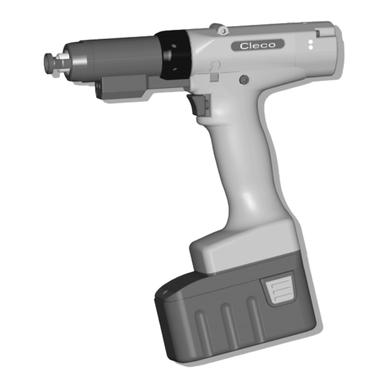
Operation and functional elements This chapter describes the operating and functional elements and their functions: Fig. 3-1: LED lighting IrDA (infrared interface port) Depth sensor (only with 17BP…S) LED display Rechargeable battery Start button Reverse switch LCD display with information on torque, angle and status Function keys Set torque –... -
Page 11: Led Lighting
TMEB-100 or a PC. For data transmission and programming of the 17BP, place the 17BP in the tool holder. A data transmission is possible in the operating modes Active, Energy saving mode and Stand-by, but not possible in Sleep (see 5.2 Operating modes , page 17). -
Page 12: Led Display
Product description 3.2.4 LED display The LED display shows each operating mode and the result of the last screwing cycle (see 5.2 Operating modes , page 17): LEDs Operating status Result after screwing cycle Steady light Green Active Steady light Red Active Flashing light Green –... -
Page 13: Reverse Switch
Product description 3.2.7 Reverse switch The reverse switch changes the rotation direction of the 17BP: Clockwise rotation – for screwing in screws Press reverse switch to detent. When the start button is pressed Active appears on the LCD display. Counterclockwise rotation – for loosening or screwing out screws Press reverse switch to detent. -
Page 14: System Overview - Optional Accessories
10 m Part no.935157 Screw inserts (Recommendation GETA / APEX): Pulling connection according to DIN 3126 shape E 6.3 (hexagon insert bit ¼“) Prescribed length 49 mm at 17BP…S (with depth sensor) Fig. 3-3: System overview – optional accessories P1846E/EN 02/06... -
Page 15: Before Initial Operation
Before initial operation Before initial operation The 17BP has been configured by Apex Tool Group. A setting for your specific screw joint needs must only be made with the controller TMEB-100 or a PC by a qualified person. See the following: •... -
Page 16: Replacing The Battery
Check the screw inserts for visible damage and breaks. Replace damaged screw inserts immediately. Before replacing the screw inserts, disconnect the 17BP from the battery . Only use screw inserts for machine-controlled fastening tools. Ensure that the tool inserts lock in securely. -
Page 17: First Operation
First Operation Perform the screw operation Before first operation of the 17BP, ensure that the battery is firmly in place. The 17BP is now ready for use. After you press and release the start button, the LCD display shows the message Ready. - Page 18 First Operation P1846E/EN 02/06 46b_1_5 en.fm, 12.04.2006...
-
Page 19: Lcd Display
Requested motor output is too high TMAX Maximum fastening time exceeded Rundown terminated by disabled start signal Depth sensor signal was active at Start or deactivated during the fastening process (Series 17BP only) Tq< Torque too low Tq> Torque too high A<<... -
Page 20: Status
LCD display Status RUN Screen Ready Ready is displayed when no other status message takes precedence and the tool is ready for operation. Standard operating mode Remain Standard mode is selected when Linking is not activated. The application is selected at the Run Screen or via the App. -
Page 21: Set Position (Only Allowed With Linking)
LCD display Set position (only allowed with Linking) Activate Set position Hold 3 sec. To activate the Set position menu, you must hold down the right-hand button for three seconds. NOTE Set position can only be enabled if TMEB-100 is activated in the Advanced application builder\System settings\Set tool enable position menu. -
Page 22: Communications
LCD display Deactivate Set position Hold 3 sec. To deactivate the Set position menu, you must hold down the right-hand button for three sec- onds. Leave menu After three seconds, the message Leave Menu is displayed and you can release the right-hand button. - Page 23 LCD display Linkin Result No Linking result; Linking was terminated without an overall result. Not all of the positions in the tightening group have been programmed. Check the selected appli- cation or tightening group at the TMEB-100 to see if tool settings and process programming have been performed.
-
Page 24: Diagnostics
LCD display Sync Error Error during last synchronization of data with the TMEB-100; the tool must be synchronized with the TMEB-100 again. Tool Init Tool has not yet been synchronized with a TMEB-100; the tool must be synchronized with the TMEB-100 for the first time. Input Enable Missin... - Page 25 LCD display Diag locked If diagnosis is not enabled, the message Diagnosis Disabled is displayed. Test menu After three seconds, the message Test Menu is displayed and you can release the left-hand but- ton. The first Test Function (display tool system time) is then shown. NOTE While test functions are active, fastening cannot take place, or only the test function parameters can be used.
- Page 26 LCD display Display Counter Display Counte 999999 The tool counter display is incremented after each rundown throughout the service life of the tool. You can also view the counter display on the TMEB-100 under Diagnosis\Tool\Tool Memory. Display calibration test Cal OK K 1.11 O 0.00 This test function cyclically recalibrates the system with the values used immediately before the...
- Page 27 LCD display Monitoring criteria are the torque and a monitoring time. If the torque exceeds 15 % of its calibration value (even during the dwell time), or if the monitor- ing time of 4 seconds expires, the test run is terminated with a TQ> or TMAX result. The user must check, if the output shaft has actually turned by the value indicated (e.
- Page 28 LCD display Activate Emergency NOTE The emergency function can only be activated if it is activated in the TMEB-100 in the Advanced application builder\System settings\Enable emergency function menu. Emerge Strate locked Emergency function is disabled. Emerge Strate If activated in the TMEB-100 in the Advanced application builder\System settings\Enable emer- gency function menu, the emergency function can be enabled and disabled in the Diagno- sis\Emergency function menu with the tool start button.
-
Page 29: System Fault Messages
LCD display System fault messages NOTE If a fault is displayed, fastening is disabled until the fault is acknowledged with the left-hand but- ton on the tool. In the event of serious hardware faults, the tool is not enabled again even after the fault is acknowledged, and must be returned to the manufacturer for repair. - Page 30 LCD display Servo Error The current setpoint has been exceeded. Remedy: there may be a short-circuit. Return tool to manufacturer for repair. Servo Error Temp > The Servo has overheated. Remedy: Switch the tool off for a time so that it can cool down. Increase the cycle time, reduce the fastening time or the torque.
- Page 31 LCD display Servo Error Angle Tool angle encoder is sending incorrect signals to the Servo amplifier. Remedy: Return tool to manufacturer for repair. voltag warnin Warns that battery is running low. Remedy: Recharge battery or replace it with one that is already charged. Tool Error Counte...
- Page 32 LCD display Transd Error Transducer calibration voltage fault. Remedy: Tool was not relaxed at time of calibration. Allow tool to relax and try again. If this does not help, return to tool to the manufacturer for repair. Transd Error Transducer offset voltage fault. Remedy: Tool was not relaxed at time of calibration.
-
Page 33: Maintenance
Service schedule Regular service is required to prevent operational failures, repair costs and idle times. Caution! Danger of injury due to unintentional activation – before service – disconnect the 17BP from the battery. After... fastening cycles Actions 100,000 Check housing components for damage... -
Page 34: Disassembling The Gear Box
Maintenance Disassembling the gear box Notes If the 17BP is opened, the warranty is voided. The gearbox should only be opened by qualified specialised personnel. Carefully clamp the 17BP on the pistol Part no. grip into a vice with plastic jaws. - Page 35 Spare parts Note Use only original CLECO spare parts. Failure to comply can result in reduced performance and increased service requirements. If spare parts not manufactured by us are installed, the tool manufacturer is entitled to deny any warranty claims.
-
Page 36: Spare Parts Gear
Spare parts Gear 56 (3×) 60 (3×) 17BP05Q(S) 935101 542230 541894 935093 541894 541899 17BP07Q(S) 935102 542233 541897 934878 17BP09Q(S) 935103 542231 541894 935093 541893 – 17BP13Q(S) 935104 542232 541897 934878 7.2 Lubrication Products , page 33 P1846E/EN 02/06 46e_Ersatzteile en.fm, 12.04.2006... - Page 37 Spare parts Index Benennung Description 800116 Sicherungsring circlip 25,98X0,94 IR 541887 Scheibe washer 542724 O-Ring o-ring 28,24X 0,78 542722 Zahnkranz toothed ring Planetenrad idler gear 923095 Nadelkranz needle rim 3,X5,X 7, Planetenradträger gear gage 541888 Zylinderstift cylinder pin Planetenrad idler gear 923095 Nadelkranz needle rim...
-
Page 38: Tool Holder With Irda Interface
Spare parts Tool holder with IrDA interface P1846E/EN 02/06 46e_Ersatzteile en.fm, 12.04.2006... - Page 39 Spare parts Index Benennung Description Köcher kpl. mit IrDA- tool holder with IrDA 935144 Schnittstelle interface 935172 Köcher, Gummi holster rubber 935174 Buchse plug 935170 IrDA-Serial Adapter IrDA-Serial Adapter 57,6KBIT/S 935175 Halterplatte mounting plate 935173 Schrauberauflage screwdriver support 918688 Senkschraube countersunk screw M 6X 12 935171...
- Page 40 Spare parts P1846E/EN 02/06 46e_Ersatzteile en.fm, 12.04.2006...
-
Page 41: Service
The type-specific calibration data is saved on the integrated screw electronic system in the delivery state of the CLECO tool. If service is requires to change the torque transducer, the screw electronic system or if a recalibration is required, please send the CLECO tool to Apex Tool Group. -
Page 42: Technical Data
Technical Data Technical Data 10.1 Dimensions cordless EC tool 17BP05Q 17BP05QS 17BP07Q 17BP07QS 17BP09Q 17BP09QS 17BP13Q 17BP13QS Fig. 10-1: Dimensions cordless EC tool (mm) P1846E/EN 02/06 46f_Service en.fm, 12.04.2006... -
Page 43: Dimensions Tool Holder (Optional)
Technical Data 10.1.1 Dimensions tool holder (Optional) Fig. 10-2: Dimensions tool holder (mm) 10.2 Performance Data Type Depth Recommended torque Idling Screw Weight Calibration data sensor range speed size without with Torque Angle pulses Rechargeable Rechargeable (nominal) (Resolver) Battery Battery max. -
Page 44: Electrical Data
Technical Data 10.3 Electrical data Tool Protection class III as per DIN EN 61140 (VDE 0140-1) Protection category IP40 as per DIN EN 60529 (IEC 60529 Tool holder Protection class III as per DIN EN 61140 (VDE 0140-1) Protection category IP40 as per DIN EN 60529 (IEC 60529 10.3.1 Battery power supply Battery type... -
Page 45: Irda Interface Port
Disposal 10.3.3 IrDA interface port Supply voltage 5.0 V (4.8 to 5.5 V) Type Power consumption 0.30 VA Maximum current 11 mA Transmission speed: 57.6 kbit/s Parity Bit none Data Bit 8 bit Stop Bit 1 bit Error check Working temperature 0 °C to +40 °C 10.3.4 Torque transducer... -
Page 46: Glossary
Glossary Glossary Angle Angle that is to be reached at the end of the fastening sequence (also final angle, rated angle, or nominal angle). Angle High Limit [AHL] Maximum admissible angle of rotation for a fastening stage. Application Programmed setting of the tool for a specific fastening sequence of up to 6 stages.
Need help?
Do you have a question about the 17BP and is the answer not in the manual?
Questions and answers