Table of Contents
Advertisement
Quick Links
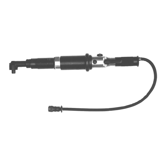
55NLTVC Series Solenoid
Controlled Nutrunners
Series:
55
Nutrunner:
Handle:
L
Lever
Transducer:
Options:
V
Vision (Lights)
VP
Vision (Lights) Positive
Solenoid Controlled:
NORTH AMERICA
P.O. Box 1410
Lexington, SC 29071
55
N
L
T XX C
-
Operation & Service Manual
823013
X
X X
-
X
R Retractable Spindle
Angle Terminations:
M
T
HDB T Hold & Drive
P
V
VHD V Hold & Drive
Gear Train Designation:
2
4
7
3
6
10
EUROPE
Postfach 30
D-73461 Westhausen
2/01
Output Drive:
3
3/8"
4
1/2"
S
Built-in Socket
(Specify Size)
T
Threaded Spindle
1
Advertisement
Table of Contents

Related Manuals for Cleco 55NLTVC Series


Summary of Contents for Cleco 55NLTVC Series
- Page 1 Operation & Service Manual 823013 2/01 55NLTVC Series Solenoid Controlled Nutrunners T XX C Series: Output Drive: R Retractable Spindle 3/8" 1/2" Nutrunner: Built-in Socket Handle: (Specify Size) Lever Threaded Spindle Angle Terminations: Transducer: HDB T Hold & Drive VHD V Hold & Drive...
-
Page 2: Safety Recommendations
Standards Institute, ANSI S12.6, Hearing Protectors. Avoid anything that inhibits blood circulation. Avoid continuous vibration exposure. Cleco nutrunners are designed to operate on 90 psig (6.2 Keep wrists straight. Avoid repeated bending of wrists and hands. bar) maximum air pressure. If the tool is properly sized and applied, higher air pressure is unnecessary. - Page 3 Safety Recommendations cold and dampness, diet, smoking and work practices are Work gloves with vibration reducing liners and wrist sup- thought to contribute to the conditions. ports are available from some manufacturers of industrial work gloves. Tool wraps and grips are also available from Any tool operator should be aware of the following warning a number of different manufacturers.
- Page 4 OPERATING INSTRUCTIONS FOR YOUR SAFETY AND THE SAFETY OF OTHERS, READ AND UNDERSTAND THE SAFETY RECOMMENDATIONS ON PAGES 2 & 3 BEFORE OPERATING A NUTRUNNER. LUBRICATION TORQUE ADJUSTMENT An automatic in-line filter-lubricator-regulator is recom- The 55NLTVC nutrunner is designed to develop maximum mended as it increases tool life and keeps the tool in rated torque at 90 psig.
-
Page 5: Disassembly - General
SERVICE INSTRUCTIONS DISASSEMBLY — GENERAL of the spindle through the bearing I.D. to remove the ball bearing. The driven gear may be removed by pressing the Disconnect tool from air supply. Clamp the right angle head smaller end of the spindle through the gear. Remove the in a vise and loosen (left hand threads) the motor housing. -
Page 6: Safety Check
SERVICE INSTRUCTIONS REASSEMBLY — GENERAL bearing race should be firmly seated and the rotor held forward when checking this clearance. The tool is reassembled in the reverse order of disassem- bly. Clean all parts thoroughly in kerosene and inspect for Pack both rotor bearings with a good grade of No. -
Page 7: Transducer Specifications
TRANSDUCER SPECIFICATIONS MAXIMUM TORQUE CAPACITY See full scale values below OUTPUT VOLTAGE (Vo) 2 Millivolts per volt at maximum torque capacity BRIDGE RESISTANCE (Rbr) 700 ohm (nominal) can be used with 350 and 700 ohm strain gage equipment* TRANSDUCER CABLE Cannon No. - Page 8 SOLENOID SPECIFICATIONS (+) SOLENOID 6V DC-8V DC CONTINUOUS VOLTAGE 24V DC-36V DC FOR 15 msec MAX. 14.95ohm RESISTANCE BLACK (-) SOLENOID TOOL RECEPTACLE CABLE CONNECTORS ADJUSTMENT SCREW SOLENOID RETAINER PLUNGER PIN .015/.020 1. Solenoid plunger pin to hat dimension should be .015/.020 as shown. A new plunger pin should be spaced as shown;...
- Page 9 5/64 HEX WRENCH ADJUSTMENT SCREW SOLENOID RETAINER PLUNGER PIN SOLENOID SEAT VALVE PLUNGER 4. Using a 5/64" hex wrench, turn adjustment screw clockwise until plunger pin is pressed through hat and valve plunger is fully seated in solenoid seat. 5. Depress throttle and check tool for rated speed at 90PSI. If tool does not perform according to specifications, valve plunger may not be fully depressed.
- Page 10 55 & 75 SOLENOID CONTROL TOOL WIRING DIAGRAM 19 PIN CONNECTOR + EXCITATION WHITE WHITE BLACK - EXCITATION TRANDUCER BLACK GREEN + SIGNAL GREEN CAMBION CONNECTORS - SIGNAL SHIELD SHIELD + SOLENOID SOLENOID BLACK BLACK - SOLENOID CAMBION CONNECTORS YELLOW LED SIGNAL WHITE WHITE INDICATOR...
-
Page 11: Name Of Part
"M" RIGHT ANGLE HEAD 842517 867520 867521 867522 382633 882629 867506 863360 867519 843589 847219 867642 867641 864396 842517 847710 864076 867643 FLUSH SOCKET SPINDLE SIZE SPINDLE CONVERSION PART NO. KIT* PART NO. 10mm 202566 201102 11mm 202725 201214 13mm 202567 201103 869051 202569... - Page 12 "P" RIGHT ANGLE HEAD 842517 867520 867521 867522 382633 864105 203247 867546 203252 203253 844017 3/8" SQ. DR. 844014 1/2" SQ. DR. 844016 3/8" SQ. DR. 844013 844011 1/2" SQ. DR. 203439 3/8" SQ. DR. 847272 203251 203249 1/2" SQ. DR. 203248 842517 203250...
- Page 13 "T" RIGHT ANGLE HEAD 842517 867520 867521 867522 382633 882661 867507 867546 867511 867548 844014 844011 844013 867997 867510 867512 867547 867509 867787 1/2 - 20 Thd. DRILL SPINDLE PARTS LIST—"T" Right Angle Head * Denotes parts not included in subassemblies listed below. Part No.
- Page 14 REACTION BAR BRACKET ASSEMBLY 1-5/16" PARTS LIST 3/4" NPT REACTION BAR BRACKET ASSEMBLY PART NO. NAME OF PART QTY. 202319 202319 Reaction Bracket 202320 Reaction Bar Clamp 842554 5/168 x 1/4" Bracket Bolt The complete reaction bar bracket can be purchased as Subassembly using Part No.
- Page 15 45 & 55 -2, -3, -4, & -6 Gear Trains Part No. Model 867526 RIGHT ANGLE HEAD Part No. Model 867526 844774 867523 844774 TRANSDUCERIZED 867523 Part No. Model 844774 203106 844774 Part No. Model 203107 832125 GEAR TRAINS NONE 202605 203106 204809...
- Page 16 55NLTVC MOTOR 869569 863887 843444 202396 203099 867536 203374 865352 619377 203101 869572 PARTS LIST—MOTOR ASSEMBLY PART NO. NAME OF PART QTY. 202396 MOTOR SPACER 203099 ROTOR (NLT) 203101 CYLINDER (INCL. 863887) 619377 FRONT ROTOR BEARING 843444 REAR ROTOR BEARING 863887 CYLINDER PIN 865352...
- Page 17 PARTS LIST 55NLTVC MOTOR HOUSING AND HANDLE PART NO. NAME OF PART QUANITY 2O2012 Muffler 202171 Shut-off Valve Seat 202174 Throttle Valve* 202182 Handle 202183 Cable Connector 202401 Motor Housing 202724 Pipe Cable Protector 203053 Retaining Ring 203259 PC Board (Negative Common)** 203261 Exhaust Deflector** 203262...
- Page 18 "T" RIGHT ANGLE HOLD & DRIVE HEAD 842517 867520 867521 867522 382633 812667 203390 203393 203387 867546 203391 8675480 867997 847219 203392 STD. 203497 OPT. 867642 867641 203389 STD. 812023 203496 OPT. 512077 203950 842274 869025 203951 869013 203710 1/4" INTERNAL HEX. PART NO.
- Page 19 "V" RIGHT ANGLE HOLD & DRIVE HEAD 204347 847659 204348 867924 204343 867546 204356 869880 864711 864712 864710 867997 204350 204349 204346 622772 204344 842160 617290 204355 204345 PART NO. DESCRIPTION QTY. 204343 ANGLE HEAD 204344 DRIVE SPINDLE 204345 BEARING CAP 204346 HOLD SPINDLE 204347...
- Page 20 55 "V" RIGHT ANGLE HOLD & DRIVE HEAD GEAR TRAINS -2, -3, -4, & -6 GEAR TRAINS Part No. Model 867526 Part No. Model 867526 844774 867523 844774 867523 Part No. Model 844774 203106 844774 Part No. Model 203107 832125 NONE 202605 203106...
- Page 22 NOTES...
- Page 23 NOTES...
- Page 24 670 Industrial Drive Lexington, SC 29072 Phone: (803) 359-1200 Fax: (803) 359-2013...
Need help?
Do you have a question about the 55NLTVC Series and is the answer not in the manual?
Questions and answers