
Related Manuals for Omron Sysmac F430-F Series


Summary of Contents for Omron Sysmac F430-F Series
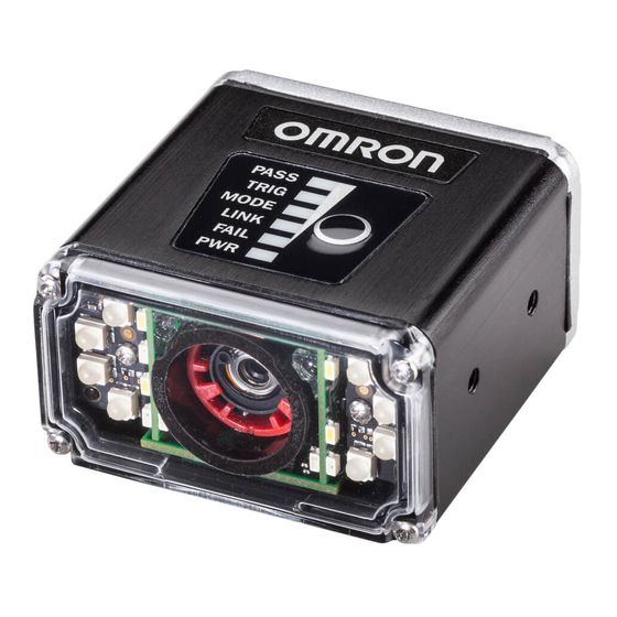
- Page 1 Machine Automation Controller NJ Series Serial (RS-232C) Communications Connection Guide Smart Camera F430-F Series Z442-E-01...
- Page 2 Corporation. Windows is a registered trademark of Microsoft Corporation in the USA and other countries. Sysmac and SYSMAC are trademarks or registered trademarks of OMRON Corporation in Japan and other countries for OMRON factory automation products. Company names and product names in this document are the trademarks or registered...
-
Page 3: Table Of Contents
Contents Related Manuals ..................1 Terms and Definitions ................2 Restrictions and Precautions ..............3 Overview ....................4 Applicable Devices and Device Configuration ........5 5.1. Applicable Devices ................5 5.2. Device Configuration ................6 Serial Communication Settings ............... 8 6.1. -
Page 4: Related Manuals
To ensure system safety, make sure to always read and follow the information provided in all Safety Precautions and Precautions for Safe Use in the manuals for each device which is used in the system. The following Omron Corporation (hereinafter referred to as "Omron") manuals are related to this document: Manual No. -
Page 5: Terms And Definitions
2. Terms and Definitions Term Description / Definition Protocol Macro This function enables data Send / Receive with general-purpose external devices by storing the data Send / Receive procedure (Protocol) used with the general-purpose external devices in the Serial Communication Board or Unit and executing the PMCR instruction in the CPU unit. -
Page 6: Restrictions And Precautions
(4) It is prohibited to copy, to reproduce, and to distribute a part or the whole of this document without the permission of OMRON Corporation. (5) The information contained in this document is current as of January 2020. -
Page 7: Overview
"CX-Protocol Project File" prepared in advance, use the "Measurement trigger" command for the smart camera to check the serial communication connection. Obtain the Sysmac Studio project file in advance before proceeding. Contact Omron for information on how to obtain this file. -
Page 8: Applicable Devices And Device Configuration
For detailed information on the above products (other than communication connection procedure), please refer to the instruction manual of the product or contact OMRON. Precautions for Correct Use In this document, the devices with models and versions listed in section 5.2. -
Page 9: Device Configuration
*2: Please refer to section 6.2 RS-232C Cable wiring diagram. Precautions for Correct Use Please prepare the latest file of "Sysmac Studio project file" from Omron Corp. beforehand. (Contact Omron for information on how to obtain these files.) Precautions for Correct Use Use the Auto Update tool to update Sysmac Studio and CX-Protocol software to the version indicated in this document (or higher). - Page 10 If the device configuration or versions are different, it may not be reproducible. After confirming the configuration, models and versions, if it is different from your configuration, please contact Omron. Note In this document, a USB connection is described. For information on how to install the USB driver, refer to A-1 Driver Installation for Direct USB Cable Connection in Appendices of the Sysmac Studio Version 1 Operation Manual (Cat.
-
Page 11: Serial Communication Settings
6. Serial Communication Settings An explanation of the communication parameter specifications and cable wiring. Note If you wish to use communication settings other than those described in this chapter, you must also change the program used. For more information on the program, please refer to "9. Program". -
Page 12: Cable Wiring Diagram
6.2. Cable Wiring Diagram For details on cable wiring, refer to "Chapter 3 Installation and Connection" of "CJ Series Serial Communication Board / Unit User's Manual" (W336). Check the connector shape and signal line (pin assignment) before creating a cable. ■... - Page 13 ■ RS-232C Cable / Pin Layout Create the RS-232C cable referring to the following wiring. Serial communication unit RS-232C-I/O 2 Pronge Cable (CJ1W-SCU22) side (V430-W2-3M) end Signal Signal Pin No. Pin No. Name Name Host_RxD Host_TxD RS-232C RS-232C Interface Interface Shell Shell D-SUB 9 Pin...
-
Page 14: Communication Verification Example
6.3. Communication Verification Example The example used in this document, is the case where a program is sent and received from the controller to the smart camera using a program in structured text (ST) language and Protocol Macro data. The controller and smart camera send and receive the message "Inspection trigger (Sequence No.900)". -
Page 15: Steps For Connecting
7. Steps for Connecting This section describes the procedures for connecting the Smart camera and Controller by serial communications. The explanations of procedures for setting up the PLC and smart camera given in this document are based on the use of the factory default settings. If initialization is required, refer to Section 8. - Page 16 ▼ 7.4.4. Verify the Receive Data In Sysmac Studio, check that the correct data is written to the controller variable.
-
Page 17: Smart Camera Setup
7.2. Smart Camera Setup Set up the Smart camera. Precautions for Correct Use Use a PC (personal computer) to set the parameters for the smart camera. Note that there may be some changes required for the PC settings depending on the current state of PC. - Page 18 Connect the Ethernet connector on the smart camera to the PC using Ethernet cable Ethernet cable V430-WE-2M. V430-WE-3M Turn ON the DC24V power supply. Ethernet Connector Set the IP Address of the PC. Set the IP Address to "192.168.188.100" set the subnet mask to "255.255.0.0".
- Page 19 After starting Autovision, if the smart camera is displayed in the device selection list, proceed to Step 8. If the AutoVision startup screen does not appear, go to step 7. If the AutoVision startup screen does not appear, it means that communication between the smart camera and the PC has not been established so please check the following.
- Page 20 Create a new job and set the "Locate Shape", "OCR" and "Decode" tools. * In this chapter, you will create a job to output the detection points from the Locate Shape tool, the text string read by the OCR tool and character text decoded from a 2D Code using Serial (RS232C)
- Page 21 Click the icon in the Output String and select Output Value. Click the icon in the red frame and select the data to output. Here, select the location from “Locate Shape”. When selected, the current value is displayed in the "Output String"...
- Page 22 Repeat steps 13-14 to build the output string. Go to Run view and download the job to smart camera. The download is complete when you can successfully transition to the Run screen.
-
Page 23: Controller Setup
7.3. Controller Setup Set up the Controller. 7.3.1. Hardware Settings Set the switches on the Serial Communications Unit. Precautions for Correct Use These hardware settings must be done with the power OFF. Confirm that the power to the controller is OFF. * If the power is ON, you may not be able to proceed in subsequent... - Page 24 The [Import File] dialog opens. Select [OMRON_F430_NJ_PMCR232 C_V100.smc2] and click [Open]. * Obtain the latest version of the project file from the OMRON Corporation website. [OMRON_F430_NJ_PMCR232 C_V100] Project is displayed. The left side of the screen is called "Multiview Explorer", the right side is called "Toolbox",...
- Page 25 7.3.3. Verify Parameters and Execute Builds Check the configuration parameters and execute program check and build of the project data. Double-click [CPU EXPANSION RACKS] under "Configurations and Setup" in the Multiview Explorer. The [CPU EXPANSION RACKS] Tab Page is displayed in the Edit Pane.
- Page 26 [Display Parameter Group] becomes [Port Protocol Macro Setting]. The settings of [Port 2: Protocol macro setting] are displayed. Confirm that [Port 2: Arbitrary setting] is [Arbitrary setting] and that the other items are the same as the settings in section 6.1.
- Page 27 The [Task Settings] tab will be displayed in [Edit Pane]. Select [Program Assignment Settings] and confirm that [Program0] is set in [PrimaryTask]. From the Main Menu in Sysmac Studio, select [Project] – [Check All Programs]. [Build Tab Page] is displayed under [Edit Pane].
- Page 28 7.3.4. Connect Online and Transfer Project Data Connect online in Sysmac Studio and transfer the project data to Controller. Before transferring the user program, "Configuration / Setup" data, device variables, and CJ unit memory values from Sysmac Studio, check the safety of the transfer destination node.
- Page 29 From the Menu Bar, select [Controller] – [Communications Setup]. The [Communications Setup] dialog opens. For [Connection type], select [Direct connection via USB]. Click [OK]. From the Menu Bar, select [Controller] – [Online]. * If the confirmation dialog box shown on the right is * Confirmation Dialog example 1 displayed, the controller format or version is different...
- Page 30 The Confirmation dialog shown on the right will be displayed. Click [Yes]. * The dialog that is displayed differs depending on the status of the controller you are using, but make the selection to proceed with processing. * The Serial ID displayed differs by device used.
- Page 31 The Confirm dialog is displayed. Click [Yes]. “Synchronizing” dialog appears. The Confirm dialog is displayed. Click [No]. * After this, the Operating Mode will be in "Program mode", so select [No] here. Confirm that the text color of the synchronized data becomes the color indicated "Synchronized"...
- Page 32 From the Menu Bar, select [Controller] – [Reset]. * If [Reset] cannot be selected, [Operating Mode] is [RUN Mode]. From the menu bar, select [Controlller]-[Operating Mode]-[PROGRAM Mode]. After you have changed it to [PRORAM Mode], you can then perform the procedure in this section.
- Page 33 7.3.5. Transfer Unit Settings Set the parameters to send to the Serial Communications Unit. From the Menu select [Controller] - [Operating Mode] - [PROGRAM Mode]. The Confirm dialog is displayed. Click [Yes]. In the [Controller Status] pane, [PROGRAM Mode] is displayed. Double-click [CPU EXPANSION RACKS] under "Configurations and Setup"...
- Page 34 Confirmation dialog displayed. Click [Yes]. After the Transferring dialog is displayed, a Confirmation dialog is displayed. Click [Yes]. The [Port Selection] dialog opens. Select [All Ports] and click [OK]. Confirmation dialog displayed. Click [OK]. Open the pull-down menu of [Display Parameter Group] and select [Port 2: Protocol Macro Setting].
- Page 35 Check that "≠" (mismatch) does not occur as shown in the red frame in the right figure.
- Page 36 From the Menu Bar, select [File] – [Open]. The [Open] dialog appears. Select [OMRON_F430_PMCR_V100.p sw] and click [Open]. * Obtain the latest version of the Protocol Macro Data file from OMRON Corporation website. The protocol macro data loaded displayed project workspace and project window respectively.
- Page 37 7.3.7. Set Online Connection and Transfer the Protocol Macro Data Set the Online connection for CX-Protocol and Transfer the Protocol Macro Data for serial communication Double-click [OMRON_F430_PMCR_V100] in the project workspace to open the tree. From the menu bar, select [PLC] –...
- Page 38 The [Change PLC] dialog is displayed. From the [CPU type] pulldown list, select the CPU type and click [OK]. * In this document, [1300] is used. In the [Change PLC] dialog, confirm that [USB] is set as the [Network type] and click [OK]. * If [USB] is not already set as the [Network type], select it from the pulldown menu.
- Page 39 If the Operating Mode of the controller is [Run], select [PLC] - [Operating Mode] - [Program] from the menu bar. The dialog shown on the right will be displayed. Click [Yes]. Make sure that the mode is changed to Program mode, as shown in step 7.
- Page 40 Compiling is complete when [Compiled%] becomes [100%] in the dialog on the right. After confirming Compile finished, click on [Download]. The dialog shown on the right will be displayed. Click [OK]. Confirm that the transfer is complete [100%] as shown on the right, and then click Close.
- Page 41 The dialog on the right is displayed. Check Include Source Information, and click Compile. Compiling is complete when [Compiled%] becomes [100%] in the dialog on the right. After confirming Compile finished, click on [Download]. The dialog shown on the right will be displayed.
- Page 42 Confirm that the [Comparison%] is complete [100%] as shown on the right, and then click Close.
-
Page 43: Confirm Serial Communications
7.4. Confirm Serial Communications Run the program and verify that serial communication is working properly. Sufficiently confirm safety before you change the values of variables on a Watch Tab Page when the Sysmac Studio is online with the CPU Unit. Incorrect operation may cause the devices connected to the output unit to operate regardless of the operation mode of the controller. - Page 44 The tree under [ NewPLC1] will open. Select the Serial Communication Unit. ([SCU[0]] in the figure on the right). In the Project window, select the [Trace2] icon ( (Verify that [Trace highlighted as shown on the right) * [Trace 2] corresponds to "Port 2"...
- Page 45 7.4.2. Running the program Run the program in Sysmac Studio. From Menu Bar in Sysmac Studio, select [View] - [Watch Tab Page]. [Watch Page] displayed under [Edit Window]. Confirm that the variables shown on the right are displayed in the Start input [Name] area.
- Page 46 Click [TRUE] in the [Modify] area of [Input_Start]. The [Online value] for [Input_Start] becomes [True]. When the program is run, serial communication with the Smart Camera is established and inspection is executed. * If it is a successful inspection, the [PASS LED] on the Smart Camera is lit green.
- Page 47 7.4.3. Confirm Trace Data Confirm that the correct data is transmitted and received with the Trace Data of CX-Protocol. From the CX-Protocol menu bar, select [PLC] - [Upload Trace]. The dialog shown on the right will be displayed. Click [Yes]. Check the Sent and Received messages in the trace data file as shown on the right.
- Page 48 7.4.4. Confirm Received Data In Sysmac Studio, check that the correct data is written to the controller variable. Also confirm that [Online value] [When it ends normally] of [Local_Status.Done] indicating the program execution status is [True]. * You can see that the program ended normally.
-
Page 49: Initializing The System
Check the received content (read code) on the Watch Tab Page of Sysmac Studio. * In the example on the right, the data stored in Output_RecvMessage is "377.477 170.371 0.299 1.000, LOT123456 DATE05 / 2012,123456", which is the same as the trace data in Step 3 in Section 7.4.3. - Page 50 Select [Return to Default], select [Apply], and then execute [Transfer to Controller].
-
Page 51: Initializing The Smart Camera
CPU Unit To return the controller to its original settings, from the Sysmac Studio menu bar select [Controller]-[Clear All Memory]. The [Clear All Memory] dialog is displayed. Confirm the contents and click [OK]. 8.2. Initializing the Smart camera For information on how to initialize a smart camera, consult our branch or sales office. -
Page 52: Program
9. Program Details of programs and protocol macro data used in this document are shown below. 9.1. Overview This chapter describes the specifications and functions of the program and protocol macro data used to check the connection between the smart camera (hereafter, sometimes referred to as the partnering device) and the controller (Serial Communication Unit (hereinafter SCU unit)). - Page 53 9.1.1. Communication Data Flow This is the flow from issuing command data from the controller (SCU unit) to the partnering device through serial communication and receiving response data from the partnering device. Send/Receive Sequence The Protocol Macro command (command word: Processing ExecPMCR) of the Sequence number specified in the program is executed, and the Send / Receive...
- Page 54 9.1.2. Function block for Protocol Macro execution and Send / Receive message This section provides an overview of the Protocol Macro execution Function Block (hereafter, ExecPMCR instruction) and the general operation of Send / Receive messages. Note For details, refer to "Chapter 2 Instruction Descriptions” - "Serial Communication Instruction (Exec PMCR)"...
- Page 56 ● Send/Receive Message [Overview of Send and Receive messages] Send Message Controller Partner Devi Data Terminator Receive Message Data Terminator [Send data array: Relationship between SrcDat [ ] and Send message] ScrDat[0] ScrDat[1] ScrDat[2] ScrDat[n-1] ビット CPU → 通信ユニット 送信データ配列:ScrDat[ ] 送信データ...
-
Page 57: Send/Receive Sequence
9.2. Send/Receive Sequence This section describes the Send / Receive Sequence (Protocol Macro data) that can be used in the ExecPMCR instruction of this program. 9.2.1. Send/Receive Sequence No. The Send / Receive Sequence (Protocol macro data) registered in the SCU unit is identified by the Send / Receive Sequence No. -
Page 58: Error Judgment Processing
9.3. Error Judgment Processing This program is divided into the following three ranges ① to ③ and performs Error Judgment processing. Refer to section 9.8. "Error Processing". Controller Partner Device Serial cable ① ② ③ ① Error during ExecPMCR instruction execution (ExecPMCR instruction error) An error during ExecPMCR command execution, such as an error in the main unit or communication settings, is judged as "ExecPMCR command error". -
Page 59: Variables Used
9.4. Variables Used Variables used in this program. 9.4.1. User-defined Variables A list of data types, external variables (user-defined global variables / CJ unit device variables / system-defined variables), and internal variables used in this program. ● Data type (Structure) [Communication process status flag] Name Data type... - Page 60 [CJ unit device variable] (SCU unit) Variable name Data format Description Protocol Macro Execution status J01_P2_PmrSta WORD Bit 03 to 00: Protocol macro error code J01_P2_PmrExecSta BOOL Protocol Macro Execution flag Sequence End Completion Flag J01_P2_PmrSeqEndSta BOOL Sequence Abort Completion Flag J01_P2_PmrSeqAbtSta BOOL J01_P2_TransErrSta...
- Page 61 ● Internal Variable Variable name Data format Description Communication processing status flag column Local_Status sStatus Defined by structure type "sStatus" Local_State DINT State processing number Local_ExecFlgs BOOL Communication Instruction Initialization Flag Local_EndExecPMCR BOOL Protocol macro execution end judgment flag Local_InPort _sPort Specifies Port to use Local_SeqNo...
-
Page 62: Functional Configuration Of Program In St Language
9.5. Functional Configuration of Program in ST Language 9.5.1. This program is written in the ST language. The function configuration is as follows. Major Minor classification Content classification 1.1.Communication processing start Start communication process. Communicatio 1.2.Communication processing status flag n processing column clear 1.3. - Page 63 9.5.2. Program List The contents of this program. ● Program: Program0 (General-purpose serial communication connection confirmation program) 1. Communication processing...
- Page 64 2. Initialization processing To change the input values such as SCU unit number, port number to be used, protocol macro sequence number, and transmission data size, change the items in the frame.
- Page 65 3. PMCR Communication Processing...
- Page 66 4. Process No. Error Processing...
-
Page 67: Protocol Macro Data)
9.6. (Protocol Macro Data) The Protocol Macro Data has the components "Sequence", "Step", "Send / Receive Message", and "Receive matrix", and has the following structures. ● When the received message format is only one type per Step (one Send / Receive) ・Set one Receive message and one Send message for each Step Sequence No.900 Step No.00... - Page 68 9.6.2. Protocol Macro Processing Steps Processing steps for Protocol Macro. [Step No.00] Issue Send message (SD_RDCODE) ▼ When Step No.00 ends normally When Step No.00 ends with an error ▼ ▼ Next process: End the Send / Receive Error handling: Abort the Step and end the Sequence with [End].
- Page 69 9.6.3. Sequence Settings With this protocol macro data, Send / Receive Sequence No. 900 is used to perform a "read trigger" (read code). There is a "Timeout" setting item for the Send / Receive Sequence. Note For details on Sequence Settings, refer to "CX-Protocol Operation Manual" (W344). ●...
- Page 70 9.6.4. Step Settings Setting the "Step" for Send / Receive sequence No.900. There are "Retry Count", "Send / Receive message (message name)", "Next process" and "Error handling" setting items for the Step. The sequence of this protocol macro data consists only of "Step No.00". Note For details on Step Settings, refer to Section 8 “Step Setting and Editing”...
- Page 71 ● Next process and Error process settings Settings for "Next process" and "Error process" for the Step. What is set for the "Next process" is executed when the Step execution is completed normally, and what is set for "Error process" are executed when a communication error occurs. [Step setting screen] [Setting] Step No.
- Page 72 9.6.5. Setting the Send Message Set the content of the Send Message Note For details on setting the content of the Send Message, refer to “Section 9 Setting and Editing Messages and Matrix List” in "CX-Protocol Operation Manual" (W344). [The Send Message Setting Screen] ●...
- Page 73 9.6.6. Setting the Receive Message Set the content of the Receive Message Note For details on setting the content of the Receive Message, refer to “Section 9 Setting and Editing Messages and Matrix List” in "CX-Protocol Operation Manual" (W344). [The Receive Message Setting Screen] ●...
-
Page 74: Timing Chart
9.7. Timing Chart The Timing Chart for the Program. The definition of the timing chart pattern is as follows. Abnormal Termination Abnormal Termination ① Pattern Normal End ② ExecPMCR Instruction Protocol Macro Error Error Command Normal Abnormal Abnormal Partner Normal Normal or Abnormal Normal or Abnormal Device... - Page 75 (Busy=FALSE).
-
Page 76: Error Process
9.8. Error Process The list below are the error codes that can occur when this program is executed. 9.8.1. ExecPMCR Instruction Error Error code that occurs when the ExecPMCR instruction ends abnormally. ● Output_PmrErrorID After ExecPMCR is executed, the content of [ExecPMCR_instance.ErrorID] is set. Code Content 16, 0000... - Page 77 9.8.2. Protocol Macro Error Codes These are the Protocol Macro error code when an error caused by the Protocol Macro occurs. Set in [Output_PmrStaErrCode]. ● Output_PmrStaErrCode The contents of the lower 4 bits of [J01_P2_PmrSta] are set. Code Content 16, 0000 No Error 16, 0002 Sequence No.
-
Page 78: Revision History
10. Revision History Revision Date of revision Revised page and reason for revision Symbol April 2022 First Publication... - Page 80 The Netherlands Hoffman Estates, IL 60169 U.S.A. Tel: (31)2356-81-300/Fax: (31)2356-81-388 Tel: (1) 847-843-7900/Fax: (1) 847-843-7787 © OMRON Corporation 2022 All Rights Reserved. OMRON (CHINA) CO., LTD. OMRON ASIA PACIFIC PTE. LTD. In the interest of product improvement, Room 2211, Bank of China Tower, 438B Alexandra Road, #08-01/02 Alexandra specifications are subject to change without notice.
Need help?
Do you have a question about the Sysmac F430-F Series and is the answer not in the manual?
Questions and answers