Omron FQ2-S/CH Series User Manual
Smart camera
Hide thumbs
Also See for FQ2-S/CH Series:
- User manual (433 pages) ,
- User manual (462 pages) ,
- User manual (590 pages)
Table of Contents
Advertisement
Quick Links
Advertisement
Table of Contents
Troubleshooting

Subscribe to Our Youtube Channel
Related Manuals for Omron FQ2-S/CH Series


Summary of Contents for Omron FQ2-S/CH Series
- Page 1 Smart Camera FQ2-S/CH Series User's Manual Cat. No. Z337-E1-01...
- Page 2 Introduction Thank you for purchasing the FQ2-S/CH. This manual provides information regarding functions, performance and operating methods that are required for using the FQ2-S/CH. When using the FQ2-S/CH, be sure to observe the following: • The FQ2-S/CH must be operated by personnel knowledgeable in electrical engineering. •...
- Page 3 Terms and Conditions Agreement (Please Read) Introduction User's Manual Installation and Connections Taking Images Setting Up Inspections Testing and Saving Settings Operation Convenient Functions Troubleshooting Appendices Smart Camera FQ2-S/CH...
-
Page 4: Terms And Conditions Agreement
Omron's exclusive warranty is that the Products will be free from defects in materials and workmanship for a period of twelve months from the date of sale by Omron (or such other period expressed in writing by Omron). Omron disclaims all other warranties, express or implied. - Page 5 WAY CONNECTED WITH THE PRODUCTS, WHETHER SUCH CLAIM IS BASED IN CONTRACT, WARRANTY, NEGLIGENCE OR STRICT LIABILITY. Further, in no event shall liability of Omron Companies exceed the individual price of the Product on which liability is asserted. Application Considerations Warranties...
-
Page 6: Meanings Of Signal Words
Meanings of Signal Words The following signal words are used in this manual. Indicates a potentially hazardous situation which, if not avoided, will result in minor or moderate injury, or may result in serious injury or death. Additionally there may be significant property damage. -
Page 7: Precautions For Safe Use
Precautions for Safe Use The following points are important to ensure safety, so make sure that they are strictly observed. 1. Installation Environment • Do not use the product in environments where it can be exposed to inflammable/explosive gas. • To secure the safety of operation and maintenance, do not install the product close to high-voltage devices and power devices. - Page 8 5. Handling • Connector Cover Always attach the connector cover when you disconnect the cable. If you do not attach the connector cover, foreign matter may enter the connection, causing malfunctions or damage. • Lens Cap Always attach a C-mount lens cap to the lens mount when you remove the lens. If dust or dirt adhere to the imaging elements, false detection or failure may occur.
-
Page 9: Precautions For Correct Use
Precautions for Correct Use Observe the following precautions to prevent failure to operate, malfunctions, or undesirable effects on product performance. 1. Installation Site Do not install this product in locations subjected to the following conditions: • Ambient temperature outside the rating •... - Page 10 Product manuals The information required to use the FQ2-S/CH Series is divided into two manuals by objective: “FQ2-S/CH Series User’s Manual” and “FQ2-S/CH Series User's Manual for Communications Settings”. Read each manual as appropriate for your objective.
-
Page 11: Editor's Note
Editor's Note Meaning of Symbols ■ Menu items that are displayed on the Touch Finder LCD screen, and windows, dialog boxes and other GUI elements displayed on the PC are indicated enclosed by brackets "[ ]". Visual Aids ■ Indicates points that are important to achieve the full product performance, Important such as operational precautions. - Page 12 MEMO FQ2-S/CH User’s Manual...
-
Page 13: Table Of Contents
Table of Contents Terms and Conditions Agreement ........2 Editor's Note . - Page 14 3-3 Adjusting Image Quality ........66 Adjusting the Focus .
- Page 15 4-5 Reading Bar Codes ......... . 121 Bar Codes .
- Page 16 4-8 Inspecting with the Search Inspection Item ..... . 146 Search Inspection Item ......... . 146 Setup Procedure for the Search Inspection Item .
- Page 17 4-12 Inspecting with the Edge Width Inspection Item ....180 Edge Width Inspection Item ........180 Setup Procedure for Edge Width Inspection Item .
- Page 18 4-16 Inspecting with the Labeling Inspection Item..... 202 Labeling ............202 Setup Procedure for Labeling Inspection Item .
- Page 19 6-4 Adjusting Judgement Parameters during Operation....244 Preparations ..........244 Changing the Judgement Parameters in Run Mode .
- Page 20 7-8 SD Card Operations ......... 278 Inserting and Removing SD Cards .
- Page 21 9. Appendices 9-1 Menu Tables..........302 Image Tab Page .
- Page 22 9-4 Updating the Software ........416 9-5 Connecting a Previous Touch Finder (FQ-D30/D31) to the FQ2-S Sensor .
-
Page 23: Introduction
Introduction 1-1 FQ2-S/CH-series Vision Sensors ......22 1-2 Measurement Process ........25 1-3 Basic Operational Flow. -
Page 24: Fq2-S/Ch-Series Vision Sensors
FQ2-S3 FQ2-S4 FQ2-CH Overview of FQ2-S/CH Series The FQ2-S/CH Series features Vision Sensors with integrated cameras and controllers. They can be used to easily achieve simple inspections and measurements and to easily read and verify IDs You can use parallel controls, no-protocol communications on Ethernet, PLC Link communications on Ethernet, and EtherNet/IP communications on Ethernet as standard features. - Page 25 FQ2-S/CH Series types The FQ2-S Series sensor comes in a C-mount type that allows you to change the lens, and an integrated lighting type with built-in lighting. The FQ2-S/CH Series consists of the following lineup. • FQ2-S1/S2/S3 Series A standard full-function type to an easy-to-use single-functional type are available.
- Page 26 • FQ2-CH Series This model is specialized for ID verification and reading. Models Single-function Type Sensors with Built-in Lighting Model FQ2-CH10@@@@-M, FQ2-CH15@@@@-M Number of simultaneous measurements Number of reg- istered scenes Partial input Horizontally only Lens mount Image process- Monochrome ing method Connection to Possible.
-
Page 27: Measurement Process
1-2 Measurement Process FQ2-S1 FQ2-S2 FQ2-S3 FQ2-S4 FQ2-CH This section describes the basic flow of the measurement process. • The measurement is started by inputting a trigger signal from an external Trigger input device. • Images are taken according to the trigger. Take image •... -
Page 28: Basic Operational Flow
Calculation Settings ([Inspect] Tab Page) Section 7 7-11 Setting the Retry Function Retry Details ([Inspect] Tab Page) (FQ2-S4/CH only) Vision Sensor FQ2-S/CH Series User's Manual Output Settings ([In/Out] Tab Page) for Communications Settings (Cat No. Z338). Section 2 Controlling Operation and Outputting Data... - Page 29 The following commands are used for this purpose: • Run Mode settings • Terminal information get/set commands For details on each command, refer to the following. FQ2-S/CH Series User's Manual for Communications Settings (Cat. No. Z338) 5-1 Command Control FQ2-S/CH User’s Manual Basic Operational Flow...
-
Page 30: Startup Display And Display Elements
1-4 Startup Display and Display Elements FQ2-S1 FQ2-S2 FQ2-S3 FQ2-S4 FQ2-CH Startup Display When the Sensor and Touch Finder are powered on, the language selection display appears and then the Sensor List. Select the Sensor you want to connect, and press [OK]. Sensor connection processing takes place. -
Page 31: Display Elements
Display Elements This Sensor has a Setup Mode and a Run Mode. Refer to the following information for menu items. 9-1 Menu Tables: p. 302 Setup Mode In Setup Mode, you can set the image conditions, judgement parameters, and I/O settings for the Sensor. The name of the Sensor being set up is displayed. - Page 32 MEMO Startup Display and Display Elements FQ2-S/CH User’s Manual...
-
Page 33: Installation And Connections
Installation and Connections 2-1 System Configuration ........32 2-2 Part Names and Functions . -
Page 34: System Configuration
2-1 System Configuration FQ2-S1 FQ2-S2 FQ2-S3 FQ2-S4 FQ2-CH Ethernet (EtherNet/IP, No-protocol, or PLC Link) Connection Control PLC Setup Tool Touch Finder or PC Tool Industrial EtherNet/IP or Ethernet Switching Hub Standard Ethernet cable Standard Trigger sensor I/O control PLC Ethernet cable FQ2-S@@@@@@-@@@ FQ2-S@@-@@@ FQ2-CH1@@@@@-M... - Page 35 Product Model number Remarks FQ Vision Sensor FQ2-S@@@@@@-@@@ This is the Vision Sensor. FQ2-S@@-@@@ FQ2-CH1@@@@@-M Touch Finder FQ2-D@@ This is a setup console. PC Tool The PC Tool can be used instead of the Touch Finder. If you register as a member, you can download the free PC Tool as a special service to purchasers.
- Page 36 Connection Compatibility Yes: Supported, No: Not supported Type of connection to Other connection FQ2-S/CH EtherNet/ PLC Link PROFI- TCP no- UDP no- FINS/ RS-232C Parallel communica- on Ether- protocol protocol TCP no- tions communi- communi- protocol Sensor’s Parallel cations on cations communi- standard...
-
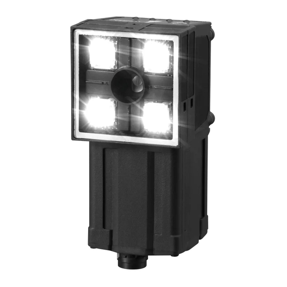
Page 37: Part Names And Functions
2-2 Part Names and Functions FQ2-S1 FQ2-S2 FQ2-S3 FQ2-S4 FQ2-CH FQ2-S@@@@@@-@@@ (Sensors with Built-in Lighting) FQ2-CH1@@@@@-M (Sensors with Built-in Lighting) Name Description Lighting LEDs for illumination Camera lens This lens can be focused. I/O Cable connector An FQ-WD or FQ-WU I/O Cable is used to connect the Sensor to the power supply and external I/O. - Page 38 FQ2-S@@-@@@ (Sensors with C-mounts) Bottom Sensor Mounted to Base Name Description C-mount lens mounting surface The C-mount lens and macro ring are attached here. Determine the appro- priate CCTV lens (C-mount lens) to use based on the field of view required for the size of the measurement object.
-
Page 39: Touch Finder
Touch Finder (11) (12) (10) Name Description Operation POWER Lights green when the Touch Finder is turned ON. indicators ERROR Lights red when an error occurs. 8-1 Error Histories: p.296 SD ACCESS Lights yellow when an SD card is inserted. Flashes yellow when the SD card is being accessed. -
Page 40: Sensor Data Units
Sensor Data Units Front Surface of Parallel Interface Back Surface of Parallel Interface RS-232C Interface Sensor Data Unit Sensor Data Unit Sensor Data Unit Name Description Sensor connector Connects to the FQ2-S3/S4/CH. Power supply and ground termi- Connects to the 24-V power source and the ground line. nal block Parallel I/O connector Connects to the I/O connector. -
Page 41: Installation
2-3 Installation FQ2-S1 FQ2-S2 FQ2-S3 FQ2-S4 FQ2-CH Installing the Sensor FQ2-S@@@@@@/FQ2-CH1@@@@@-M (Sensors with Built-in Lighting) Installation Procedure Align the tabs on one side of the Mounting Bracket with the slot on the Sensor. Mounting The FQ-XL Mounting Bracket can be attached to the back, Bracket side, or front of the Sensor. -
Page 42: Fq2-S@@-@@@ (Sensors With C-Mounts)
Important • There is a certain amount of deviation among Sensors in the center of the optical axis. For this reason, when install- ing the Sensor, check the center of the image and the field of view on the LCD monitor of the Touch Finder and in the PC Tool. -
Page 43: Lens Selection
Lens Selection Use the following optical diagrams to determine the Lens, camera installation distance, and detection range. Optical Diagrams The following values are estimates only. Adjustment is required after installing the camera. 3Z4S-LE SV-@@@@H High-resolution, Low-distortion Lenses 3Z4S-LE 10000 SV-0614H SV-0814H SV-1214H SV-1614H... - Page 44 The X axis in the above optical diagrams represent field of view (mm) . The Y axis represents the camera installation distance (mm) or WD (mm). These optical diagrams show the relationship between the detection range and installation distance for different CCTV Lenses. The values vary for each Lens. Pay close attention to the Lens that you are using when you refer to these optical diagrams.
- Page 45 3Z4S-LE SV-@@@@H High-resolution, Low-distortion Lenses Lens model Focal length Brightness Maximum out- Total length Filter size side diameter 3Z4S-LE SV-0614H 6.1 mm F1.4 42 mm 57.5 mm M40.5 P0.5 3Z4S-LE SV-0814H 8.0 mm F1.4 39 mm 52.5 mm M35.5 P0.5 3Z4S-LE SV-1214H 12.3 mm F1.4...
-
Page 46: Installation Precautions
Macro Rings Macro rings are inserted between the Lens and the camera to adjust the focus. You can use up to seven macro rings to achieve the required thickness. Macro ring Model Maximum out- Thickness side diameter 3Z4S-LE SV-EXR 31 mm 7-piece set Thickness: 0.5 mm... -
Page 47: Mounting To Din Track
Mounting to DIN Track Installation Procedure Press the slider on the Touch Finder to the top. Hook the clip at the top of the Touch Finder on to the DIN Track. Press the Touch Finder onto the DIN Track until the bottom clip clicks into place. -
Page 48: Using The Touch Finder As A Portable Device (With Battery)
Press the slider up on the Touch Finder. Create holes in the panel for mounting. Refer to the following page for hole dimensions. Dimensions: p.406 Connect the cable to the Touch Finder. Mount the Touch Finder with the Panel Mount Adapter from the front of the panel. -
Page 49: Mounting To Din Track
Connect the Neck Strap or Hand Strap to the Mini-strap. Mini-strap Neck Strap or Hand Strap Mounting Sensor Data Units Mounting to DIN Track Installation Procedure Lock the sliders at the top and bottom of the Sensor Data Unit. Press the slider on the Sensor Data Unit to the top. Hook the clip at the top of the Sensor Data Unit on to the DIN Track. -
Page 50: Wiring
OR31, the STGOUT (strobe trigger output), or an expression judgement from 0 to 31. Note The assignments of I/O signals can be changed. FQ2-S/CH Series User's Manual for Communications Settings (Cat. No. Z338) Section 2 Controlling Operation and Outputting Data with a Parallel Connection Wiring... -
Page 51: I/O Signal Circuit Diagrams
I/O Signal Circuit Diagrams Brown Power supply (24 VDC) Brown Power supply (24 VDC) Pink TRIG Load Black OUT0 (OR) Gray Orange OUT1 (BUSY) Green Light blue OUT2 (ERROR) White 24 VDC Purple Blue GND (0V) Yellow Pink TRIG 24 VDC Gray Green Light blue... - Page 52 For the I/O connector harness, use an FQ-VP1@@@ Parallel Cable for the FQ-SDU1 or a MIL-standard harness, such as the OMRON XZ2F. (The Cables are sold separately.) Pins 1 to 30 and pins 31 to 60 are for separate connectors. One FQ-VP1@@@ is required for each connector.
- Page 53 You can select whether to turn the external lighting ON (Positive) or OFF (Negative) when the signal turns ON. (The setting is called the strobe output polarity.) FQ2-S/CH Series User's Manual for Communications Settings (Cat. No. Z338) Section 2 Controlling Operation and Outputting Data with a Parallel Connection This control signal is used to turn ON external lighting when an image is taken.
- Page 54 For the I/O connector harness, use an FQ-VP2@@@ Parallel Cable for the FQ-SDU2 or a MIL-standard harness, such as the OMRON XZ2F. (The Cables are sold separately.) Pins 1 to 16 and pins 17 to 32 are for separate connectors. One FQ-VP2@@@ is required for each connector.
-
Page 55: Fq-Sdu20/Sdu25 Rs-232C Pin Signal Names
Pin numbers will depend on the external device being connected. Refer to the manual for the personal computer or PLC being connected. Use a compatible connector. • Recommended items Manufacturer Model Socket OMRON Corporation XM3D-0921 Hood OMRON Corporation XM2S-0913 FQ2-S/CH User’s Manual Wiring... - Page 56 Wiring The maximum cable length is 15m. • RS-232C Controller External device to be connected Signal name Pin No. Pin No. Signal name RS/CS control cannot be used. Use a shielded cable. Connection Method Align the connector with the socket and press it straight into place, then fix it with the screws on both sides of the connector.
- Page 57 I/O Signal Circuit Diagrams Output Circuit Input Circuit Input terminal 3 KΩ Output terminal Internal Load circuits COM_IN COM_OUT Output Circuit Input Circuit 3 KΩ Input terminal COM_OUT Internal circuits Load COM_IN Output terminal Important Preventing Chattering • The Sensor is equipped with an anti-chattering function, but if the chattering is 100 μs or longer, a faulty input may occur.
- Page 58 Wiring the Touch Finder Power Supply Wiring Connecting the Power Supply Loosen the two terminal screws using a Phillips screwdriver. Attach crimp terminals to the power lines. Secure the positive and negative lines as indicated 24 VDC using M3 screws. −...
-
Page 59: Charging The Battery
Charging the Battery This section describes how to charge and install the FQ2-D31 Battery and provides applicable precautions. Charge the Battery while it is attached to the Touch Finder. Use the AC adapter to charge the battery. Mounting the Battery in the Touch Finder Remove the screw from the battery cover on the top of the Touch Finder, slide the cover in the direction of the arrow, and open the battery cover. - Page 60 Important • If the Touch Finder (FQ2-D31) will be installed permanently or semi-permanently, remove the Battery (FQ-BAT1). If the rated temperature is exceeded with the Battery inserted, the protective circuit may activate and stop the Touch Finder. • The battery complies with the following recycling regulation. Japan Taiwan Li-ion00...
-
Page 61: Setting Up Ethernet
2-5 Setting Up Ethernet FQ2-S1 FQ2-S2 FQ2-S3 FQ2-S4 FQ2-CH Connecting to Sensors from the Touch Finder Configurations Consisting of Only Sensors and the Touch Finder When only Sensors and a Touch Finder are used, IP addresses are automatically assigned. No settings are required to use Ethernet. -
Page 62: Connecting To Sensors From External Devices Such As Plcs
Set the IP address and subnet mask according to the network where the external devices, such as PLCs, are connected. Note If you connect OMRON CS/CJ-series PLCs to the Ethernet, the following default IP addresses are assigned to the PLCs. • IP address: 192.168.250.node_address... - Page 63 Select [Internet Protocol Version 4 (TCP/IPv4)] in [Local Area Connection Properties], and click [Properties]. Select the Use the following IP address Option and en- ter the following IP address and subnet mask. • IP address: 10.5.5.101 • Subnet mask: 255.255.255.0 Click the [OK] Button.
- Page 64 Select the IP address to be used by PC Tool The computer IP address, subnet address, and default gateway that are used by the PC Tool are displayed. If multiple IP addresses (network cards) exist in the computer, the IP address to be used for the PC Tool can be selected.
-
Page 65: Taking Images
Taking Images 3-1 Selecting a Sensor for Configuration ......64 3-2 Setting Conditions for Taking Images ......65 3-3 Adjusting Image Quality . -
Page 66: Selecting A Sensor For Configuration
3-1 Selecting a Sensor for Configuration FQ2-S1 FQ2-S2 FQ2-S3 FQ2-S4 FQ2-CH If multiple Sensors are connected to a single Touch Finder or computer, a list of the Sensors that are connected is displayed by default. Use the following procedure to change to the Sensor to set up. −... -
Page 67: Setting Conditions For Taking Images
3-2 Setting Conditions for Taking Images FQ2-S1 FQ2-S2 FQ2-S3 FQ2-S4 FQ2-CH You can set the conditions for taking images to use in inspections. To enable accurate judgements, the following adjustments are made for the conditions for taking images and the images themselves. Taking Clear Images (Camera Setup) p. -
Page 68: Adjusting Image Quality
3-3 Adjusting Image Quality FQ2-S1 FQ2-S2 FQ2-S3 FQ2-S4 FQ2-CH Adjusting the Focus [Image] − [Camera setup] Display the Camera Setup Display. The focus can be seen as a numerical value. The higher the value, the better the focus. Focus Level Adjust the focus of the Sensor while checking the im- Focus adjustment screw age and focus value on the Touch Finder. -
Page 69: Adjusting Image Brightness With External Lighting
If a Data Unit is connected, you can change the output time of the strobe trigger signal (STGOUT) to adjust the brightness. FQ2-S/CH Series User's Manual for Communications Settings (Cat. No. Z338) Section 2 Controlling Operation and Outputting Data with a Parallel Connection Adjusting the Brightness You can adjust the shutter speed/gain or the brightness to make images brighter. - Page 70 When HDR Is OFF The brightness of the image is adjusted by adjusting the shutter speed. If the brightness cannot be improved by adjusting the shutter speed, the gain is adjusted. Relationship between the Shutter Speed/Gain and the Image Brightness (For FQ2-S3/S4 series) Dark Bright Brightness of image...
- Page 71 Parameter Setting Description Shutter speed Range: If the shutter speed is slow, the image will be For FQ2-S3@-@@@, FQ2-S4@-@@@ bright. If the shutter speed is fast, the image 1/1 to 1/4,155 will be dark. For FQ2-S3@@@@-08@, FQ2-S4@@@@-08@ Built-in lighting off: 1/1 to 1/4,155 Built-in lighting on: 1/250 to 1/60,000 (control by light- ing emission time) For FQ2-S1@@@@@, FQ2-S2@@@@@, FQ2-...
-
Page 72: Taking Clear Images Of Moving Objects
Taking Clear Images of Moving Objects For quick moving objects, the effect of blurring can be reduced by decreasing the shutter speed. In HDR Mode, set the brightness value to a low setting. • Relationship between Shutter Speed and the Brightness Adjustment Value in HDR Mode Slow Fast Moving speed... - Page 73 Observe the following precautions. • Use the HDR function only for objects that are not moving to avoid image blurring. Several images are taken with different shutter speeds and combined. If the object moves while the image is being taken, the image will become blurred. •...
-
Page 74: Adjusting The Colors Of The Image (White Balance) (Only For Sensors With Color Cameras)
Adjusting the Colors of the Image (White Balance) (Only for Sensors with Color Cameras) If external lighting is used, the image may appear as having different colors than the actual object. If this is the case, adjust the white balance. If the lighting built in to the Sensor is used, the white balance is already adjusted. -
Page 75: Adjusting The Timing Of Taking Images
3-4 Adjusting the Timing of Taking Images FQ2-S1 FQ2-S2 FQ2-S3 FQ2-S4 FQ2-CH Delaying the Image Capture Timing from the Trigger Input If the measurement object is moving, the position in the image of the feature that is to be measured will depend on the timing of the trigger signal. -
Page 76: Adjusting External Lighting Timing
If a Sensor Data Unit is connected, you can change the output time of the strobe trigger signal (STGOUT) to adjust the timing of the external lighting. FQ2-S/CH Series User's Manual for Communications Settings (Cat. No. Z338) Section 2 Controlling Operation and Outputting Data with a Parallel Connection [Image] −... -
Page 77: Adjusting The Images That Were Taken
3-5 Adjusting the Images That Were Taken FQ2-S1 FQ2-S2 FQ2-S3 FQ2-S4 FQ2-CH Image Adjustment You can adjust the image that is taken by the Sensor to make it easy to measure. There are mainly the following two types of items that you can use to adjust the image. •... -
Page 78: Filtering The Images (Filter Items)
Note Specify the Camera image for the first filter item for image processing. If you execute more than one filter item for the image, set the source image for the other filter items to the previous image. Also, you can perform image processing with filter items only to enable processing with position compensation items. - Page 79 Selected filter item Description Background Suppression Extracts a specific range of brightness to increase the image contrast and suppress the unnecessary background. Example: Increasing Contrast → Any areas that are outside of the specified range of brightness are removed as the background. Also, the brightness within the specified range is converted to 256 levels to enhance the contrast.
- Page 80 Setting the Region to Filter You can specify the region to which to apply the filter. This setting does not exist in the Color Gray Filter item. [Image] − [Image adjustment] − [Add filter] − (Filter item to select) − Press [ [Filter region] on the right of the display.
- Page 81 • RGB Parameter Setting Description Filter settings • Red filter (default) These filters achieve the same effect as when using the selected optical • Green filter filter. • Blue filter • Cyan filter • Magenta filter • Yellow filter • Brgt.F (brightness filter) (R+G+B) •...
- Page 82 with the Background Suppression item. • Enhancing the Contrast of a Specific Area You specify the location on the image to enhance the contrast. [Image] − [Image adjustment] − [Background Suppression] − [Modify] − Press [ [Suppression level] on the right of the display.
-
Page 83: Compensating For Position Offset (Position Compensation Items)
Parameter Setting Description Common (common Range: 0 to 255 Set the upper and lower limit values of the background suppression level. RGB setting) Defaults: Lower limit: 0, Upper limit: The same limits will be used for all RGB colors. The range from the specified lower to upper limits is converted to 0 to 255. - Page 84 • Features of the Position Compensation Items Edge Position Compensation The position is corrected in either the X or Y direction. The position is offset in only one direction. Edge Position Compensation: p. 88 Two-edge Position Compensation The position is corrected at the The position is offset in same time in both the X and Y two directions.
- Page 85 Applying the Results of Position Compensation You can apply the results of position compensation either to the Camera image or to the previous image from before position compensation was applied. If you apply the results of position compensation to the Camera image, only the position information from position compensation is applied to the image to be measured.
- Page 86 • Using Filter Items for Processing with Position Compensation Items To more effectively perform position compensation, filter items can be used to create an image specifically for position compensation and then apply only the results of processing the position compensation to the image that will be measured.
- Page 87 − Press [Model] [Shape Sear. pos. comp.] Make any detailed settings as required for the posi- tion compensation processing. Refer to Detailed Settings for Shape Search Position Compensation, below. Press [OK]. Press [Back]. • Detailed Settings for Shape Search Position Compensation The settings for the Shape Search Position Compensation item are almost the same as those for the Shape Search II inspection item.
-
Page 88: Search Position Compensation
Expression text string Data name Description Data range −99,999.9999 to 99,999.9999 Position X This is the X coordinate of the position where the model was found. −99,999.9999 to 99,999.9999 Position Y This is the Y coordinate of the position where the model was found. −180 to 180 Angle This is the angle at which the model... - Page 89 • Detailed Settings for Search Position Compensation The settings for the Search Position Compensation item are almost the same as those for the Search inspection item. (The [Multi-point output] and model parameter settings of the Search inspection item are not included in the Search Position Compensation settings.) Make the settings for teaching and the judgement conditions in the same way as for the Search item.
- Page 90 • Measurement Data That Can Be Logged The values below can be logged as measurement data. Parameter Setting Description −2: No judgement (not measured), Judgement This is the judgement result. 0: Judgement is OK, −1: Judgement is NG, −15: Out of range error −99,999.9999 to 99,999.9999 Scroll X This is the amount of position compensation for the X coordinate.
- Page 91 • Source Image You can select the image to which to apply the results of position compensation processing. Applying the Results of Position Compensation: p. 83 • Interpolation You can select the precision of position compensation. If you select [Bilinear], the precision of position compensation will increase. [Image] −...
- Page 92 Two-edge Position Compensation This position compensation item detects edges in two directions. If the specified color is detected (or the specified density is detected for a Sensor with a Monochrome Camera), it is recognized as an edge. When an edge is recognized, the image is adjusted so that the edge appears at the position it was in when it was registered.
- Page 93 • Teaching Set the measurement regions and measurement directions for both edge 0 and edge 1. [Image] − [Image adjustment] − [2Edge position comp.] − [Modify] − [Basic] Press [Teach]. Place the object that is to be used as the measure- ment reference in front of the camera.
- Page 94 • Measurement Data That Can Be Used for External Outputs and Calculations The following values can be used as measurement data and output to external devices via Ethernet or used in calculations. Expression text string Data name Description Data range −2: No judgement (not measured), Judgement This is the judgement result.
- Page 95 Two-edge Midpoint Compensation This position compensation item detects edges in two directions. If the specified color is detected (or the specified density is detected for a Sensor with a Monochrome Camera), it is recognized as an edge. Two edge positions are detected. The image is adjusted so that the coordinates of the midpoint position of a line that connects the two detected edge positions matches the position when the edges were registered.
- Page 96 • Source Image You can select the image to which to apply the results of position compensation processing. Applying the Results of Position Compensation: p. 83 • Interpolation You can select the precision of position compensation. If you select [Bilinear], the precision of position compensation will increase. [Image] −...
- Page 97 • Measurement Data That Can Be Logged The values below can be logged as measurement data. Parameter Setting Description −2: No judgement (not measured), Judgement This is the judgement result. 0: Judgement is OK, −1: Judgement is NG, −15: Out of range error −99,999.9999 to 99,999.9999 Scroll X This is the amount of position compensation for the X coordinate.
- Page 98 • Detailed Settings for Edge Rotation Position Compensation The settings for the Edge Rotation Position Compensation item are almost the same as those for the Edge Position inspection item. Make the settings in the same way as for the Edge Position inspection item. ( 4-11 Inspecting with the Edge Position Inspection Item: p.
- Page 99 Expression text string Data name Description Data range −180 to 180 Angle (edge angle) This is the measured angle. −99,999.9999 to 99,999.9999 Edg0 ref. pos. (edge 0 This is the X coordinate of the edge 0 reference position X) position when it was registered. −99,999.9999 to 99,999.9999 Edg0 ref.
- Page 100 MEMO Adjusting the Images That Were Taken FQ2-S/CH User’s Manual...
-
Page 101: Setting Up Inspections
Setting Up Inspections 4-1 Inspection Item Selection Guide ......100 4-2 Setup Procedure for Inspection Items......103 4-3 Configuring Inspection Items. -
Page 102: Inspection Item Selection Guide
FQ2-S1 Shape p. 156 Search II FQ2-S2 FQ2-S3 FQ2-S4 Detecting positions with patterns Measurement objects of the same color and pattern can be Search p. 146 FQ2-S1 detected. FQ2-S2 FQ2-S3 OMRON OMRON FQ2-S4 Inspection Item Selection Guide FQ2-S/CH User’s Manual... - Page 103 Inspection Example Inspection Compati- Refer- items used ble models ence Dividing the measurement area Judging minute differences in Sensitive p. 164 FQ2-S1 and judging according to shapes printed labels Search for each division FQ2-S2 LED RADIATION DO NOT STARE INTO BEAM FQ2-S3 Max.65mW 400-700nm...
- Page 104 Inspection Example Inspection Compati- Refer- items used ble models ence Judging according to shapes Judging the number of labels Labeling p. 202 FQ2-S1 and quantities FQ2-S2 FQ2-S3 FQ2-S4 Inspection Item Selection Guide FQ2-S/CH User’s Manual...
-
Page 105: Setup Procedure For Inspection Items
4-2 Setup Procedure for Inspection Items FQ2-S1 FQ2-S2 FQ2-S3 FQ2-S4 FQ2-CH The basic steps for setting up inspection items are shown below. Configuring Inspection Items Step 1 Teaching Step 2 Setting Judgement Parameters Step 3 If measurements are unstable Setting Detailed Items Step 4 Re-teaching Step 5... -
Page 106: Configuring Inspection Items
4-3 Configuring Inspection Items FQ2-S1 FQ2-S2 FQ2-S3 FQ2-S4 FQ2-CH Adding New Inspection Items Press [Inspect] − [Inspection]. Press an unused inspection item number. Press [Add item.] on the menu. Select an inspection item, such as [Search]. When registering multiple inspection items, press the inspection item number after 1.--- and set it in the same way. -
Page 107: Modifying Existing Inspection Items
Modifying Existing Inspection Items Press the number of the inspection item to be set. Press [Modify] on the menu. Deleting Inspection Items Press the number of the inspection item to be delet- Press [Delete] on the menu. Note Executing Similar Measurements in Different Places →... -
Page 108: Reading And Verifying Character Strings
4-4 Reading and Verifying Character Strings FQ2-S4 FQ2-CH Character String Recognition Character recognition is used to read characters in input images as character information based on font information that is registered in the Sensor in advance. The characters that were read can be output to an external device. -
Page 109: Setup Procedure For Character Recognition
Setup Procedure for Character Recognition The setup for character recognition is performed in the following order. The basic settings to recognize characters are made. • Character format (number of characters, alphanumeric Teaching characters or symbols, etc.) • Measurement region • Detailed parameters to recognize characters (These are set automatically.) Settings are made to check whether the characters that were read from the workpiece were recognized correctly. - Page 110 Step 2 Teaching For teaching, you specify the measurement region and the format of the characters to read (number of characters, alphanumeric characters or symbols, etc.). Detailed parameters to recognize the characters will be set automatically. Also, you can register the characters that are actually read when teaching as a verification condition in the master data.
- Page 111 Item Description Limits to the character • Each line can have a maximum of 32 characters. There can be a maximum of four lines. format string • Characters must be input from line 1. (You cannot skip line 1 and set the character format string starting with line 2.) If you leave any line blank, the setting for the next line will be moved up to fill it.
- Page 112 Note You can use on the right of the display to access the following menu commands to change the following settings [Insp. region] : You can change the measurement region for OCR. [Format] : You can change the setting of the character format. [Camera setup] : You can adjust the Camera focus, brightness, and other factors to input a better image.
- Page 113 Note You can specify whether to reflect the judgement result of the judgement conditions for character recognition in the overall judgement. (The default is to reflect them.) − − − − − − [Inspect] [Inspection] [Add item.] [OCR] [Details] Tab Page [Output parameter] [Reflect] Step 4 Setting the Verification Conditions...
- Page 114 Note You can set letters, numbers, symbols, and the following wild- cards: * and ?. *: A wildcard for a character string of 0 or more characters ?: A wildcard for one character (alphabetic or numeric) [Item ref.]: Select this item to use the immediately pre- ceding read results as the verification charac- ter string.
-
Page 115: Setting The Measurement Parameters
Parameter Setting Description Verif. master data OFF (default) Sets whether to verify the read character string against a character string that All master data is registered in the master data. Master data 0 to 31 To verify the read character string against the master data, select the character string to use for verification. -
Page 116: Changing The Output Code For Errors (Default: Ng)
Parameters That Are Automatically Set during Teaching The following measurement parameters are automatically set when teaching is performed. • Character color • Printing type • Dot ver. interval • Dot hor. interval • Char. thick. th. • Noise filter size •... - Page 117 Press [Modify] on the menu. Press [Add]. You can register up to 10 versions of each character (0-9 and A-Z). − [Extraction reg.] on the right of the dis- Press play. Specify the region to extract and press [OK]. The measurement region can contain character strings on up to four lines.
- Page 118 The extracted characters will be displayed on the up- per left of the display. Press [OK] to register the characters. The characters are registered for the corresponding character type. Error Messages during Registration • Failed to register data. Character format is wrong. The format or the number of characters did not match between the read character string and the registered charac- ter string.
- Page 119 The registered characters will be displayed. Deleting Registered Characters Select the character that you want to delete in the customized dictionary registration display. Press [Delete]. Press the [Yes] Button. Changing the Measurement Parameters On the right of the display to add characters, press −...
- Page 120 Press a line to enter the character format for that line from the software keyboard that is displayed. Enter the character format for each line. Setting Dictionary Parameters − − − − [Inspect] [Inspection] [Add item.] [OCR] [Details] Tab Page Press [Dictionary param.].
-
Page 121: Outputting Read Characters To An External Device
Vision Sensor FQ2-S/CH Series User's Manual for Communications Settings (Cat. No. Z338) • Section 2 Controlling Operation and Outputting Data with a Parallel Connection •... -
Page 122: Measurement Data That Can Be Logged For Ocr
Measurement Data That Can Be Logged for OCR Parameter Setting Description −2: Not measured, Judgement This is the judgement result. 0: Judgement is OK, −1: Judgement is NG, −16: Measurement timeout error, −17: Format not entered error Similarity 0 to 100 This is the lowest similarity of the read characters. -
Page 123: Reading Bar Codes
4-5 Reading Bar Codes FQ2-S4 Bar Codes You can read barcodes. You can also verify if the character string that was read from the barcode matches a registered character string. You can output the result of reading a barcode and the verification result to an external device. The following ten code types can be read. -
Page 124: Setup Procedure For Bar Code
Setup Procedure for Bar Code Step 1 Selecting the Inspection Item − [Inspect] [Inspection] Press an unused inspection item number and press [Add item.]. Press [Bar code]. 4-3 Configuring Inspection Items: p. 104 Note Drag the arrow ( ) at the bottom of the menu to display all of the inspection items. - Page 125 Note You can use the menu commands that are displayed for at the right of the display to adjust the settings that resulted from teaching. [Insp. region]: You can change the measurement region. [Camara setup]: You can adjust the Camera focus, brightness, and other factors to input a better image. Adjusting Image Quality: p.
- Page 126 Note Check the table of ASCII characters to see what characters can be registered. You cannot enter two-byte characters, one-byte Kana characters, and control codes. You can use the following characters as wildcards. *: A wildcard for a character string of 0 or more characters ?: A wildcard for one character ASCII code table: p.
-
Page 127: Reflect In Total Judgement
Press [Back]. Note ASCII code table The following table shows the ASCII codes that can be used for manual registration of master data and also for registering characters of Limits. Upper 4 bits Lower 4 bits Reflect in Total Judgement You can specify whether to reflect the verification result of a barcode inspection item in the overall judgement. -
Page 128: Changing The Character String That Is Output For Read Errors
Setup Item Setting Value Description Code type JAN/EAN/UPC (default Selects the type of barcode to be read. value) Code39 Codebar Code93 Code128/GS1-128 GS1 DataBar Pharmacode Code color Black (default value) Sets the color of the code to be read. White Composite codes on/off No (default value) Sets whether or not to support composite codes. -
Page 129: Unstable Reading Results
Refer to the description for the communications format for the setting procedure and output specifications to output the character string. Vision Sensor FQ2-S/CH Series User's Manual for Communications Settings (Cat. No. Z338) • Section 2 Controlling Operation and Outputting Data with a Parallel Connection •... -
Page 130: Measurement Data That Can Be Logged (Bar Code)
Measurement Data That Can Be Logged (Bar Code) The following values can be logged as measurement data. Measured item Range of value Description −2: No judgement (not measured), Judgement This is the judgement result from the measurements. 0: Judgement is OK, −1: Judgement is NG, −16: Measurement timeout error Num. -
Page 131: Reading 2D-Codes
4-6 Reading 2D-codes FQ2-S4 2D-codes You can read 2D codes. You can also verify whether the character string that was read from the 2D code matches a registered character string. You can output the result of reading a 2D code and the verification result to an external device. -
Page 132: Setup Procedure For 2D-Code
Setup Procedure for 2D-code Step 1 Selecting the Inspection Item [Inspect] − [Inspection] Press an unused inspection item number and press [Add item.]. Press [2D-code]. 4-3 Configuring Inspection Items: p. 104 Note Drag the arrow ( ) at the bottom of the menu to display all of the inspection items. - Page 133 Note You can use the menu commands that are displayed for at the right of the display to adjust the settings that resulted from teaching. [Insp. region]: You can change the measurement region. [Camera setup]: You can adjust the Camera focus, brightness, and other factors to input a better image. Adjusting Image Quality: p.
- Page 134 [Item ref.]: Select this item to use the immediately pre- ceding read results as the verification charac- ter string. The following inspection items can be used as references: Bar code, 2D-code, 2D-code (DPM), and OCR. You cannot refer- ence an inspection item at an item number that is after the item number of the inspection item that you are editing.
-
Page 135: Reflect In Total Judgement
Note ASCII code table The following table shows the ASCII codes that can be used for manual registration of master data and also for registering characters of Limits. Upper 4 bits Lower 4 bits Reflect in Total Judgement You can specify whether to reflect the verification result of a 2D code inspection item in the overall judgement. (The default setting is [Yes].) −... -
Page 136: Outputting Read Characters To An External Device
Refer to the description for the communications format for the setting procedure and output specifications to output the character string. Vision Sensor FQ2-S/CH Series User's Manual for Communications Settings (Cat. No. Z338) • Section 2 Controlling Operation and Outputting Data with a Parallel Connection •... -
Page 137: Changing The Items That Are Displayed On The Test Measurement And Run Display
Changing the Items That Are Displayed on the Test Measurement and Run Display To change the items that are displayed on the test measurement and run display, press [Test] − [Continuous test] − and then use − [Display setting] on the Test Display. Display setting Description Num. -
Page 138: Errors
Errors Errors in Teaching If 2D-codes cannot be read during an automatic registration, a teaching error message is displayed. The reading may be unstable due to low contrast.Adjust the brightness to improve the contrast of the 2D-code. Adjusting the Brightness: p. 67 Reading 2D-codes FQ2-S/CH User’s Manual... -
Page 139: Reading 2D Codes (Dpm)
4-7 Reading 2D Codes (DPM) FQ2-S4 2D Codes (DPM) You can read DPM (direct part marking) 2D codes. You can also verify whether the character string that was read from the 2D code matches a registered character string. You can output the result of reading a 2D code and the verification result to an external device. The scan result and verification result can be externally output. - Page 140 Step 2 Teaching For teaching, the region to measure and the 2D code within that region are set as read conditions. You can also register the contents that was read from the 2D code as a verification condition in the master data. Step 4 Setting the Verification Conditions: p.
- Page 141 Note You can use the menu commands that are displayed for at the right of the display to adjust the settings that resulted from teaching. [Insp. region]: You can change the measurement region. [Camera setup]: You can adjust the Camera focus, brightness, and other factors to input a better image. Adjusting Image Quality: p.
- Page 142 Note You can specify whether to reflect the judgement result of the judgement conditions for character recognition in the overall judgement. (The default is to reflect them.) [Inspect] − [Inspection] − [Add item.] − [2D-code (DPM)] − [Details] Tab Page − [Output parameter] −...
- Page 143 You can use any of the following three methods to register character strings in the master data from the menu display. [Auto]: Registers a character string from an actual 2D code in the master data. The procedure is es- sentially the same as the procedure for teach- ing in step 2.
- Page 144 Parameter Setting Description Partial verif. on/off No (default value) The number of digits in the read results to be verified with the master data can be limited. When [Partial verification] is set to ON, set the first and last compared digit positions. Up to 32 characters can be set as the number of digits.
-
Page 145: Detailed Parameters
Detailed Parameters With the default settings, all of the parameters are set automatically. If scanning cannot be performed because the code is different or otherwise, set the measurement parameters manually and execute teaching. [Inspect] - [Inspection] - [Add item] - [2D-code (DPM)] - [Details] Tab Page - [Meas. Parameter] Measurement Parameters Parameter Setting... -
Page 146: Outputting Read Characters To An External Device
Refer to the description for the communications format for the setting procedure and output specifications to output the character string. Vision Sensor FQ2-S/CH Series User's Manual for Communications Settings (Cat. No. Z338) • Section 2 EtherNet/IP • Section 3 PLC Link •... -
Page 147: Measurement Data That Can Be Used For External Outputs And Calculations
Measurement Data That Can Be Used for External Outputs and Calculations Expression text Data name Description Data range string −2: No judgment (not measured), Judgment This is the judgment result. 0: Judgment is OK, −1: Judgment is NG, −16: Measurement timeout error −2: Verification OFF, Index The verification result (master data No.) is... -
Page 148: Inspecting With The Search Inspection Item
4-8 Inspecting with the Search Inspection Item FQ2-S1 FQ2-S2 FQ2-S3 FQ2-S4 Search Inspection Item This inspection item is used to perform inspections for shapes or for presence. The image pattern that is to be measured is registered in advance and measurements are performed to see if the pattern is present or if the shape is different. - Page 149 Step 2 Teaching Teaching means to store the region and partial image as reference data for the measurement. − [Add item.] − [Search] − [Settings] Tab Page − [Inspection] [Inspect] Press [Teach]. Drag a corner to Drag the rectangle size the rectangle. to move it.
-
Page 150: Increasing Measurement Position Accuracy
Parameter Setting Description Correlation Range: 0 to 100 Adjust the upper and lower limits of the correlation for an OK judge- Defaults: Lower limit: 60, Upper limit: 100 ment. Range: −99,999.9999 to 99,999.9999 Position X Adjust the upper and lower limits of measurement position X for an Defaults: Lower limit: −99,999.9999, OK judgement. -
Page 151: Select The Results To Output
Selection item Setting Description Sorting method Corr. ascending order (ascending order of correlation Sorts the results in order from the smallest correlation value) to the largest. Corr. descending order (descending order of correlation Sorts the results in order from the largest correlation to value) (default) the smallest. -
Page 152: Unstable Search Results
Unstable Search Results Inclined Measurement Objects Adjust the [Angle range] parameter to increase the range in which a search is made for the model. The Search inspection item judges whether an image is OK or NG according to the correlation with a previously registered image pattern. -
Page 153: Increasing Processing Speed
Increasing Processing Speed The following two methods can be used to reduce processing time. • Reduce the range in which a search is performed for the model. Changing the measurement region: p. 153 • Reduce the angle range setting. Adjust the [Angle range] parameter to reduce the range in which a search for the model is performed. Setting the angle range: p. - Page 154 Press [Add] in [ Press the shape of the region that you want to use. Draw the region. Press [OK]. Note Up to 8 shapes can be combined to create a region for one model. Masking Parts of the Model The model registration region can be formed freely by combining enabled and disabled regions.
- Page 155 Fine-tuning the Position of the Region This section describes the console which is useful to fine-tune the position of the measurement region or the model registration region in 1-pixel increments. − [Search] − [Modify] − [Settings] Tab Page − [Teach] − [ ] − [Model −...
- Page 156 Changing Output Coordinate Positions You can specify which part of the model to detect as coordinates during inspections. Normally, the center position of the registered model is used as the detection point. [Inspect] − [Inspection] − [Search] − [Modify] − [Settings] Tab Page − [Teach] − [ ] − [Detection point] Use one of the following methods to move the cross Drag the cross cursor.
-
Page 157: Errors
Measurement Data That Can Be Logged The following values can be logged as measurement data. Parameter Range of value Description Judgement 0: Judgement is OK This is the measurement judgement results. −1: Judgement is NG −13: Teaching not performed error −14: Figure not registered error −15: Out of range error Correlation... -
Page 158: Inspecting With The Shape Search Ii Inspection Item
4-9 Inspecting with the Shape Search II Inspection Item FQ2-S1 FQ2-S2 FQ2-S3 FQ2-S4 Shape Search II Inspection Item This inspection item is used to search for the portion of the input image that most closely resembles an image pattern that is called a model. The model is registered in advance based on a characteristic feature of the measurement object. - Page 159 Step 2 Teaching Teaching means to store the region and partial image as reference data for the measurement. − [Add item.] − [Shape Search II] − [Settings] Tab Page − [Inspection] [Inspect] Press [Teach]. Drag a corner to Drag the rectangle size the rectangle.
-
Page 160: Obtaining Multiple Results Simultaneously
Parameter Setting Description Correlation Range: 0 to 100 Adjust the upper and lower limits of the correlation for an OK judge- Defaults: Lower limit: 60, Upper limit: 100 ment. Range: −99,999.9999 to 99,999.9999 Position X Adjust the upper and lower limits of measurement position X for an Defaults: Lower limit: −99,999.9999, OK judgement. -
Page 161: Select The Results To Output
Select the Results to Output You can use multiple conditions to determine which results to output from all the objects detected with a correlation at the candidate level or higher. Only the results that meet all the specified conditions are output. [Inspect] −... -
Page 162: Unstable Shape Search Ii Results
Unstable Shape Search II Results Inclined Measurement Objects Adjust the [Angle range] parameter to increase the range in which a search is made for the model. The Shape Search II inspection item judges whether an image is OK or NG according to the correlation with a previously registered image pattern. -
Page 163: Increasing Processing Speed
Increasing Processing Speed The following two methods can be used to reduce processing time. • Reduce the range in which a shape search II is performed for the model. Changing the measurement region: p. 153 • Reduce the angle range setting. Adjust the [Angle range] parameter to reduce the range in which a shape search II for the model is performed. - Page 164 Measurement Data That Can Be Used for External Outputs and Calculations The following values can be used as measurement data and output to external devices via the Ethernet or used in calculations. Expression text string Data name Description Data range −2: No judgement (not measured), Judgement This is the judgement result.
-
Page 165: Errors
Errors Errors in Teaching A teaching error message will appear if the contrast of the image within the model registration region is too low. Select a region with a larger contrast between light and dark areas compared to the region that was registered as the model and re-register it as the model. -
Page 166: Inspecting With The Sensitive Search Inspection Item
4-10 Inspecting with the Sensitive Search Inspection Item FQ2-S1 FQ2-S2 FQ2-S3 FQ2-S4 Sensitive Search Inspection Item This inspection item automatically divides the registered model into smaller areas and performs matching for details. The lowest correlation for all of the divisions is output. A sensitive search is suitable when the differences between the model image and measurement image are too small to produce differences in correlations with a normal search. - Page 167 Step 2 Teaching Teaching means to store the region and partial image as reference data for the measurement. − [Add item.] − [Sensitive Search] − [Settings] Tab Page − [Inspection] [Inspect] Press [Teach]. Drag the rectangle Drag a corner to to move it.
-
Page 168: Reflect In Total Judgement
Parameter Setting Description Density devi- • Color image Set the density difference range that is to be judged as OK. The value ation will increase for larger percentages of areas with no pattern. This param- Range: 0 to 221 eter is valid when setting a plain inspection area for a divided model. Defaults: Lower limit: 0, Upper limit: 221 •... -
Page 169: Select The Results To Output
Select the Results to Output Only objects with a correlation that is higher than the specified candidate level are output. [Inspect] − [Inspection] − [Sensitive Search] − [Modify] − [Details] Tab Page − [Meas. Parameter] Press [Candidate level] and adjust the candidate lev- el so that only objects higher than a certain correla- tion are detected. -
Page 170: Increasing Processing Speed
Press [Angle range] and set the following range. Parameter Setting Description Range: −180 to 180 Angle range A search is performed within the set angle range. Default: Lower limit: −180, The larger the angle range, the longer the processing time. Upper limit: 180 Important If you change the angle range, perform teaching again. -
Page 171: Editing The Model Regions And Measurement Region
Editing the Model Regions and Measurement Region Changing the Model Regions This section describes how to edit the model regions. You can edit the model region in the same way as for a search region. Changing the Model Registration Region to a Shape Other Than a Rectangle: p. - Page 172 Measurement Data That Can Be Used for External Outputs and Calculations The following values can be used as measurement data and output to external devices via the Ethernet or used in calculations. Expression text string Data name Description Data range −2: No judgement (not measured), Judgement This is the judgement result of the...
-
Page 173: Errors
Measurement Data That Can Be Logged The following values can be logged as measurement data. Parameter Range of value Description −2: No judgement (not measured), Judgement This is the judgement result of the sensitive search. 0: Judgement is OK, −1: Judgement is NG Correlation 0 to 100 Correlation... -
Page 174: Inspecting With The Edge Position Inspection Item
4-11 Inspecting with the Edge Position Inspection Item FQ2-S1 FQ2-S2 FQ2-S3 FQ2-S4 Edge Position This inspection item is used to inspect positions. For example, it can be used to see if a label is attached at the correct position or if a product is set in the correct position. Places where the color changes greatly are called edges. - Page 175 Step 2 Teaching Teaching means to store the region and the edge position in the region as reference data for the measurement. − [Add item.] − [Edge Position] − [Settings] Tab Page − [Inspection] [Inspect] Press [Teach]. The arrow in the middle shows the direction for detecting an edge.
-
Page 176: Reflect In Total Judgement
Note • You can change the output form for each measurement value to one of the following settings. − [Result type] on the right of the display. Press Absolute value (default): The measured coordinates are output as absolute values. Relative value: The difference from the reference value is output. Reflect in Total Judgement You can specify whether to reflect the judgement results of an inspection item in the overall judgement. - Page 177 Note Edge Level • When measuring by relative value (%) of color difference width An edge is detected in the following way. 1. The color change distribution of the entire measurement region is determined. 2. The minimum color change is 0%. The maximum color change is 100%. 3.
- Page 178 Note Noise threshold The maximum and minimum color deviations and densities within the edge detection region are determined. If the difference is less than the noise threshold, it is assumed that there are no edges. Normally there is no problem with the default value of 10, but if noise is mistakenly detected as an edge, make this value higher. •...
- Page 179 Undesired Edge Position Is Automatically Detected When Teaching (Sensors with Color Cameras Only) Manually set the color of the edge that you want to detect. [Edge Position] − [Modify] − [Inspection] − − − [Inspect] [Settings] Tab Page [Teach] Press [ ] –...
-
Page 180: Increasing Processing Speed For Edge Position
Increasing Processing Speed for Edge Position Make the measurement region smaller to reduce the processing time. Changing the measurement region: p. 153 Measurement Data That Can Be Used for External Outputs and Calculations The following values can be used as measurement data and output to external devices via the Ethernet or used in calculations. -
Page 181: Errors
Errors Errors in Teaching A teaching error message will appear if the edge position cannot be detected when teaching. Perform the following. • If the color of the measurement object has changed from the specified color, set the color again and try teaching again. -
Page 182: Inspecting With The Edge Width Inspection Item
4-12 Inspecting with the Edge Width Inspection Item FQ2-S1 FQ2-S2 FQ2-S3 FQ2-S4 Edge Width Inspection Item This inspection item is used to measure dimensions. Places where the color changes greatly are called edges. The distance between two edges is called the edge width. Sample Settings Sample Measurement Edges are searched from... - Page 183 Step 2 Teaching Teaching means to store the region and the edge width in the region as reference data for the measurement. − [Add item.] − [Edge Width] − [Settings] Tab Page − [Inspection] [Inspect] Press [Teach]. The middle arrow is the direction for detecting an edge.
-
Page 184: Changing Edge Detection Conditions (Sensors With Monochrome Cameras Only)
Press [OK] to enter the value. Item Parameter Setting Description Judgement parameters Edge width (edge in When the result type is set to abso- Set the upper and lower limits of the width) lute value reference width for an OK judgement. Range: 0.0000 to 99,999.999 Defaults: Upper limit: 99,999.999, Lower limit: 0.0000... -
Page 185: Measurement Data That Can Be Used For External Outputs And Calculations
Measurement Data That Can Be Used for External Outputs and Calculations The following values can be output to external devices or used in calculations as measurement data. Expression text string Data name Description Data range −2: No judgement (not measured), Judgement This is the judgement result. - Page 186 Edge Not Found The measured edge width will be 0. Perform the following. • If a color was specified, make sure the color of the measurement object has not changed from the specified color. • Set the color again if necessary. •...
-
Page 187: Inspecting With The Edge Pitch Inspection Item
4-13 Inspecting with the Edge Pitch Inspection Item FQ2-S1 FQ2-S2 FQ2-S3 FQ2-S4 Edge Pitch Inspection Item This inspection item is used to detect edges through changes in brightness within a region. Edges of the specified color in one measurement area are found and the number objects, object width, and pitch are output. Sample Settings Sample Measurement Measurement region... - Page 188 Step 2 Teaching Teaching means to store the region as reference data for the measurement. − [Add item.] − [Edge Pitch] − [Settings] Tab Page − [Inspection] [Inspect] Press [Teach]. Place the object that is to be used as the measure- The middle arrow is the direction for detecting an edge.
-
Page 189: Changing Edge Detection Conditions (Sensors With Monochrome Cameras Only)
Item Parameter Setting Description Judgement Parameter Edge pitch Range: 0 to 1000 Set the range that is to be judged OK Defaults: Lower limit: 0, for each parameter. Upper limit: 1000 Average pitch Range: 0.0000 to 99,999.9999 Defaults: Lower limit: 0.0000, Upper limit: 99,999.9999 Max. -
Page 190: Measurement Data That Can Be Used For External Outputs And Calculations
Measurement Data That Can Be Used for External Outputs and Calculations The following values can be output to external devices or used in calculations as measurement data. Expression text string Data name Description Data range −2: No judgement (not measured), Judgement This is the judgement result. -
Page 191: Errors
Errors Errors in Teaching A teaching error message will appear if the edge pitch cannot be detected when teaching. Perform the following. • If the color of the measurement object has changed from the specified color, set the color again and try teaching again. -
Page 192: Inspecting With Color Data Inspection Item
4-14 Inspecting with Color Data Inspection Item FQ2-S1 FQ2-S2 FQ2-S3 FQ2-S4 Color Data Inspection Item This inspection item is used to perform inspections for foreign matter with a different color or for presence. The region is set for a portion of the image with the color that is to be measured. This region is called the measurement region. - Page 193 Step 2 Teaching Teaching means to store the region and the average color in the region as reference data for the measurement. − [Add item.] − [Color Data] − [Settings] Tab Page − [Inspection] [Inspect] Press [Teach]. Drag the rectangle to move it. Drag a corner to size the rectangle.
-
Page 194: Reflect In Total Judgement
• Sensors with Color Cameras Only Item Parameter Setting Description Judgement Color difference 0 to 442 Sets the upper and lower limits of the difference between the average Parameter color and reference color that is to be judged as OK. Color deviation 0 to 221 Set the upper and lower limits of the range of the deviation in the region... -
Page 195: Measurement Data That Can Be Used For External Outputs And Calculations
Measurement Data That Can Be Used for External Outputs and Calculations The following values can be used as measurement data and output to external devices via the Ethernet or used in calculations. Expression text string Data name Description Data range −2: No judgement (not measured), Judgement This is the judgement result. -
Page 196: Measurement Data That Can Be Logged (Color Data)
Measurement Data That Can Be Logged (Color Data) The following values can be logged as measurement data. Measured item Range of value Description This is the measurement judgement results. 0: Judgement is OK, Judgement −1: Judgement is NG, −10: Image error, −13: Teaching not performed error, −14: Figure not registered error, −15: Out of range error,... -
Page 197: Inspecting With The Area Inspection Item
4-15 Inspecting with the Area Inspection Item FQ2-S1 FQ2-S2 FQ2-S3 FQ2-S4 Area Inspection Item This inspection item is used to measure sizes. It measures the amount of a color within the measurement region. The size is calculated as a number of pixels and it is called the area. Sample Settings Sample Measurement Judges according to the... - Page 198 Step 2 Teaching Teaching means to store the region and the color area in the region as reference data for the measurement. − [Add item.] − [Area] − [Settings] Tab Page − [Inspection] [Inspect] Press [Teach]. Drag the rectangle Drag a corner to to move it.
-
Page 199: Reflect In Total Judgement
Step 3 Adjusting Judgement Parameters − [Add item.] − [Area] − [Settings] Tab Page − [Inspection] [Inspect] Press [Judgement]. Lower limit Upper limit Press the parameters and set the range that is to be judged as OK. The measured value is displayed beside the parameter name. -
Page 200: Unstable Area Results
Unstable Area Results The Desired Color Cannot Be Detected Add a specific color or enlarge the color range. Extraction Is Automatically Performed for an Undesired Color When Teaching Manually set the color for which to measure the area. − [Inspection] − −... - Page 201 • Sensors with Monochrome Cameras (or for a Color Gray Filter) ] − [Set color] on the right of the display. Press [ ] − [Binary level]. Press [ Specify the range of brightness to detect, and then press [OK]. Specify the range of brightness to convert to a binary im- age.
-
Page 202: Increasing Processing Speed For Area
Item Parameter Setting Description Meas.Parame- Fill profile None (default) None: Holes are not filled. ter (measure- Fill Outline Filling up holes: Processes areas that are surrounded by the specified ment Filling up holes color, like in the shape of a donut, as the specified color. parameter) Input Image Filled Image... -
Page 203: Measurement Data That Can Be Logged For Area
Measurement Data That Can Be Logged for Area The following values can be logged as measurement data. Measured item Range of value Description Judgement 0: Judgement is OK, This is the measurement judgement results. −1: Judgement is NG, −13: Teaching not performed error, −14: Figure not registered error, −15: Out of range error Area... -
Page 204: Inspecting With The Labeling Inspection Item
4-16 Inspecting with the Labeling Inspection Item FQ2-S1 FQ2-S2 FQ2-S3 FQ2-S4 Labeling One region of the color you want to measure is counted as a Label. You can sort these labels by position or size, and assign numbers to them. You can then output the total number of labels, and size and position of a desired label. - Page 205 Step 2 Teaching Teaching means to register the region and label characteristics in that region as reference data for measurements. • Sensors with Color Cameras Only − [Add item.] − [Labeling] − [Settings] Tab Page − [Inspection] [Inspect] Press [Teach]. Drag the rectangle to move it.
-
Page 206: Unstable Labeling Results
Step 3 Adjusting Judgement Parameters − [Add item.] − [Labeling] − [Settings] Tab Page − [Inspection] [Inspect] Press [Judgement]. If more than one result was detected, you can switch to a display for each result. Press the parameters and set the OK ranges. Set the range for each of the following parameters. - Page 207 Extraction Is Automatically Performed for an Undesired Color When Teaching Manually set the color for which to measure the labeling. − [Inspection] − − − − [Inspect] [Area] [Modify] [Settings] Tab Page [Teach] • Sensors with Color Cameras Only ] − [Set color] on the right of the display. Press [ Drag around the color for which you want to measure the labeling.
-
Page 208: Changing The Label Detection Conditions
• Sensors with Monochrome Cameras (or for a Color Gray Filter) ] − [Binary level] on the right of the display. Press [ Specify the range of brightness to detect, and then press [OK]. Specify the range of brightness to convert to a binary im- age. -
Page 209: Changing The Label Extraction Conditions
Parameter Setting Description Filling up holes Sets how to process areas surrounded by the specified color. If [Yes] No (default) is set, those areas are processed as the specified color. Input Image Filled Image Select this option if there are areas of the specified color inside the Extract image No (default) measurement region that you do not want to measure. -
Page 210: Sorting Extracted Labels
Sorting Extracted Labels Set the sort condition and count for extracted labels. You can set the sort condition and the maximum number of detections for detection results. − [Inspection] − − − − [Inspect] [Labeling] [Modify] [Details] Tab Page [Meas. Parameter] Press [Sorting method]. -
Page 211: Increasing The Processing Speed
Increasing the Processing Speed Make the measurement region smaller to reduce the processing time. Changing the Measurement Region p. 153 Measurement Data That Can Be Used for External Outputs and Calculations The following values can be used as measurement data and output to external devices via the Ethernet or used in calculations. -
Page 212: Measurement Data That Can Be Logged For Labeling
Measurement Data That Can Be Logged for Labeling You can select to log any of the following values. Measurement item Range of value Description Judgement 0: Judgement is OK This is the measurement judgement results. −1: Judgement is NG −13: Teaching not performed error −14: Figure not registered error −15: Out of range error Number of labels... -
Page 213: Calculations And Judgements Using Inspection Item Data
4-17 Calculations and Judgements Using Inspection Item Data FQ2-S1 FQ2-S2 FQ2-S3 FQ2-S4 FQ2-CH You can set inspection item judgement results and measurement data with the Calculation menu command to use them in basic arithmetic operations and functions. The judgement results of the calculations are reflected in the overall judgement. - Page 214 Outputting the Calculation Results The overall judgement (JG) of the calculations are reflected in the overall judgement of the inspection item. The calculation result of each expression (J00 to J31) and calculation data (D00 to D31) can be output via Ethernet or recorded as logging data.
-
Page 215: Examples For Calculation
Examples for Calculation Example 1: Finding the distance between two measured points This example finds edge position 2 by detecting the two edge positions of inspection item 0 and inspection item 1, and calculates the distance between the two points. Calculate this distance. - Page 216 Setting Expressions Press [Expression] on the [Settings] Tab Page. Press the expression number that you want to use. Press [Modify] on the menu. Note Performing Similar Calculations At Different Locations • [Rename] The name of the calculation can be changed. (16 characters max.) •...
-
Page 217: Function List
Expression Notation Expressions must have the following notation. I0.X Text string corresponding to the item: position correction data, inspection item, or calculation settings. Filter item or position compensation item: Enter “P” and the item number. Inspection item: Enter "I"and the inspection item number. Calculation settings data: Enter "Z0". - Page 218 Function Description Finds the logical OR. If both of the arguments are 0, the calculation result is 0. Otherwise it is −1. OR(argument_1,argument_2) Applies a logical NOT operation. If the argument is 0, the calculation result is −1. Otherwise it is 0. NOT(argument) Finds the absolute value.
- Page 219 Setting Judgement Parameters for Expressions Press [Judgement] on the [Settings] Tab Page. Press an expression between 0 to 31 and set the cor- responding judgement parameters using the slider. Press the [OK] Button. Reflecting the Judgement Results for Expressions to the Overall Judgement Results You can specify whether to reflect the judgement results of a calculation in the overall judgement.
- Page 220 Inspection item Data name Expression text Data range Default string −2: No judgement (not measured) −2 Search position Judgement comp. 0: Judgement is OK −1: Judgement is NG (FQ2-S1/S2/S3/ S4/CH) −99999.9999 to 99999.9999 Scroll X −99999.9999 to 99999.9999 Scroll Y −99999.9999 to 99999.9999 Position X −99999.9999 to 99999.9999...
- Page 221 Inspection item Data name Expression text Data range Default string −2: No judgement (not measured) −2 2Edge midpoint Judgement comp. 0: Judgement is OK −1: Judgement is NG (FQ2-S1/S2/S3/ S4/CH) −99999.9999 to 99999.9999 Scroll X −99999.9999 to 99999.9999 Scroll Y −99999.9999 to 99999.9999 Edge0 position X −99999.9999 to 99999.9999...
- Page 222 Inspection item Data name Expression text Data range Default string −2: No judgment (not measured), −2 Judgement (FQ2-S4/CH 0: Judgement is OK, −1: Judgement is NG, only) −16: Measurement timeout error, −17: Format not entered error −2: Verification OFF, or reading error −2 Index −1: Verification is NG,...
- Page 223 Inspection item Data name Expression text Data range Default string −2: No judgement (not measured) −2 Search Judgement (FQ2-S1/S2/S3/ 0: Judgement is OK −1: Judgement is NG S4 only) −13: Teaching not performed error −14: Figure not registered error −15: Out of range error Correlation CR[0] to CR[31] 0 to 100...
- Page 224 Inspection item Data name Expression text Data range Default string −2: No judgement (not measured) −2 Sensitive Search Judgement (FQ2-S1/S2/S3/ 0: Judgement is OK −1: Judgement is NG S4 only) −13: Teaching not performed error −14: Figure not registered error −15: Out of range error Correlation 0 to 100...
- Page 225 Inspection item Data name Expression text Data range Default string −2: No judgement (not measured) −2 Edge Pitch Judgement (FQ2-S1/S2/S3/ 0: Judgement is OK −1: Judgement is NG S4 only) −13: Teaching not performed error −14: Figure not registered error −15: Out of range error Edge pitch 0 to 999...
- Page 226 Inspection item Data name Expression text Data range Default string −2: No judgement (not measured) −2 Labeling Judgement (FQ2-S1/S2/S3/ 0: Judgement is OK −1: Judgement is NG S4 only) −13: Teaching not performed error −14: Figure not registered error −15: Out of range error Number of labels 0 to 100 Area...
-
Page 227: Testing And Saving Settings
Testing and Saving Settings 5-1 Performing Test Measurements ............226 5-2 Shortening the Measurement Takt Time ..........228 5-3 Adjusting the Judgement Parameters..........231 5-4 Checking a List of All Inspection Item Results........233 5-5 Saving Data to the Sensor ..............234... -
Page 228: Performing Test Measurements
5-1 Performing Test Measurements FQ2-S1 FQ2-S2 FQ2-S3 FQ2-S4 FQ2-CH After completing the settings in the [Image], [Inspect], and [In/Out] Tab Pages, move to the [Test] Tab Page. The displayed image is measured automatically. This is called a test measurement. A test measurement is used to verify that the settings that have been made will produce stable results and, if necessary, to fine-tune the settings. - Page 229 Select one of the following. • [Log]: Images that are logged in the Sensor’s internal memory. • [Logging image file]: Images that are logged in the SD card. • [Camera image file]: Images that were saved as logged images with the (Log Image) Button.
-
Page 230: Shortening The Measurement Takt Time
5-2 Shortening the Measurement Takt Time FQ2-S1 FQ2-S2 FQ2-S3 FQ2-S4 FQ2-CH Checking the Measurement Takt Time The measurement time of this Sensor can be checked from the Setup or Run Mode display. Measurement time The measurement time is the time taken from when a trigger is input until when all measurement processes are executed. -
Page 231: Increasing Image Input Speed
Increasing Image Input Speed With the partial input function, it is possible to input only images that are in the region that is necessary for measurements. The image measurement region becomes smaller and therefore the image input time is shortened. Consider the offset in the measurement object when you set the range. -
Page 232: Changing The Image Input Mode
Parameter Setting Description Y coordinate of the partial input start • FQ2-S@@@@@@/FQ2-S@@@@@@-M Specify the partial input range along the Y point axis. Range: 0 to 472, Default: 0 • FQ2-S@@@@@@-08@ Range: 98 to 918, Default: 98 • FQ2-S@@-@@@ Range: 0 to 1,016, Default: 0 Y coordinate of the partial input end •... -
Page 233: Adjusting The Judgement Parameters
5-3 Adjusting the Judgement Parameters FQ2-S1 FQ2-S2 FQ2-S3 FQ2-S4 FQ2-CH Adjusting Judgement Parameters While Looking at Measurement Results If correct judgements are not possible, you can move directly from the Setup Mode display to the judgement parameters display to make adjustments. [Test] –... - Page 234 Important There are no judgement condition settings for the following inspection items. • Bar code and 2D-code (FQ2-S4 series only) • Labelling and Edge pitch (FQ2-S1/S2/S3/S4 series only) Note You can select one of the following three patterns as the judgement method. [ ] −...
-
Page 235: Checking A List Of All Inspection Item Results
5-4 Checking a List of All Inspection Item Results FQ2-S1 FQ2-S2 FQ2-S3 FQ2-S4 FQ2-CH Individual judgement results for all inspection items can be checked in a list. The individual inspection items can be selected to change the judgement parameters. [Test] − [Continuous test] Press [All results/region] to display the list. -
Page 236: Saving Data To The Sensor
5-5 Saving Data to the Sensor FQ2-S1 FQ2-S2 FQ2-S3 FQ2-S4 FQ2-CH Until you have saved your settings explicitly to the memory in the FQ2 Vision Sensor, the settings are only stored temporarily. They will be lost if the power is turned OFF. Execute [Save data] after you have finished making your settings. -
Page 237: Operation
Operation 6-1 Starting Operation........236 6-2 Configuring the Run Mode Display . -
Page 238: Starting Operation
6-1 Starting Operation FQ2-S1 FQ2-S2 FQ2-S3 FQ2-S4 FQ2-CH When test measurements and adjustments in Setup Mode have been finished, change to Run Mode and begin actual measurements. In Run Mode, the Sensor operates stand-alone and outputs the measurement judgement results on the I/O lines accordingly to the settings. If the Touch Finder or the PC Tool is connected via network to the Sensor, the operation of the Sensor can be monitored in the following ways. - Page 239 Note • Returning to Setup Mode Press and press [Sensor settings]. • Signal Status When Moving to Run Mode When moving to Run Mode, the signal will change as shown below and data can be input from and output to an external device.
-
Page 240: Configuring The Run Mode Display
6-2 Configuring the Run Mode Display FQ2-S1 FQ2-S2 FQ2-S3 FQ2-S4 FQ2-CH There are six types of displays that can be used, as shown below. Select the display as desired. Checking the Judgement Results of Inspection Items Checking the Overall Judgement Result History Graphics Graphics + Details Statistical data... - Page 241 The following displays are convenient if more than one Sensor is connected. Multi sensor NG sensor Displays the measurement results of Automatically changes to the display for all connected Sensors. any Sensor with an NG result. Green display: OK, Red display: NG (Run Mode) −...
- Page 242 Displaying the Inspection Item Results You can scroll though the measurement results of all the configured inspection items by using the following operations. Switches to the previous inspection item. Switches to the next inspection item. Note The following are also displayed in addition to the measurement results for each inspection item. •...
-
Page 243: Checking The Trend Of Measurement Results With Graphs
6-3 Checking the Trend of Measurement Results with Graphs FQ2-S1 FQ2-S2 FQ2-S3 FQ2-S4 FQ2-CH Measurement result histories can be checked using the trend monitor and histograms. To display trend monitors or histograms in Run Mode, you must make the following setting in advance in Setup Mode. -
Page 244: Histograms
• Changing the Number of Values That Are Displayed ] − [Number of data] on the right of the trend monitor. Press [ Select the number of values from 200, 400, and 1,000. Note • Trend monitor data is held until the power supply is turned OFF. •... - Page 245 • Changing the Number of Data on the Vertical Axis ] − [Number of data] on the right of the histogram. Press [ Select the maximum number of data to display. Note • Histogram data is held until the power supply is turned OFF. •...
-
Page 246: Adjusting Judgement Parameters During Operation
6-4 Adjusting Judgement Parameters during Operation FQ2-S1 FQ2-S2 FQ2-S3 FQ2-S4 FQ2-CH This Sensor enables judgement parameters to be adjusted while measurements are being performed. Downtime can be eliminated with this feature because the production line does not have to be stopped while making adjustments. -
Page 247: Editing The Model Region / Measurement Region From Run Mode
6-5 Editing the Model Region / Measurement Region from Run Mode FQ2-S1 FQ2-S2 FQ2-S3 FQ2-S4 FQ2-CH With this Sensor, you can move from Run Mode to the model edit / measurement region edit display. This eliminates the need to move to Setup Mode, making it easier to edit the model region / measurement region. The procedure for editing the model region are explained below. - Page 248 MEMO Editing the Model Region / Measurement Region from Run Mode FQ2-S/CH User’s Manual...
- Page 249 Convenient Functions 7-1 Changing the Scene to Change the Line Process ......248 7-2 Calibration..................... 251 7-3 Display Functions ................258 7-4 Monitoring the Signal I/O Status............262 7-5 Connecting to More Than One Sensor..........263 7-6 Logging Measurement Data and Image Data........267 7-7 Saving Sensor Settings ...............
-
Page 250: Changing The Scene To Change The Line Process
7-1 Changing the Scene to Change the Line Process FQ2-S1 FQ2-S2 FQ2-S3 FQ2-S4 FQ2-CH What Are Scenes? With an FQ2 Vision Sensor, the inspection items that can be processed at the same time are registered as scenes. A command input from an external device or a touch panel operation can be used to select a certain scene. -
Page 251: Creating New Scenes
Switching Scenes from an External Device • Changing Scenes by Parallel Input Command Vision Sensor FQ2-S/CH Series User's Manual for Communications Settings (Cat. No. Z338) Section 2 Controlling Operation and Outputting Data with a Parallel Connection • Changing Scenes by PLC Link Command Vision Sensor FQ2-S/CH Series User's Manual for Communications Settings (Cat. -
Page 252: Setting The Startup Scene
• Changing scenes by PROFINET command Vision Sensor FQ2-S/CH Series User's Manual for Communications Settings (Cat. No. Z338) 3-3 Outputting Data and Controlling Operation through PROFINET Setting the Startup Scene (Setup Mode) − [Sensor settings] − [Startup settings] The following items can be set. -
Page 253: Calibration
7-2 Calibration FQ2-S1 FQ2-S2 FQ2-S3 FQ2-S4 Calibration Calibration is used to convert Camera coordinates into actual coordinates. You can set calibration to output the detected position in the actual coordinates. You can convert pixels to actual dimensions and then output them. Example 30 mm 540 pixels = 30 mm... -
Page 254: Setting The Calibration Pattern
Select the calibration pattern to use. Select the calibration pattern to use from the calibration settings. Selecting the Calibration Pattern to Use: p. 257 Note You can set the calibration setting for each scene. You can use the same calibration setting for different scenes or use a different calibration setting for each scene. Setting the Calibration Pattern Point Specification Set the pixel coordinates of positions to set the calibration pattern. - Page 255 Press [No. 1] and then press [Modify]. Press the Camera coordinates to register on the dis- Cross mark play to select them. A cross mark will be displayed on the selected position. Note • You can enlarge the display. Image Zoom: p. 258 •...
- Page 256 The calibration parameters will be displayed. The items in the calibration parameters are listed in the following table. Item Setting Description Calculated value These are the calibration conversion values. These values are used to convert the Camera coordinates to the actual coordinates. Calculated value The following formulas are used to convert to actual coordinates.
- Page 257 Move the rectangular frame to specify the model region. Note • You can edit the model region. The procedure is the same as that for the search function. Editing the Model and Measurement Regions: p. 151 Press [OK]. Press a reference sample to get the Camera coordi- nates.
- Page 258 Parameter With this method, you directly enter values to set calibration. The calibration parameters will be automatically calculated when you enter the following three parameters. Parameter Setting Description Coordinate (coor- Righthand or Lefthand Lefthand: The positive direction is clockwise when coordinates are specified. dinate system) Default: Lefthand Righthand: The positive direction is counterclockwise when coordinates are specified.
-
Page 259: Selecting The Calibration Pattern To Use
Set the following parameters: [Coordinate], [Origin], and [Magnification]. Press [OK]. The calibration parameters will be displayed. The items in the calibration parameters are the same as those for point specification. Selecting the Calibration Pattern to Use In the Camera setup, select the calibration pattern to use. Note You can select the calibration pattern for each scene. -
Page 260: Display Functions
7-3 Display Functions FQ2-S1 FQ2-S2 FQ2-S3 FQ2-S4 FQ2-CH The procedures given in this section can be used to make the Sensor easier to use and the display easier to see. Image Zoom The display can be zoomed in or out to make the image easier to see. (Setup Mode or Run Mode) Enlarges the display. -
Page 261: Displaying A Frozen Image
Displaying a Frozen Image You can display a frozen image to stop image refreshing and display the last image that was input. (Setup Mode) Press Press [Camera]. Press [Freeze]. Press the [Back] Button to return to the [Display] Dis- play. Note This can also be set with the [Freeze] button ( ) in the display settings display. -
Page 262: Updating The Display And Measurement Results Only For Ng Measurement Results
Updating the Display and Measurement Results Only for NG Measurement Results In Run Mode, you can specify updating the display of the image and measurement results only when the measurement result is NG. (Run Mode) Press Press [Last NG image]. Press [Back]. -
Page 263: Turning On/Off The Touch Finder Backlight
Turning ON/OFF the Touch Finder Backlight You can use Eco Mode to turn OFF the LCD backlight and reduce the power consumed by the Touch Finder whenever there is no operation on the Touch Finder for 30 seconds or longer. The LCD backlight will turn ON whenever any part of the touch panel is pressed. -
Page 264: Monitoring The Signal I/O Status
7-4 Monitoring the Signal I/O Status FQ2-S1 FQ2-S2 FQ2-S3 FQ2-S4 FQ2-CH You can check if the I/O connections are working normally. [In/Out] − [I/O monitor] − [I/O monitor] The I/O status of the external devices will be dis- Input Signals (TRIG and IN0 to IN5) played. -
Page 265: Connecting To More Than One Sensor
7-5 Connecting to More Than One Sensor FQ2-S1 FQ2-S2 FQ2-S3 FQ2-S4 FQ2-CH Up to eight sensors can be connected to one Touch Finder or a computer used for PC Tool. This sections describes how to connect more than one Sensor to a Touch Finder or computer. Setting the Sensors to Connect Use the following setting to connect more than one Sensor to a Touch Finder. - Page 266 Selecting the Sensors to Connect You can select the Sensors to connect to the Touch Finder from a list. (Run Mode) − [Sensor List] Press the check boxes of the Sensors to connect to select them. Note • Sensors that are logged are indicated by “*” in before the sen- sor name.
-
Page 267: Selecting The Display When More Than One Sensor Is Connected
Selecting the Display When More Than One Sensor Is Connected Selecting the Display When More Than One Sensor Is Connected You can select the display to appear on the Touch Finder when more than one Sensor is connected. (Setup Mode or Run Mode) − [TF Settings] − [Startup display] − [Startup screen type] Select one of the following display types. - Page 268 ] − Press [ [Display position] on the right of the dis- play. Press the display of the Sensor for which to specify the display position. A list of numbers for the display positions will be displayed. Select a number from the list of display positions. The display for the Sensor will be displayed in the posi- tion that corresponds to the specified number.
-
Page 269: Logging Measurement Data And Image Data
7-6 Logging Measurement Data and Image Data FQ2-S1 FQ2-S2 FQ2-S3 FQ2-S4 FQ2-CH There are two ways to log data. Recent results logging: Data is temporarily saved in memory inside the Sensor. File logging: Large amounts of data are saved in SD cards or other external media. The amounts and types of data that can be logged depend on the logging method that is used, as shown in the following table. -
Page 270: Logging All Data (File Logging)
Logging All Data (File Logging) Large amounts of measurement and image data can be saved in files in external memory (SD cards or computer). Touch Finder Image logging file FQ2 Vision Sensor Data logging file SD card Saved for Computer*1 each measurement Hard disk drive... - Page 271 • Measurement Data − Press [Data logging] [Condition]. Change the logging conditions, and then press [Back]. Item Description Image logging (image data) • All: All images will be logged regardless of the measurement results. • Only NG: Only images for which the overall judgement was NG will be logged. •...
- Page 272 00001 *2: Files are stored in the following folder when the PC Tool is used. \My Documents\OMRON FQ\SDCard *3: You can change the “img” at the beginning of the file name. *4: You can add a character string to the beginning of the file name.
-
Page 273: File Format
File Format Image data: Image data is saved in a special format for OMRON Vision Sensors. (The file name extension is IFZ.) Measurement data: Measurement data is saved in the following CSV format. Item Format Description Date YYYY/MM/DD This is the date that the measurement data was obtained from the Sensor. - Page 274 Enabling File Logging You must enable file logging before you can execute it. (Setup Mode) − [TF settings] − [Logging setting] Press [ON]. Starting and Stopping Logging After logging is started (i.e., set to ON), the specified image data and measurement data will be saved in the SD card or computer hard disk each time measurements are performed.
-
Page 275: Checking Recent Measurement Trends (Recent Results Logging)
Checking Recent Measurement Trends (Recent Results Logging) The most recent measurement results can be logged inside the Sensor. Even if data is not logged in external memory, such as an SD card, trends in measurement results can be easily checked on the Touch Finder. However, if the power supply is turned OFF, this data will be lost. - Page 276 Selecting the Measurement Data To Log With recent results logging, you can select the measurement pre-processing, measurement data, or calculation items to be logged. These settings also apply to file logging. Selecting the Measurement Data To Log: p. 269 Starting Logging Logging will be started as soon as the conditions for logging have been set.
- Page 277 The data is saved in the following CSV format. Number of measurements, number of OKs, number of NGs, OK rate, NG rate (delimiter) Image data: Image data is saved in a special format for OMRON Vision Sensors. (The file name extension is IFZ.) Measurement data: Measurement data is saved in CSV format.
-
Page 278: Saving Sensor Settings
\MSD All settings in the Touch Finder are backed up. name extension is MSD.) For the PC Tool, data will be saved in the following folder: \\..\My Documents\OMRON FQ Only supported on the FQ2-S4/CH Series. Saving Sensor Settings FQ2-S/CH User’s Manual... -
Page 279: Restoring Data To The Sensor From External Memory
Restoring Data to the Sensor from External Memory (Setup Mode) − [Load from file] Press the data to be restored. The selected data will be read from external memory and displayed. Press the file to load. FQ2-S/CH User’s Manual Saving Sensor Settings... -
Page 280: Sd Card Operations
\CAPTURE Captured images (The file name extension is BMP.) Camera image data (The file name extension is IFZ.) For the PC Tool, data will be saved in the following folder: \\..\My Documents\OMRON FQ Only supported on the FQ2-S4/CH Series. Note The PC Tool does not support SD card operations. -
Page 281: Inserting And Removing Sd Cards
Inserting and Removing SD Cards Inserting an SD Card in the Touch Finder Open the cover to the SD card slot on the top of the Touch Finder. Insert the SD card with the back of the SD card facing the front of the Touch Finder and press it in until it clicks into place. -
Page 282: Checking The Available Space On The Sd Card
Checking the Available Space on the SD Card Before saving data to the SD card, use the following display to make sure that there is sufficient space available on the SD card. (Setup Mode or Run Mode) − [TF settings] − [SD card] − [SD card information] The following information in the SD card inserted in the Touch Finder can be checked. -
Page 283: Convenient Functions For Operation
• This password restricts only the operation to switch from Run Mode to Setup Mode. It does not restrict other operations. • If you forget the password, contact your OMRON representative for the procedure to clear the password. • The password is deleted when the Sensor is initialized. -
Page 284: Capturing The Displayed Image
Make sure an SD card is inserted in the Touch Finder before capturing display images. Note For the PC Tool, data will be saved in the following folder: \\..\My Documents\OMRON FQ Saving the Currently Displayed Camera Image You can save the Camera image that is displayed on the Touch Finder or computer. -
Page 285: Setting The Startup Run Display Pattern
Setting the Startup Run Display Pattern You can select the startup run display pattern. This only appears when [Start screen type] under [Startup display] is set to [Single sensor]. (Setup Mode or Run Mode) − [TF settings] − [Startup display] − [Display pattern] Select from the following: [Graphics], [Graphics + Details], [Statistical data], [All results/region], [Trend monitor], or [Histogram]. - Page 286 Operations during Simultaneous Connection of Two Touch Finders The following restrictions apply to operations when two Touch Finders are simultaneously connected to the same Sensor. Operation Sensor status Changes Editing model regions in Run Monitor Operation is possible with only one of the Touch Finders. Mode Operation will be possible from the Touch Finder where [Model region] was pressed first.
-
Page 287: Checking The Cause Of A Sensor Ng From The Multisensor Display
Checking the cause of a sensor NG from the multisensor display It is easy to check the cause of a sensor NG when multiple sensors are connected. You can immediately move between the detailed result display of a sensor, the multi-sensor display, and the result list display. -
Page 288: Convenient Functions For Setup
7-10Convenient Functions for Setup FQ2-S1 FQ2-S2 FQ2-S3 FQ2-S4 FQ2-CH This section describes the functions that can be used when setting inspection items. Making Settings with Stored Images With an FQ2 Vision Sensor, judgement parameters can be set by using the following images. •... - Page 289 Displaying Image Data • Images Saved in Internal Sensor Memory (Setup Mode) − − [Log] • Image Files in a SD Card (Setup Mode) − − [Logging image file] or [Camera image file] Display Functions - Displaying a Saved Image: p. 259 FQ2-S/CH User’s Manual Convenient Functions for Setup...
-
Page 290: Setting The Retry Function
7-11Setting the Retry Function FQ2-S4 FQ2-CH Retry Function At one inspection trigger, this function repeats scanning until the entire code is successfully scanned. The retry function has four modes: normal retry, exposure retry (*1), scene retry, and trigger retry. The brightness (exposure) depends on the shutter speed and gain. When HDR is ON, the shutter speed and gain are automatically adjusted for the optimum exposure. - Page 291 Setting normal retry • Set the retry mode to [Normal retry] in "Retry details". (Setup Mode) − [Sensor settings] − [Retry details] Press [Normal retry] for the retry mode. Press OK. • Specify the maximum count and interval. [Inspect] − [Retry details] Set the maximum count and interval.
- Page 292 Parameter Settings Description Brightness Brightness: Sets the brightness or shutter speed step (msec). (shutter speed) 1 to 20 (default: 5) step Shutter speed: 0.01 to 1.00 (default: 0.30) Increment count 0 to 10 (default: 2) Sets the brightness (shutter speed) increment count. Decrement 0 to 10 (default: 2) Sets the brightness (shutter speed) decrement count.
- Page 293 • If the power is interrupted or the sensor is restarted, the success counts are initialized when adjust mode is entered. Note For the timing chart, refer to the following manual: FQ2-S/CH Series User's Manual for Communications Settings (Cat. No. Z338) FQ2-S/CH User’s Manual Setting the Retry Function...
-
Page 294: Functions Related To The System
7-12Functions Related to the System FQ2-S1 FQ2-S2 FQ2-S3 FQ2-S4 FQ2-CH This section describes system settings. Turning OFF the Integrated Sensor Lighting (Only Sensors with Built-in Lighting) The internal light can be turned OFF to use external illumination. [Image] − [Camera setup] − [ ] − [Lighting control] Press [OFF]. -
Page 295: Checking The Touch Finder Battery Level
Checking the Touch Finder Battery Level (Setup Mode or Run Mode) − [TF settings] − [Battery level] Important • The battery level is displayed only for a Touch Finder with a DC/AC/battery power supply (FQ2-D31). • The settings will be lost if the battery runs out while you are making the settings. If the battery level is low, save the settings and charge the battery immediately. - Page 296 MEMO Functions Related to the System FQ2-S/CH User’s Manual...
-
Page 297: Troubleshooting
Troubleshooting 8-1 Error Histories ......... . . 296 8-2 Error Messages . -
Page 298: Error Histories
You cannot check the error codes from the Touch Finder. Use the command to acquire the most recent error infor- mation for the connection method. FQ2-S/CH Series User's Manual for Communications Settings (Cat. No. Z338) Error Histories FQ2-S/CH User’s Manual... - Page 299 Checking the Error Histories • Checking the History of Errors That Have Occurred in the Sensor (Setup Mode) − [Sensor settings] − [Error history] − [View history] Errors will be displayed in order with the most recent ones on top. •...
-
Page 300: Error Messages
Follow the instructions that are given in the error message. If the following messages appear, the hardware may be faulty. Contact your OMRON representative. • System error. • Application system error. Please reboot. -
Page 301: Basic Troubleshooting
Basic Troubleshooting FQ2-S1 FQ2-S2 FQ2-S3 FQ2-S4 FQ2-CH Problem Measures to perform Reference The Sensor or Touch Finder will not start. Check the power supply capacity to see if it is sufficient. The Sensor cannot be detected. Check the Ethernet cable to see if it is connected correctly. Check the Ethernet settings to see if they are correct between the p. -
Page 302: Restoring A Sensor Connection
Restoring a Sensor Connection If you cannot connect to a sensor because the sensor is not detected in the [Sensor List] and the IP address set in the sensor is unknown, you can execute [Re-assign IP forcibly] to forcibly change the IP address of the sensor and connect. -
Page 303: Appendices
Appendices 9-1 Menu Tables ..........302 9-2 External Reference Parameters . -
Page 304: Menu Tables
Menu Tables FQ2-S1 FQ2-S2 FQ2-S3 FQ2-S4 FQ2-CH Image Tab Page Menu command Description Setting range Data Refer- ence Focus The value shown here is used as a refer- p. 66 ence when adjusting the focus with the focus adjustment screw. Image mode Pixel sampling can be applied to the Normal (default) or Fast... - Page 305 Menu command Description Setting range Data Refer- ence 0 to 65,535 μs (default: 0 μs) Strobe output delay Sets the delay time for the strobe output Scene ---* signal (STGOUT) in response to the trig- ger signal. 0 to 65,535 μs (default: 1,000 μs) Strobe output time Sets the output time of the strobe output Scene...
- Page 306 Menu command Description Setting range Data Refer- ence Model region Used to specify the region of the image Scene to register as the model with a combina- Rectangle, Ellipse, Wide circle, or Scene tion of figures. Polygon Delete Scene Copy Scene Con- Scene...
-
Page 307: Inspect Tab Page
Interpolation You can select the precision of position Bilinear, None (default) Scene p. 85 compensation. Refer to FQ2-S/CH Series User's Manual for Communications Settings (Cat. No. Z338). Inspect Tab Page Menu command Description Setting range Data Refer- ence... - Page 308 Menu command Description Setting range Data Refer- ence Bound- Treats dark areas at the edges of the ON or OFF (default) Scene p. 113 ary cor- measurement region as noise and rection removes them from the read candi- dates. Rotation Turned ON when characters on the ON or OFF (default) Scene...
- Page 309 Menu command Description Setting range Data Refer- ence Insp. region Moves the measurement region or adjusts the size of the measurement region. Camera setup Same as Camera adjustments on the Image Tab Page. Scene p. 66 Code type Sets the type of code to read. DataMatrix (default), OR Code, Mic- Scene p.
- Page 310 Menu command Description Setting range Data Refer- ence Model region Used to specify the region of the Scene p. 151, image to register as the model with a p. 161, combination of figures. p. 169 Rectangle, Ellipse, Wide circle, or Poly- Scene p.
- Page 311 Menu command Description Setting range Data Refer- ence Judgement Scene Similarity Sets the similarity of the read charac- 0 to 100 (defaults: lower limit: 60, upper Scene p. 110 ters that is to be judged as OK. limit: 100) Stability Sets the stability of the read charac- 0 to 100 (defaults: lower limit: 10, upper Scene...
- Page 312 Menu command Description Setting range Data Refer- ence Edge width Sets the Edge width OK range. • When the result type is set to abso- Scene p. 181 lute value: Range: 0.0000 to 99,999.9999 Defaults: Upper limit: 99,999.9999, Lower limit: 0.0000 •...
- Page 313 Menu command Description Setting range Data Refer- ence Area Set the upper and lower limits for an • When the result type is set to abso- Scene p. 197 OK judgement. lute value: Range: 0.0000 to 999,999,999.9999 Defaults: Upper limit: 999,999,999.9999, Lower limit: 0.0000 •...
- Page 314 Menu command Description Setting range Data Refer- ence Verif. master Sets whether to verify the read charac- OFF (default), All master data, or Mas- Scene p. 111 data ter string against a character string ter data 0 to 31 that is registered in the master data. Sets the character string to use to ver- ify the read character string against the master data.
- Page 315 Menu command Description Setting range Data Refer- ence Master data reg- Registers a character string in the Master data 0 to 31 Scene p. 123, ist. master data. p. 131, p. 140 Auto Reads a character string from an input Scene image and registers it in the master Insp.
- Page 316 Menu command Description Setting range Data Refer- ence Rotation Sets the angle range for the registered No (default), Yes Scene p. 150 model. −180 to 180 (defaults: Lower limit: −180, Angle range Scene p. 150 Upper limit: 180) Stability Sets whether priority is given to mea- 1 to 15 (default: 12) Scene p.
- Page 317 Menu command Description Setting range Data Refer- ence Rotation Sets the angle range for the registered No, Yes (default) Scene p. 160 model. −180 to 180 (defaults: Lower limit: −180, Angle range Scene p. 160 Upper limit: 180) Model mode You can change to a mode that makes Fast, Stable (default) Scene...
- Page 318 Menu command Description Setting range Data Refer- ence Edge level Sets the color density level of the Color difference (%): 0 to 100 (default: Scene p. 174, (Color image edge. p. 182, only) Color difference: 0 to 442 (default: 20) p.
- Page 319 Menu command Description Setting range Data Refer- ence Filling up holes Sets how to process areas surrounded Yes, No (default) Scene p. 206 by the specified color. Extract image Select this option if there are areas of Yes, No (default) Scene p.
-
Page 320: In/Out Tab Page
Scene (Exposure retry) brightness (shutter speed) step. Refer to FQ2-S/CH Series User's Manual for Communications Settings (Cat. No. Z338). Not supported on the FQ2-CH Series. Not supported on the FQ2-S1/S2/S3 Series or FQ2-CH Series. Not supported on the FQ2-S1/S2/S3 Series. - Page 321 Menu command Description Setting range Data Refer- ence BUSY output Specifies when to turn OFF the BUSY Measurement (default), Data logging, System ---* signal after starting measurement pro- Image logging, or Result display cessing. OUT0 Polarity You can change the polarity of the output Positive (default), Negative System ---*...
- Page 322 Menu command Description Setting range Data Refer- ence Output data set Data 0 to data 31 ---* Data settings Sets data to output to selected data num- Text strings for the filter items, position ber. compensation items, inspection items Multi-data and expression that are set setting Rename...
- Page 323 Menu command Description Setting range Data Refer- ence Field Selects the separator to use between None (default), comma, tab, space, CR, Scene ---* separa- output data. LF, or CR+LF Record Selects the separator to use between None (default), comma, tab, space, CR, Scene separa- sets of output data.
-
Page 324: Test Tab Page
Sets whether to output the data. No, Yes (default) Scene ---* I/O monitor Used to check I/O connections. p. 262 Refer to FQ2-S/CH Series User's Manual for Communications Settings (Cat. No. Z338). Test Tab Page Menu command Description Setting range Data Refer-... -
Page 325: Run Tab Page (From Setup Display)
Menu command Description Setting range Data Refer- ence Model region Same as for the Search item settings. Scene Insp. region Scene Adjust judgement Adjusts judgement parameters without Scene p. 231 stopping measurements. Result type Specifies the measurement result type. Absolute value (default), Relative value, p. - Page 326 Menu command Description Setting range Data Refer- ence Select Sets a registered calibration pattern. Calibration data 0 to 31 Scene Modify Used to edit calibration data. Calibration data 0 to 31 Scene Specify point Sets the type of calibration data to set. Specify point (No.
- Page 327 Menu command Description Setting range Data Refer- ence Dictionary Used to edit the dictionary data in the p. 114 data 0 to 31 model dictionary for character recogni- tion using custom characters. Changes the name of dictionary data. 15 characters max. Copies dictionary data.
- Page 328 Menu command Description Setting range Data Refer- ence Information Used to check the Sensor information. ---* Model Used to check the model and software System version of the connected Sensor. Version Name Displays the name of the connected Sensor. MAC address Used to check the MAC address of the connected Sensor.
- Page 329 Menu command Description Setting range Data Refer- ence Communication Sets the communications type to use to No protocol (TCP) (default), No protocol System ---* type output no-protocol data. (FINS/TCP), No protocol (RS-232C)*, No-protocol (UDP) * Displays by connecting FQ-SDU@@ Sensor Data Unit. When the com- munications type is TCP no-proto-...
- Page 330 Menu command Description Setting range Data Refer- ence Communication Sets the communications type to use for Invalid (default), PLC link (SYSMAC) System ---* type EtherNet/IP outputs. PLC link (MELSEC) Area set- ---* tings(Only when communications type is PLC Link) Sets the area to write command data to PLC Link (SYSMAC CS/CJ/CP/One) System the Sensor.
- Page 331 Menu command Description Setting range Data Refer- ence Data output Set the period for outputting measure- 2 to 5,000 ms (default: 40 ms) System ---* period ment results. This parameter is displayed and can be set only when [Handshake setting] is set to [No].
- Page 332 Menu command Description Setting range Data Refer- ence Information Used to check the Touch Finder informa- System p. 292 tion. Model Used to check the Touch Finder model. Version Used to check the software version of p. 292 the Touch Finder. MAC address Used to check the MAC address of the Touch Finder.
- Page 333 300 network cannot be detected and the sen- sor's IP address is not known. Refer to FQ2-S/CH Series User's Manual for Communications Settings (Cat. No. Z338). Not supported on the FQ2-S1/S2/S3 Series. Not supported on the FQ2-CH Series. Run Mode...
- Page 334 Menu command Description Setting range Data Refer- ence Insp. region Changes to Setup Mode to adjust the (Only in [Adjustment inspection region set for each inpection mode in Run] to [ON]) item. Clear results Clears the judgement results that have been output.
-
Page 335: Common Menu Commands
Menu command Description Setting range Data Refer- ence Sensor list Specifies sensors to be connected. p. 264 Network Changes the network settings of a sen- sor. Switch sensor Applies the connection settings and changes the displayed sensor. Delete Deletes a sensor from the sensor list. Comm. -
Page 336: External Reference Parameters
External Reference Parameters FQ2-S1 FQ2-S2 FQ2-S3 FQ2-S4 FQ2-CH Color Gray Filter (Color type only) External Category Data name Setting/Acqui- Data range Default Expres- Logged data/ refer- sition sion text Judgement ence string parameter number −2: No judgement (not mea- −2 Mea- Judgement Acquisition... -
Page 337: Weak Smoothing
Weak Smoothing External Category Data name Setting/Acqui- Data range Default Expres- Logged data/ refer- sition sion text Judgement ence string parameter number −2: No judgement (not mea- −2 Mea- Judgement Acquisition sure- only sured), ment 0: Judgement is OK, −1: Judgement is NG, result −13: Teaching not performed error,... -
Page 338: Erosion, Median, Extract Edges, Extract Horizontal Edges, Extract
Erosion, Median, Extract Edges, Extract Horizontal Edges, Extract Vertical Edges, Enhance edges External Category Data name Setting/Acqui- Data range Default Expres- Logged data/ refer- sition sion text Judgement ence string parameter number −2: No judgement (not mea- −2 Mea- Judgement Acquisition sure- only... -
Page 339: Shape Search Position Compensation
External Category Data name Setting/Acqui- Data range Default Expres- Logged data/ refer- sition sion text Judgement ence string parameter number Mea- B lower limit Setting/Acqui- 0 to 255 sure- sition ment B upper limit Setting/Acqui- 0 to 255 condi- sition tions Grayscale lower limit Setting/Acqui-... - Page 340 External Category Data name Setting/Acqui- Data range Default Expres- Logged data/ refer- sition sion text Judgement ence string parameter number Model Rotation Setting/Acqui- 0: No rotation 1: Rotation region sition Reference X Setting/Acqui- 0 to 9,999 sition Reference Y Setting/Acqui- 0 to 9,999 sition −180 to 180...
-
Page 341: Search Position Compensation
External Category Data name Setting/Acqui- Data range Default Expres- Logged data/ refer- sition sion text Judgement ence string parameter number −180 to 180 −180 Judge- Theta position compen- Setting/Acqui- Judgement ment sation lower limit sition condition condi- tions Logging Data logging switch for Setting/Acqui- 0: Data logging OFF, condi-... - Page 342 External Category Data name Setting/Acqui- Data range Default Expres- Logged data/ refer- sition sion text Judgement ence string parameter number −99,999.9999 to 99,999.9999 Mea- Scroll X Acquisition Logged data sure- only ment −99,999.9999 to 99,999.9999 Scroll Y Acquisition Logged data result only −99,999.9999 to 99,999.9999...
-
Page 343: Edge Position Compensation
External Category Data name Setting/Acqui- Data range Default Expres- Logged data/ refer- sition sion text Judgement ence string parameter number Display Position compensation Setting/Acqui- 0: Display, 1: Do not display settings X display sition Position compensation Setting/Acqui- 0: Display, 1: Do not display Y display sition Correlation display... - Page 344 External Category Data name Setting/Acqui- Data range Default Expres- Logged data/ refer- sition sion text Judgement ence string parameter number Mea- Detection mode Setting/Acqui- 0: Color IN, 1: Color OUT sure- sition ment Edge level Setting/Acqui- 0 to 100 condi- sition tions Noise level...
-
Page 345: Two-Edge Position Compensation
External Category Data name Setting/Acqui- Data range Default Expres- Logged data/ refer- sition sion text Judgement ence string parameter number Display Position compensation Setting/Acqui- Position compensation X settings X display sition display 0: ON, 1: OFF Position compensation Setting/Acqui- Position compensation Y Y display sition display... - Page 346 External Category Data name Setting/Acqui- Data range Default Expres- Logged data/ refer- sition sion text Judgement ence string parameter number Mea- Position compensation Setting/Acqui- 0: None, 1: Bilinear sure- precision sition ment Position compensation Setting/Acqui- 0: Camera image, condi- image sition 1: Previous image tions...
- Page 347 External Category Data name Setting/Acqui- Data range Default Expres- Logged data/ refer- sition sion text Judgement ence string parameter number −99,999.9999 to Judge- Edge position X upper Setting/Acqui- 99,999.9999 Judgement ment limit 0 sition 99,999.9999 condition condi- −99,999.9999 to −99,999.9999 --- Edge position X lower Setting/Acqui- Judgement...
-
Page 348: Two-Edge Midpoint Compensation
External Category Data name Setting/Acqui- Data range Default Expres- Logged data/ refer- sition sion text Judgement ence string parameter number Display Detected edge position Setting/Acqui- 0: ON, 1: OFF settings X1 display sition Detected edge position Setting/Acqui- 0: ON, 1: OFF Y1 display sition Two-edge Midpoint Compensation... - Page 349 External Category Data name Setting/Acqui- Data range Default Expres- Logged data/ refer- sition sion text Judgement ence string parameter number Mea- Position compensation Setting/Acqui- 0: None, 1: Bilinear sure- precision sition ment Position compensation Setting/Acqui- 0: Camera image, condi- image sition 1: Previous image tions...
- Page 350 External Category Data name Setting/Acqui- Data range Default Expres- Logged data/ refer- sition sion text Judgement ence string parameter number −99,999.9999 to Judge- Edge position X upper Setting/Acqui- 99,999.9999 Judgement ment limit 0 sition 99,999.9999 condition condi- −99,999.9999 to −99,999.9999 --- Edge position X lower Setting/Acqui- Judgement...
-
Page 351: Edge Rotation Position Compensation
External Category Data name Setting/Acqui- Data range Default Expres- Logged data/ refer- sition sion text Judgement ence string parameter number Display Data logging switch Setting/Acqui- 0: Data logging OFF, settings for detected edge mid- sition 1: Data logging ON point position X Data logging switch Setting/Acqui- 0: Data logging OFF,... - Page 352 External Category Data name Setting/Acqui- Data range Default Expres- Logged data/ refer- sition sion text Judgement ence string parameter number −99,999.9999 to Mea- Standard position X1 Acquisition Logged data sure- only 99,999.9999 ment −99,999.9999 to Standard position Y1 Acquisition Logged data result only 99,999.9999...
- Page 353 External Category Data name Setting/Acqui- Data range Default Expres- Logged data/ refer- sition sion text Judgement ence string parameter number Mea- Noise level 1 Setting/Acqui- 0 to 442 sure- sition ment Monochrome density Setting/Acqui- (Monochrome Cameras) condi- change 1 sition 0: Light to Dark, 1: Dark to tions Light...
-
Page 354: Ocr (Fq2-S4 Or Fq2-Ch Series Only)
External Category Data name Setting/Acqui- Data range Default Expres- Logged data/ refer- sition sion text Judgement ence string parameter number Display Detected edge position Setting/Acqui- 0: ON, 1: OFF settings X0 display sition Detected edge position Setting/Acqui- 0: ON, 1: OFF Y0 display sition Detected edge position... - Page 355 External Category Data name Setting/Acqui- Data range Default Expres- Logged data/ refer- sition sion text Judgement ence string parameter number Mea- Printing type Setting/Acqui- 0: Solid character, 1: Dot sure- sition character ment Rotation compensation Setting/Acqui- 0: OFF, 1: ON condi- sition tions...
- Page 356 External Category Data name Setting/Acqui- Data range Default Expres- Logged data/ refer- sition sion text Judgement ence string parameter number Mea- Character width lower Setting/Acqui- 0 to 9999 sure- limit sition ment Character height lower Setting/Acqui- 0 to 9999 condi- limit sition tions...
- Page 357 External Category Data name Setting/Acqui- Data range Default Expres- Logged data/ refer- sition sion text Judgement ence string parameter number Verifica- Character display Setting/Acqui- 0: Display, 1: Do not display 0 tion con- sition ditions −1: OFF, −1 1001 Reference unit number Setting/Acqui- sition 0 to 31...
- Page 358 External Category Data name Setting/Acqui- Data range Default Expres- Logged data/ refer- sition sion text Judgement ence string parameter number 1091+N Verifica- Master data 4N Setting/Acqui- 32 characters max. × 2 (N = tion con- sition 0 to 3) ditions −1: OFF, −1 1101...
- Page 359 External Category Data name Setting/Acqui- Data range Default Expres- Logged data/ refer- sition sion text Judgement ence string parameter number 1191+N Verifica- Master data 9N Setting/Acqui- 32 characters max. × 2 (N = tion con- sition 0 to 3) ditions −1: OFF, −1 1201...
- Page 360 External Category Data name Setting/Acqui- Data range Default Expres- Logged data/ refer- sition sion text Judgement ence string parameter number 1291+N Verifica- Master data 14N Setting/Acqui- 32 characters max. × 2 (N = tion con- sition 0 to 3) ditions −1: OFF, −1 1301...
- Page 361 External Category Data name Setting/Acqui- Data range Default Expres- Logged data/ refer- sition sion text Judgement ence string parameter number 1391+N Verifica- Master data 19N Setting/Acqui- 32 characters max. × 2 (N = tion con- sition 0 to 3) ditions −1: OFF, −1 1401...
- Page 362 External Category Data name Setting/Acqui- Data range Default Expres- Logged data/ refer- sition sion text Judgement ence string parameter number 1491+N Verifica- Master data 24N Setting/Acqui- 32 characters max. × 2 (N = tion con- sition 0 to 3) ditions −1: OFF, −1 1501...
- Page 363 External Category Data name Setting/Acqui- Data range Default Expres- Logged data/ refer- sition sion text Judgement ence string parameter number 1591+N Verifica- Master data 29N Setting/Acqui- 32 characters max. × 2 (N = tion con- sition 0 to 3) ditions −1: OFF, −1 1601...
-
Page 364: Bar Code (Fq2-S4 Series Only)
Bar code (FQ2-S4 series only) External Category Data name Setting/Acqui- Data range Default Expres- Logged data/ refer- sition sion text Judgement ence string parameter number −2: No judgement (not mea- −2 Mea- Judgement Acquisition Logged data sure- only sured), ment 0: Judgement is OK, result 1: Judgement is NG,... - Page 365 External Category Data name Setting/Acqui- Data range Default Expres- Logged data/ refer- sition sion text Judgement ence string parameter number Mea- Direction Settings/ 0: Horizontal mode sure- Acquisition 1: Vertical mode ment Reverse on/off Settings/ 0: None result Acquisition 1: Enable Code color Settings/ 0: Black, 1: White...
-
Page 366: Code (Fq2-S4 Series Only)
2D-code (FQ2-S4 series only) External Category Data name Setting/Acqui- Data range Default Expres- Logged data/ refer- sition sion text Judgement ence string parameter number −2: Not measured, −2 Mea- Judgement Acquisition Logged data 0: Judgement is OK, sure- only 1: Judgement is NG, ment −16: Measurement timeout result... - Page 367 External Category Data name Setting/Acqui- Data range Default Expres- Logged data/ refer- sition sion text Judgement ence string parameter number Mea- Shape (DataMatrix Settings/ 0: Square sure- only) Acquisition 1: Square or Rect. ment result Verifica- Selected master num- Settings/ 0 to 31 tion con- Acquisition...
-
Page 368: Codes (Dpm) (Fq2-S4 Series Only)
2D Codes (DPM) (FQ2-S4 series only) External Category Data name Set/acquired Data range Default Text string Logged refer- assigned ence number Ethernet output setting Mea- Judgment Acquired only -2: No judgment (not Logged sure- inspected) ment 0: Judgment result OK result -1: Judgment result NG -16: Inspection timeout... - Page 369 External Category Data name Set/acquired Data range Default Text string Logged refer- assigned ence number Ethernet output setting Mea- Error Correction Level Set/acquired 0: Auto sure- 1: M (15%) ment 2: L (7%) result 3: H (30%) 4: Q (25%) Timeout time (ms) Setting/Acqui- 1 to 9999...
- Page 370 External Category Data name Set/acquired Data range Default Text string Logged refer- assigned ence number Ethernet output setting Output String output ON/OFF Setting/Acqui- 0: OFF, 1: ON parame- (memory link) sition NG error code output Setting/Acqui- 0: OFF, 1: ON (memory link) sition Partial output ON/OFF...
-
Page 371: Search (Fq2-S1/S2/S3 Series Or Fq2-S4 Series Only)
Search (FQ2-S1/S2/S3 series or FQ2-S4 series only) External Category Data name Setting/Acqui- Data range Default Expres- Logged data/ refer- sition sion text Judgement ence string parameter number −2: No judgement (not mea- −2 Mea- Judgement Acquisition Logged data sure- only sured), ment 0: Judgement is OK,... - Page 372 External Category Data name Setting/Acqui- Data range Default Expres- Logged data/ refer- sition sion text Judgement ence string parameter number −99,999.9999 to Judge- Judgement upper limit Setting/Acqui- 99,999.9999 Judgement ment for search coordinate X sition 99,999.9999 condition condi- −99,999.9999 to −99,999.9999 --- Judgement lower limit Setting/Acqui-...
-
Page 373: Sensitive Search (Fq2-S1/S2/S3 Series Or Fq2-S4 Series Only)
External Category Data name Setting/Acqui- Data range Default Expres- Logged data/ refer- sition sion text Judgement ence string parameter number Logging Data logging switch for Setting/Acqui- 0: Data logging OFF, condi- position X sition 1: Data logging ON tions Data logging switch for Setting/Acqui- 0: Data logging OFF, position Y... - Page 374 External Category Data name Setting/Acqui- Data range Default Expres- Logged data/ refer- sition sion text Judgement ence string parameter number −99,999.9999 to Mea- Detection X Acquisition Logged data sure- only 99,999.9999 ment −99,999.9999 to Detection Y Acquisition Logged data result only 99,999.9999 −99,999.9999 to...
- Page 375 External Category Data name Setting/Acqui- Data range Default Expres- Logged data/ refer- sition sion text Judgement ence string parameter number Judge- Judgement upper limit Setting/Acqui- 0 to 100 Judgement ment for correlation sition condition condi- Judgement lower limit Setting/Acqui- 0 to 100 Judgement tions for correlation...
-
Page 376: Shape Search Ii (Fq2-S1/S2/S3 Series Or Fq2-S4 Series Only)
External Category Data name Setting/Acqui- Data range Default Expres- Logged data/ refer- sition sion text Judgement ence string parameter number Display Correlation display Setting/Acqui- 0: Display, 1: Do not display 0 settings sition Position X display Setting/Acqui- 0: Display, 1: Do not display 0 sition Position Y display Setting/Acqui-... - Page 377 External Category Data name Setting/Acqui- Data range Default Expres- Logged data/ refer- sition sion text Judgement ence string parameter number −99,999.9999 to Mea- Reference X Acquisition sure- only 99,999.9999 ment −99,999.9999 to Reference Y Acquisition result only 99,999.9999 −180 to 180 Reference angle Acquisition only...
- Page 378 External Category Data name Setting/Acqui- Data range Default Expres- Logged data/ refer- sition sion text Judgement ence string parameter number −99,999.9999 to −99,999.9999 --- Judge- Judgement lower limit Setting/Acqui- Judgement ment for search coordinate Y sition 99,999.9999 condition condi- −180 to 180 Judgement upper limit Setting/Acqui- Judgement...
-
Page 379: Edge Position (Fq2-S1/S2/S3 Series Or Fq2-S4 Series Only)
Edge Position (FQ2-S1/S2/S3 series or FQ2-S4 series only) External Category Data name Setting/Acqui- Data range Default Expres- Logged data/ refer- sition sion text Judgement ence string parameter number −2: No judgement (not −2 Mea- Judgement Acquisition Logged data sure- only measured), ment 0: Judgement is OK,... -
Page 380: Edge Width (Fq2-S1/S2/S3 Series Or Fq2-S4 Series Only)
External Category Data name Setting/Acqui- Data range Default Expres- Logged data/ refer- sition sion text Judgement ence string parameter number −99,999.9999 to Judge- Edge position offset Setting/Acqui- 99,999.9999 Judgement ment upper limit sition 99,999.9999 condition condi- −99,999.9999 to −99,999.9999 --- Edge position offset Setting/Acqui- Judgement... - Page 381 External Category Data name Setting/Acqui- Data range Default Expres- Logged data/ refer- sition sion text Judgement ence string parameter number Mea- Edge level specifica- Setting/Acqui- 0:%, 1: Absolute value sure- tion method sition ment condi- tions Set color Set color Setting/Acqui- Edge color specification sition...
-
Page 382: Edge Pitch (Fq2-S1/S2/S3 Series Or Fq2-S4 Series Only)
Edge Pitch (FQ2-S1/S2/S3 series or FQ2-S4 series only) External Category Data name Setting/Acqui- Data range Default Expres- Logged data/ refer- sition sion text Judgement ence string parameter number −2: No judgement (not mea- −2 Mea- Judgement Acquisition Logged data sure- only sured), ment... -
Page 383: Area (Fq2-S1/S2/S3 Series Or Fq2-S4 Series Only)
External Category Data name Setting/Acqui- Data range Default Expres- Logged data/ refer- sition sion text Judgement ence string parameter number Judge- Width upper limit Setting/Acqui- 0 to 99,999.9999 99,999.9 Judgement ment sition condition condi- Width lower limit Setting/Acqui- 0 to 99,999.9999 Judgement tions sition... - Page 384 External Category Data name Setting/Acqui- Data range Default Expres- Logged data/ reference sition sion text Judgement number string parameter Mea- Area Acquisition 0 to 999,999,999.9999 sure- only ment −99,999.9999 to 99,999.9999 Gravity X Acquisition Logged data result only −99,999.9999 to 99,999.9999 Gravity Y Acquisition Logged data...
- Page 385 External Category Data name Setting/Acqui- Data range Default Expres- Logged data/ reference sition sion text Judgement number string parameter 160+N×10 Set color Registered color usage Setting/Acqui- 0: Not used, 1: Used 1(N=0), (N=0 to 3) flag N sition 0(N=1 to 161+N×10 Registered color OR/ Setting/Acqui-...
-
Page 386: Color Data (Fq2-S1/S2/S3 Series Or Fq2-S4 Series Only)
Color Data (FQ2-S1/S2/S3 series or FQ2-S4 series only) External Category Data name Setting/Acqui- Data range Default Expres- Logged data/ refer- sition sion text Judgement ence string parameter number −2: No judgement (not mea- −2 Mea- Judgement Acquisition sure- only sured), ment 0: Judgement is OK, −1: Judgement is NG,... - Page 387 External Category Data name Setting/Acqui- Data range Default Expres- Logged data/ refer- sition sion text Judgement ence string parameter number Mea- B average upper limit Setting/Acqui- 0 to 255 sure- sition ment B average lower limit Setting/Acqui- 0 to 255 condi- sition tions...
-
Page 388: Labeling (Fq2-S1/S2/S3 Series Or Fq2-S4 Series Only)
Labeling (FQ2-S1/S2/S3 series or FQ2-S4 series only) External Category Data name Setting/Acqui- Data range Default Expres- Logged data/ refer- sition sion text Judgement ence string parameter number −2: No judgement (not mea- −2 Mea- Judgement Acquisition Logged data sure- only sured), ment 0: Judgement is OK,... - Page 389 External Category Data name Setting/Acqui- Data range Default Expres- Logged data/ refer- sition sion text Judgement ence string parameter number Extracte Binary image display Setting/Acqui- 0: No binary image display, d image sition 1: Binary image display display Image type Setting/Acqui- 0: Measurement image, condition...
- Page 390 External Category Data name Setting/Acqui- Data range Default Expres- Logged data/ refer- sition sion text Judgement ence string parameter number Mea- Extraction condition, Setting/Acqui- 0.0000 to 999,999,999.9999 999,999, sure- Upper limit (Area) sition 999.999 ment condition Extraction condition, Setting/Acqui- 0.0000 to 999,999,999.9999 Lower limit (Area) sition −999,999,999.9999 to...
- Page 391 External Category Data name Setting/Acqui- Data range Default Expres- Logged data/ refer- sition sion text Judgement ence string parameter number Display Number of labels dis- Setting/Acqui- 0: ON, 1: OFF settings play sition Total label area display Setting/Acqui- 0: ON, 1: OFF sition Area display Setting/Acqui-...
-
Page 392: Specifications And Dimensions
Specifications and Dimensions FQ2-S1 FQ2-S2 FQ2-S3 FQ2-S4 FQ2-CH Sensor Specifications FQ2-S1/S2/S3 Series Item Single-function Standard mod- High-resolution models models Model FQ2- FQ2- FQ2- FQ2- FQ2-S30-13 FQ2-S30- S10@@@@ S20@@@@ S30@@@@-08 S30@@@@-08M FQ2- FQ2- FQ2- FQ2- FQ2-S35-13 FQ2-S35- S15@@@@ S25@@@@ S35@@@@-08 S35@@@@-08M Field of view Refer to Table 1. - Page 393 Item Single-function Standard mod- High-resolution models models Model FQ2- FQ2- FQ2- FQ2- FQ2-S30-13 FQ2-S30- S10@@@@ S20@@@@ S30@@@@-08 S30@@@@-08M FQ2- FQ2- FQ2- FQ2- FQ2-S35-13 FQ2-S35- S15@@@@ S25@@@@ S35@@@@-08 S35@@@@-08M Measurement trigger External trigger (single or continuous) Communications trigger (Ethernet TCP no-protocol, Ethernet UDP no-protocol, Ethernet FINS/TCP no- protocol, PROFINET, EtherNet/IP, or PLC Link) I/O specifi- Input signals...
- Page 394 Item Single-function Standard mod- High-resolution models models Model FQ2- FQ2- FQ2- FQ2- FQ2-S30-13 FQ2-S30- S10@@@@ S20@@@@ S30@@@@-08 S30@@@@-08M FQ2- FQ2- FQ2- FQ2- FQ2-S35-13 FQ2-S35- S15@@@@ S25@@@@ S35@@@@-08 S35@@@@-08M Operating: 0 to 40°C, Storage: −25 to 65°C Environ- Ambient temper- Operating: 0 to 50°C Storage: −25 to 65°C mental ature range...
- Page 395 High-resolution models Field of view Installation dis- Num- Weight (H×V) *1 tance ber of LEDs FQ2-S30100F-@@@ FQ2-S35100F-@@@ 53×47.3 to 220 to 970 mm 8 Approx. 240×214 mm 150 g FQ2-S30100N-@@@ FQ2-S35100N-@@@ 29×25.9 to 32 to 380 mm 300×268 mm *1: Registration may not be possible for all scenes, depending on the settings. *2: Tolerance: ±10% max.
- Page 396 FQ2-S4 Series Item Inspection and ID models Model FQ2- FQ2- FQ2- FQ2- FQ2-S40-13 FQ2-S40- S40@@@@ S40@@@@-M S40@@@@-08 S40@@@@-08M FQ2- FQ2- FQ2- FQ2- FQ2-S45-13 FQ2-S45- S45@@@@ S45@@@@-M S45@@@@-08 S45@@@@-08M Field of view Refer to Table 1. Lens is select according to the field of vision and installa- Installation distance Refer to Table 1.
- Page 397 Item Inspection and ID models Model FQ2- FQ2- FQ2- FQ2- FQ2-S40-13 FQ2-S40- S40@@@@ S40@@@@-M S40@@@@-08 S40@@@@-08M FQ2- FQ2- FQ2- FQ2- FQ2-S45-13 FQ2-S45- S45@@@@ S45@@@@-M S45@@@@-08 S45@@@@-08M I/O specifi- Input signals 7 signals cations • Single measurement input (TRIG) • Control command input (IN0 to IN5) Output signals 3 signals •...
- Page 398 Item Inspection and ID models Model FQ2- FQ2- FQ2- FQ2- FQ2-S40-13 FQ2-S40- S40@@@@ S40@@@@-M S40@@@@-08 S40@@@@-08M FQ2- FQ2- FQ2- FQ2- FQ2-S45-13 FQ2-S45- S45@@@@ S45@@@@-M S45@@@@-08 S45@@@@-08M Materials Sensor: PBT, PC, SUS Cover: Zinc-plated steel, Mounting Bracket: PBT Thickness: 0.6 mm Polarizing Filter Attachment: PBT, PC Case: Aluminum diecast alloy Ethernet connector: Oil-resistance vinyl compound...
- Page 399 FQ2-CH Series Item Inspection and ID models Model FQ2-CH10@@@@-M FQ2-CH15@@@@-M Field of view Refer to Table 1. Installation distance Refer to Table 1. Main functions Inspection items OCR, and Model Dictionary Number of simultaneous measure- ments Position compensation Supported (360° Model position compensation, Edge position compensa- tion) Number of registered scenes Retrying...
- Page 400 Item Inspection and ID models Model FQ2-CH10@@@@-M FQ2-CH15@@@@-M I/O specifica- Input signals 7 signals tions • Single measurement input (TRIG) • Control command input (IN0 to IN5) Output signals 3 signals • Control output (BUSY) • Overall judgement output (OR) •...
- Page 401 Item Inspection and ID models Model FQ2-CH10@@@@-M FQ2-CH15@@@@-M Accessories Mounting Bracket (FQ-XL)(1) Polarizing Filter Attachment (FQ-XF1) (1) Instruction Manual Member Registration Sheet LED class Risk Group 2 Applicable standards EN standard EN 61326 and EC Directive No.2004/104/EC Table 1 350,000-pixel Models Field of view Installation dis- Num-...
- Page 402 Dimensions FQ2-S10010F/-S10050F FQ2-S20010F/-S20050F (Unit: mm) FQ2-S15010F/-S15050F FQ2-S25010F/-S25050F FQ2-S40010F/-S40010F-M/-S40050F/-S40050F-M FQ2-S45010F/-S45010F-M/-S45050F/-S45010F-M FQ2-CH10010F-M/-CH10050F-M FQ2-CH15010F-M/-CH15050F-M FQ2-S30010F-08/-S35010F-08/-S30010F-08M/-S35010F-08M FQ2-S30050F-08/-S35050F-08/-S30050F-08M/-S35050F-08M FQ2-S40010F-08/-S45010F-08/-S40010F-08M/-S45010F-08M FQ2-S40050F-08/-S45050F-08/-S40050F-08M/-S45050F-08M The mounting bracket can be attached to any side ptical 4-M4 Depth: 6 1/4-20UNC Depth: 6 (57) Mounting hole dimensions Two, 4.5 dia. 20±0.1 Tightening torque: 1.2 N·m Specifications and Dimensions FQ2-S/CH User’s Manual...
- Page 403 FQ2-S10100F/-S10100N/-S20100N FQ2-S20100F (Unit: mm) FQ2-S15100F/-S15100N/-S25100N FQ2-S25100F FQ2-S40100F/-S40100N/-S40100N FQ2-S40100F FQ2-S45100F/-S45100N/-S45100N FQ2-S45100F FQ2-CH10100F-M/-CH10100N-M FQ2-CH15100F-M/-CH15100N-M FQ2-S30100F-08/-S35100F-08/-S30100F-08M/-S35100F-08M FQ2-S30100N-08/-S35100N-08/-S30100N-08M/-S35100N-08M FQ2-S40100F-08/-S45100F-08/-S40100F-08M/-S45100F-08M FQ2-S40100N-08/-S45100N-08/-S40100N-08M/-S45100N-08M Optical axis 4-M4 Depth: 6 1/4-20UNC Depth: 6 (49) Mounting hole dimensions Two, 4.5 dia. 20±0.1 Tightening torque: 1.2 N·m See the diagram below when mounting bracket FQ-XL2 is attached. (Unit: mm) (57) Optical axis...
- Page 404 FQ2-S30-13/-S35-13/-S30-13M/-S35-13M (Unit: mm) FQ2-S40-13/-S45-13/-S40-13M/-S45-13M 4-M3 Mounting hole dimensions Depth: 4 Four, 3.4 dia. 69.5±0.1 69.5 Mounting screw recommended tightening torque: 0.54 N·m (12.5) Optical axis 4-M3 (3.8) Depth: 4 69.5 6-M3 Depth: 4 *1 The shape of opposite side isomorphous. 32.5 Specifications and Dimensions FQ2-S/CH User’s Manual...
- Page 405 Mounting Base (FQ2-S@@ only) (Unit: mm) Two M3, Depth: 4 1/4-20UNC, Depth: 4 Mounting Hole Dimensions Four M4, Depth: 4 Two, 3.4 dia. Four, 4.5 dia. 20.2 16.3±0.1 23.5 20.2±0.1 57.8±0.1 80.5 Mounting screw recommended tightening torque: 0.54 N·m FQ2-S/CH User’s Manual Specifications and Dimensions...
-
Page 406: Touch Finder
Touch Finder Specifications Item Model with DC power supply Model with AC/DC/battery power supply FQ2-D30 FQ2-D31 Number of connectable Sensors Number of sensors that can be recognized (switched): 32, number or sensor that can displayed on monitor: 8 Main Types of measurement displays Last result display, last NG display, trend monitor, histograms func- Types of display images... -
Page 407: Battery Specifications
Item Model with DC power supply Model with AC/DC/battery power supply FQ2-D30 FQ2-D31 Environ- Ambient temperature range Operating: 0 to 50°C Operating: 0 to 50°C when mounted to DIN Storage: −25 to 65°C mental Track or panel immu- (with no icing or condensation) 0 to 40°C when operated on a Battery Storage: −25 to 65°C nity... - Page 408 Dimensions FQ2-D30/-D31 (Unit: mm) 44.5 13.5 *1: Provided on the FQ2-D31 only. Specifications and Dimensions FQ2-S/CH User’s Manual...
- Page 409 Panel Mounting Adapter (FQ-XPM) (Unit: mm) (36.9) 31.6 (8.1) Panel cutout dimensions 111±1 FQ2-S/CH User’s Manual Specifications and Dimensions...
-
Page 410: Sensor Data Units
7 outputs (ACK, RUN, BUSY, OR, ERROR, STGOUT, SHTOUT) RS-232C 1 channel, 115,200 bps max. *FQ-SDU2@ only. Sensor interface FQ2-S3, FQ2-S4, FQ2-CH connected with FQ-WU@@@): OMRON interface *Number of connected Sensors: 1 Input specifications Refer to Table 2. Output specifications... - Page 411 Dimensions FQ-SDU10/-SDU15 (Unit: mm) (70.9) 17.5 42.8 (73.9) 51.3 84.2 FQ2-S/CH User’s Manual Specifications and Dimensions...
- Page 412 FQ-SDU20/-SDU25 (Unit: mm) 51.3 84.2 42.8 (70.9) 17.5 49.3 70.7 (73.9) Specifications and Dimensions FQ2-S/CH User’s Manual...
-
Page 413: System Requirements For Pc Tool For Fq
System Requirements for PC Tool for FQ The system requirements for the PC Tool are given in the following table. Item Requirement • Microsoft Windows XP Home Edition/Professional SP2 or higher (32-bit edition) Microsoft Windows 7 Home Premium or higher (32-bit edition or 64-bit edition) Hardware •... - Page 414 • Parallel Cable for FQ-SDU2 Item Model FQ-VP2002 FQ-VP2005 FQ-VP2010 Applicable Units FQ-SDU2@ Cable length 10 m Cable type Flat cable Minimum bending radius 5.5 mm Weight 80 g 200 g 400 g • Sensor Data Unit Cable Item Model FQ-WU002 FQ-WU005 FQ-WU010 FQ-WU020...
- Page 415 Dimensions • I/O Cables FQ-WD002 (Unit: mm) (39.8) (100) *1: The cable length is given in the following table. Model FQ-WD002 FQ-WD010/WD020 (Unit: mm) (39.8) 5000 (100) (100) *1: The cable length is given in the following table. Model FQ-WD010 10 m FQ-WD020 20 m...
- Page 416 • Sensor Data Unit Cable FQ-WU002/WU005/WU010/WU020 (Unit: mm) 39.3 52.2 (100) 12-pin round connector *1: The cable lengths are given in the following table. Model FQ-WU002 FQ-WU005 FQ-WU010 10 m FQ-WU020 20 m • Parallel Cable for FQ-SDU1 FQ-VP1002/VP1005/VP1010 (Unit: mm) 30-pin flat cable connector *1: The cable lengths are given in the following table.
- Page 417 • Parallel Cable for FQ-SDU2 FQ-VP2002/VP2005/VP2010 (Unit: mm) 16-pin flat cable connector *1: The cable lengths are given in the following table. Model FQ-VP2002 FQ-VP2005 FQ-VP2010 10 m • AC Adapter FQ-AC1 (Unit: mm) 1,800 to 2,000 1,500 FQ2-S/CH User’s Manual Specifications and Dimensions...
-
Page 418: Updating The Software
FQ2-CH The most recent version of the software and PC Tool can be downloaded from the following website for OMRON members. Refer to the Member Registration Sheet that is enclosed with the Sensor. http://www.omron-cxone.com/vision_sys After you download the software, use the following procedure to update. -
Page 419: Connecting A Previous Touch Finder (Fq-D30/D31)
Touch Finder and register the filter items, position compensation items, and inspection items in the Sensor. http://www.omron-cxone.com/vision_sys • Updating the Touch Finder Place the update file directly in the root folder of an SD card. - Page 420 Connect the Sensor to the PC. Select [All Programs] - [OMRON] - [FQ] - [Tool] - [FQ Item Selector] from the Windows Start Menu to start the FQ Item Selector. Select the language to display.
- Page 421 Note Grayed-out Inspection Items If selecting an inspection item would cause the total memory size to be exceeded, that inspection item will be grayed-out on the display. Select the inspection items with the highest priority first. Click the [Create] Button to save the installation data. Click [Install Exe].
- Page 422 Select the Browse Button (...) and select the file that was saved in step 6, above. Set the Sensor Find Method parameter to [Local Auto]. If there is more than one network card (NIC) installed in the PC, select the NIC that is connected to the Sensor.
- Page 423 Click the [Update Sensor List] Button. Select the Sensor from the list and click the [Install] Button. If Installation completed normally is displayed in the dialog box, the data has been overwritten normally. Reset the Sensor. • Restoring Inspection Items to the Sensor It is not necessary to delete any inspection items to connect the FQ2-D30/D31 Touch Finder.
-
Page 424: Requirements From Regulations And Standards
Requirements from Regulations and Standards FQ2-S1 FQ2-S2 FQ2-S3 FQ2-S4 FQ2-CH Summary of Requirements to Manufactures For Europe EN 60825-1 “Safety of Laser Products, Equipment Classification, Requirements and User’s Guide” Summary of Manufacturer’s Requirements Requirements Classification subclause Class 1 Class 1M Class 2 Class 2M Class 3R... - Page 425 The maximum accessible emission level permitted within a particular class. For your reference, see ANSI Z136.1- 1993, Section 2. Symbol and border: black Background: yellow Figure A Warning label - Hazard symbol FQ2-S/CH User’s Manual Requirements from Regulations and Standards...
-
Page 426: Summary Of Requirements To User
Summary of Requirements to User For Europe EN 60825-1 Requirements sub- Classification clause Class 1 Class 1M Class 2 Class 2M Class 3R Class 3B Class 4 Laser safety officer Not required but recommended for applications that involve Not required Required direct viewing of the laser beam for visible... -
Page 427: Definitions Of Laser Classification
Definitions of Laser Classification For Europe Laser Product Classifications Class Description Class 1 Laser that are safe under reasonably foreseeable conditions of operation, including the use of optical instruments for intrabeam viewing. Class 1M Laser emitting in the wavelength range from 302.5 nm to 4000 nm which are safe under reasonably fore- seeable conditions of operation, but may be hazardous if the user employs optics within the beam. -
Page 428: Index
Index Check digit on/off Numerics checking the error histories 2D Codes (DPM) clearing the error histories 2D-code C-mount cover C-mount lens mounting surface AC Adapter Code color AC power supply connector Code type Touch Finder Code type (2D-code) 51, 53 Code type (Bar code) adjusting parameters color... - Page 429 display patterns All color image 198, 205 G average Binary image 198, 205 Gain Measurement image 198, 205 GATE Selected color image 198, 205 Graphics display settings 198, 205 Graphics + Details display types Gravity center X displaying image data Gravity center Y Gravity X Gravity Y...
- Page 430 inspection items Min. width (minimum pitch) Area Model (model position compensation) color palette 198, 205 models teaching errors mounting Color Data control panel copying DIN Track 45, 47 deleting mounting base 36, 40 Edge Pitch Mounting Bracket Edge Position mounting holes color palette Multi-point output teaching errors...
- Page 431 power supply switch Sensors Touch Finder renaming preventing mutual interference single-function models specifications of multiple Sensors standard models switching QR Code Model Sensors with Built-in Lighting Sensors with C-mounts R average Set color 177, 198, 205 Record separator Setting the Retry Function RESET 51, 53 setting up Ethernet...
- Page 432 Touch Finder information model with AC/DC/battery power supply model with DC power supply time settings Touch Finder data saving trend monitor Auto display Display range Number of data TRIG TRIG0 trigger delay 73, 74 two Touch Finders connected at the same time two-edge midpoint compensation two-edge position compensation updating...
- Page 433 FQ2-S/CH User’s Manual Index...
-
Page 434: Revision History
Revision History A manual revision code appears as a suffix to the catalog number at the bottom of the front and back covers of this manual. Cat. No. Z337-E1-01 Revision code Revision code Date Revised contents December 2013 Original production Revision History FQ2-S/CH User’s Manual... - Page 436 IL 60173-5302 U.S.A. Carl-Benz-Str. 4, D-71154 Nufringen, Germany Tel: (1) 847-843-7900/Fax: (1) 847-843-7787 Tel: (49) 7032-811-0/Fax: (49) 7032-811-199 © OMRON Corporation 2012 All Rights Reserved. OMRON (CHINA) CO., LTD. OMRON ASIA PACIFIC PTE. LTD. In the interest of product improvement, Room 2211, Bank of China Tower, No.
Need help?
Do you have a question about the FQ2-S/CH Series and is the answer not in the manual?
Questions and answers