
Related Manuals for Omron STC-HD853HDMI


Summary of Contents for Omron STC-HD853HDMI
- Page 1 No. 17S142-00 16:9 Format 2160p (4K UHDTV) Color CMOS Camera STC-HD853HDMI Product Specifications and User’s guide STC-HD853HDMI 1/81 Product specifications and User’s guide...
-
Page 2: Table Of Contents
Features ............................ 7 Peripheral Equipment ......................7 Specifications ....................... 8 Electronic Specifications ......................8 Spectral Sensitivity Characteristics ..................10 STC-HD853HDMI ..........................10 IR Cut Filter ............................. 10 Mechanical Specifications ..................... 11 Environmental Specifications ....................11 External Control Specification ....................11 Dimensions ...................... - Page 3 Push button function list ........................ 67 DSP register mapping list ...................... 68 OSCD (On Screen Character Display) Command ..............78 2 Bytes Command ........................... 78 2 Bytes consecutive Command ..................... 79 Revisions ......................80 STC-HD853HDMI 3/81 Product specifications and User’s guide...
- Page 4 Do not use with out of power voltage range Do not wrong wiring. that is specified in the specifications for this This will cause of fire or malfunction. camera. This will cause of fire, electrification or malfunction. STC-HD853HDMI 4/81 Product specifications and User’s guide...
- Page 5 It is turn off the camera when maintaining or This will cause of fire, electrification or inspecting the camera. malfunction. This will cause of electrification. [Disposal] Caution It is necessary to dispose as industrial waste. STC-HD853HDMI 5/81 Product specifications and User’s guide...
-
Page 6: Product Precautions
Exchange or repair the malfunction camera if the malfunction is occurred by our responsibility. “Warranty” mean is warranty for the delivered camera itself. Please accept the induction damage by the camera malfunction is not included. STC-HD853HDMI 6/81 Product specifications and User’s guide... -
Page 7: Introduction
Eight configurable DSP can be saved Defective Pixel Correction (KPACtrl is required) Peripheral Equipment OMRON SENTECH provides as follow peripheral equipment as option. (1) +12V DC Power Supply: UN310-1210 (2) Remote Controller: RC-HD133 (3) Communication Tool (PC can communicate through USB port): JIG-USB-HD... -
Page 8: Specifications
No. 17S142-00 Specifications Electronic Specifications Product STC-HD853HDMI Image Sensor 1/2.5" 8.51M Progressive CMOS (SONY) Shutter Type Rolling shutter Active Picture Elements 3,840 (H) x 2,160 (V) (QFHD), 1,920 (H) x 1,080 (V) (Full HD) Chip Size 8.365 (H) x 6.615 (V) mm Cell Size 1.62 (H) x 1.62 (V) µm... - Page 9 (*2) When selecting “Auto” at video output, video output format is selecting automatically based on connected monitor supported format. e.g. If the monitor supports up to 2160P30, video output format of camera selects 2160P30 automatically. STC-HD853HDMI 9/81 Product specifications and User’s guide...
-
Page 10: Spectral Sensitivity Characteristics
No. 17S142-00 Spectral Sensitivity Characteristics STC-HD853HDMI IR Cut Filter Spectrum Transmittance (Reference) Wave Length (nm) STC-HD853HDMI 10/81 Product specifications and User’s guide... -
Page 11: Mechanical Specifications
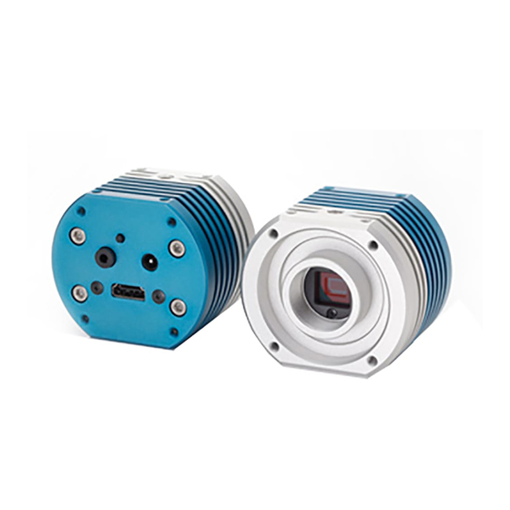
No. 17S142-00 Mechanical Specifications Product STC-HD853HDMI Dimensions Φ 70 x 60 (H) x 50.7 (D) mm (*1) Optical Filter IR cut filter with OPLF Material Aluminum (AC) Lens Mount C mount (*2) Interface Connector Video Output: HDMI connector, Power Input: Φ 2.5 mm power jack External Control: Φ... -
Page 12: Dimensions
15.5 Screw for camera tripod depth 6.0 (One on top, one on bototm) 4-M4 depth 5.0 (Four on top, four on bottom) φ 70 4-M4 depth 5.0 4-M4 depth 5.0 50.5 Unit: mm STC-HD853HDMI 12/81 Product specifications and User’s guide... -
Page 13: Camera Instruction Guide
White Balance can be set through push button. (*1) Single Push: Push to set White Balance Hold: Auto White Balance Push button position (*1) This push button can be assigned another function through control software STC-HD853HDMI 13/81 Product specifications and User’s guide... -
Page 14: External Switch (Remote Controller)
The default function assigns for SW-A to SW-F as follow functions. SW-A: Display OSD Menu SW-B: Up Cursor (Menu and Select Setting) SW-C: Left Cursor (Select Setting) SW-D: Execute SW-E: Right Cursor (Select Setting) SW-F: Down Cursor (Menu and Select Setting) STC-HD853HDMI 14/81 Product specifications and User’s guide... -
Page 15: Menu On Screen With External Switch
Default: AUTO a) AUTO The AGC for ALC operation. which is gain adjust automatically based on brightness of image. b) FIXED The fixed gain for ALC operation. The fixed gain controls by “GAIN” manually. STC-HD853HDMI 15/81 Product specifications and User’s guide... - Page 16 It is necessary to set the manual gamma setting with control software through PC. Setting selection: MANUAL / 0.30 / 0.45 / 0.50 / 0.60 / 0.70 / 0.80 / 0.90 / 1.00 Default: MANUAL (optimal gamma setting) STC-HD853HDMI 16/81 Product specifications and User’s guide...
- Page 17 Setting range: 0 to 1,023 Default: 256 4) B GAIN Sets the manual B gain for manual white balance. This is valid when “MANUAL” is selecting at “WB MODE”. Setting range: 0 to 1,023 STC-HD853HDMI 17/81 Product specifications and User’s guide...
- Page 18 The SN ratio deteriorates for other than edge parts is prevented by cutting signal level that smaller than this setting. (The image becomes soft image if this setting sets too large.) Setting range: 0 to 63 Default: 03 STC-HD853HDMI 18/81 Product specifications and User’s guide...
- Page 19 Four horizontal and four vertical line makers can be display. This setting is linked “LINE” setting on PAGE 4. Selection: ON / OFF Default: ON a) ON The line makers can be display. b) OFF Line Markers do NOT display. STC-HD853HDMI 19/81 Product specifications and User’s guide...
- Page 20 Setting selection: BLACK / WHITE / RED / GREEN / BLUE / CYAN / MAGENTA / YELLOW / USER0 / USER1 / USER2 / USER3 / USER4 / USER5 / USER6 / USER7 Default: BLACK STC-HD853HDMI 20/81 Product specifications and User’s guide...
- Page 21 Four horizontal and four vertical line makers can be display. This setting is linked “LINE” setting on PAGE 3. Selection: ON / OFF Default: ON a) ON The line makers can be display. b) OFF Line Markers do NOT display. STC-HD853HDMI 21/81 Product specifications and User’s guide...
- Page 22 Setting selection: BLACK / WHITE / RED / GREEN / BLUE / CYAN / MAGENTA / YELLOW / USER0 / USER1 / USER2 / USER3 / USER4 / USER5 / USER6 / USER7 Default: BLACK STC-HD853HDMI 22/81 Product specifications and User’s guide...
- Page 23 No. 17S142-00 The example of display lines LINE2 V POS LINE1 V POS Vertical line 1 Vertical line 2 LINE1 H POS Horizontal line 1 LINE2 H POS Horizontal line 2 STC-HD853HDMI 23/81 Product specifications and User’s guide...
- Page 24 To change the PRESET, select PRESET and use SAVE function after change the settings. Setting selection: PRESET0 / PRESET1 / PRESET2 / PRESET3 / PRESET4 / PRESET5 / PRESET6 / PRESET7 Default: PRESET0 STC-HD853HDMI 24/81 Product specifications and User’s guide...
- Page 25 Default: STANDARD a) STANDARD The normal image (no-flip). b) INVERSION The horizontal flip image. c) V INVERSION The vertical flip image. d) HV INVERSION The horizontal and vertical flip (180 deg. rotate) image. STC-HD853HDMI 25/81 Product specifications and User’s guide...
- Page 26 It is necessary to power off / on camera to apply factory default settings to camera. The setting save is abort when selecting other than “Execute” button while “ARE YOU OK?” message is displaying. Note: When executing “RESET”, all preset number of PRESET go back to factory default. STC-HD853HDMI 26/81 Product specifications and User’s guide...
-
Page 27: Control Software User's Guide
After installing KPACtrl, control software can be launched from KPACtrl.exe. Selects the COM port number through “Port Setting” under “Comm(C)” in menu. Selects “Read All” button to read all settings from camera. All camera settings can be configurable through control software. STC-HD853HDMI 27/81 Product specifications and User’s guide... -
Page 28: Button Descriptions
Mainly video control functions are in DSP register area. The communication settings and other functions such as button settings are in uCOM register. DSP has eight User Presets and user can configure each DSP Preset for each application. STC-HD853HDMI 28/81 Product specifications and User’s guide... -
Page 29: Functional Description
4) ACL rapid control frame number Sets number of frames for ALC rapid control when power on camera or change “Resolution / Framer rate”. ALC control speed (ALC integration-frame number) is disregard within this frames. STC-HD853HDMI 29/81 Product specifications and User’s guide... - Page 30 “AEE tolerance + AEE threshold”. 8) AEE speed Sets the maximum amount of exposure time change for AEE control. (There is no limitation for maximum amount of exposure time when setting “0”) STC-HD853HDMI 30/81 Product specifications and User’s guide...
- Page 31 AGC control starts when difference between “current brightness of image” and “ALC target level” becomes greater than “AGC tolerance + AGC threshold”. 8) AGC speed Sets the maximum amount of gain change for AGC control. (There is no limitation for maximum amount of gain when setting “0”) STC-HD853HDMI 31/81 Product specifications and User’s guide...
- Page 32 “Average photometry” or “Weight photometry” is selectable for Photometry mode. The brightness of image adjusts automatically by weighting for nine frames on image. a) Average photometry Equal weighting for all nine frames b) Weight photometry Sets weighting for each frame STC-HD853HDMI 32/81 Product specifications and User’s guide...
- Page 33 8) AWB rapid control frame number Sets number of frames for AWB rapid control when power on camera or change “Resolution / Framer rate”. AWB processing speed (AWB integration-frame number) is disregard within this frames. STC-HD853HDMI 33/81 Product specifications and User’s guide...
- Page 34 No. 17S142-00 AWB (Limited gain) STC-HD853HDMI 34/81 Product specifications and User’s guide...
- Page 35 Pull-in AWB processing starts when AWB tolerance becomes greater than “AWB tolerance (Pull-in limit)” + AWB threshold (Pull-in limit)”. 9) AWB step division (Pull-in limit) Sets step division for AWB for Pull-in AWB operation. STC-HD853HDMI 35/81 Product specifications and User’s guide...
- Page 36 Sets the maximum amount of R and B gain change for none pull-in AWB processing. (This is valid when selecting “Disable” at Pull-in limit in auto white balance mode) (There is no limitation for maximum amount of gain when setting “0”) STC-HD853HDMI 36/81 Product specifications and User’s guide...
- Page 37 Sets the manual gamma control point 0 to point 9 with checking below gamma curve. 2) Preset gamma Selects gamma from “Through, 0.3, 0.45, 0.5, 0.6, 0.7, 0.8, 0.9 and 1.0” when selecting “Preset” at Gamma mode. STC-HD853HDMI 37/81 Product specifications and User’s guide...
- Page 38 No. 17S142-00 Manual Gamma 1) Manual Gamma Control Points Sets the manual gamma control point 0 to point 9 with checking gamma curve. STC-HD853HDMI 38/81 Product specifications and User’s guide...
- Page 39 High luminance chroma suppress 1) High luminance chroma suppress The false color may appear on high luminance part of image. Adjust “High luminance chroma suppress threshold” and “High luminance chroma suppress slope” to eliminate false color. STC-HD853HDMI 39/81 Product specifications and User’s guide...
- Page 40 3) Aperture coring When using aperture processing, noise level is also enhanced. The signal level smaller than this value will be cut then prevent deterioration of SN ratio at flat part (excluding edge) of image. STC-HD853HDMI 40/81 Product specifications and User’s guide...
- Page 41 Enabled the line maker displays. Sets the color and thickness of horizontal and vertical lines. When the thickness of line is “0”, line maker does not display. Adjusts display position of line maker with “Line maker position”. STC-HD853HDMI 41/81 Product specifications and User’s guide...
- Page 42 2) Horizontal line maker position (Line Maker 1 to 4) Sets display position for individual horizontal line. 3) Horizontal line maker thickness (Line Maker 1 to 4) Sets thickness for individual horizontal line. STC-HD853HDMI 42/81 Product specifications and User’s guide...
- Page 43 Selects color for individual vertical line. 5) Vertical line position (Line Maker 1 to 4) Sets display position for individual vertical line. 6) Vertical line thickness (Line Maker 1 to 4) Sets thickness for individual vertical line. STC-HD853HDMI 43/81 Product specifications and User’s guide...
- Page 44 The vertical flipped image is out. 4) Color / Black and white “Color” or “Black and white” is selectable. a) Color The color image is out. b) Black and white The monochrome image is out. STC-HD853HDMI 44/81 Product specifications and User’s guide...
- Page 45 2) OSD control switch Selects switch for below functions while display menu. a) Menu page increment b) Menu down c) Menu up d) Menu right e) Menu left Menu turn off g) Menu enter STC-HD853HDMI 45/81 Product specifications and User’s guide...
- Page 46 No. 17S142-00 3) External switch Please use 3.5φStereo Pin Jack for external switch. Switch Circuit Diagram 1.8K 3.3K 4.7K SW-A SW-B SW-C SW-D SW-E SW-F Switch Example SW-A SW-B SW-D SW-C SW-E SW-F STC-HD853HDMI 46/81 Product specifications and User’s guide...
- Page 47 The controllable range for position can be adjusting individually. 2) Controllable range for line maker thickness by push button The line maker thickness can be change between “Min. thickness” and “Max. thickness”. The controllable range for thickness can be adjusting individually. STC-HD853HDMI 47/81 Product specifications and User’s guide...
- Page 48 V Line Maker 3 Position (-) H Line Maker 4 Position (+) H Line Maker 4 Position (-) V Line Maker 4 Position (+) V Line Maker 4 Position (-) UserPreset (+) UserPreset Reset STC-HD853HDMI 48/81 Product specifications and User’s guide...
- Page 49 The user color can be assign for line maker color, is adjustable. These settings are common settings for all DSP preset. User Defined Color 1) User defined color (1 to 7) Adjust Red, Green and Blue component for each user defined color. STC-HD853HDMI 49/81 Product specifications and User’s guide...
- Page 50 The display starts position for OSD menu adjusts manually. Adjust “OSD horizontal position” and “OSD vertical position”. 4) OSD RGB level Sets brightness level of character for OSD menu. 5) OSD Edge level Sets edge level of character for OSD menu. STC-HD853HDMI 50/81 Product specifications and User’s guide...
- Page 51 Other 1) HDMI out range “Limited” or “Full” is selectable for HDM output range. 2) Test pattern selection “OFF” (image out), “Gray Scale”, “Color Bar” or “Color Bar + Gray Scale” is selectable. STC-HD853HDMI 51/81 Product specifications and User’s guide...
- Page 52 No. 17S142-00 uCOM: ReadOnly The firmware version and FPGA version of camera can be check. Version Information STC-HD853HDMI 52/81 Product specifications and User’s guide...
- Page 53 Pixel blemish correction 1) Pixel blemish correcting function “Enable” or “Disable” is selectable. a) Enable The defect pixel is corrected image is out. b) Disable The original image that is not correcting defective pixel. STC-HD853HDMI 53/81 Product specifications and User’s guide...
- Page 54 7) Short Blemish Pixel The position for defective pixel has to order of raster scan (upper left on image to lower right on image). The position for defective pixels are sorting as raster scan order. STC-HD853HDMI 54/81 Product specifications and User’s guide...
- Page 55 No. 17S142-00 OSD Cmd The OSD functionality can be check. STC-HD853HDMI 55/81 Product specifications and User’s guide...
- Page 56 No. 17S142-00 Field: Table The parameters can be check on the list. When selecting left click on “Register” value on each parameter, parameter can be change on this list. STC-HD853HDMI 56/81 Product specifications and User’s guide...
-
Page 57: The Communication Protocol Specifications
“Check sum” function is verifying the integrity of communication transmission. “Check sum” value should equal last (low) eight bits of summary of [“Command” + “Function” + “Data length” + “Data”]. End Of Frame. This value is always “0x03”. STC-HD853HDMI 57/81 Product specifications and User’s guide... -
Page 58: Camera Control Commands
[END_L] + [DATA (START)] + [DATA (START + 1)] + … + [DATA (END)]” e.g. Sending command read data from 0000 to 03FF addresses of IC (Slave address: 21[h]) (02, 4A, 00, 05, 21, 00, 00, 03, FF, 72, 03) STC-HD853HDMI 58/81 Product specifications and User’s guide... - Page 59 Please refer “OSCD (On Screen Character Display) command” for more details. e.g. Sending command to display “0123” on third low of first column. (02, 50, 80, 0A 08, 92, 18, 38, DC, 10, 11, 12, 13, FF, E5, 03) STC-HD853HDMI 59/81 Product specifications and User’s guide...
-
Page 60: Slave Address For The Ics (8 Bits) List
02, FF, 00, 02, 10, 00, 11, 03 Note.1: The camera disregards data, which is not start with SOF. Note.2: The time out error is occurred when does not receive next data three seconds after receive data. STC-HD853HDMI 60/81 Product specifications and User’s guide... -
Page 61: Ucom Register Mapping List
1: Receiving data from camera is excluding data of write command and data length is 0. Check sum for UART communication 0: Disabled 1: Enabled * When selecting “Disabled”, camera processes sending command even check sum does not correct. STC-HD853HDMI 61/81 Product specifications and User’s guide... - Page 62 * Selection is same as Address 028h function Control button assigns to “Return” when displaying OSD * Selection is same as Address 028h function Control button assigns to “Execute” when displaying OSD * Selection is same as Address 028h function STC-HD853HDMI 62/81 Product specifications and User’s guide...
- Page 63 Minimum vertical position for line make while controlling by push button Maximum vertical position for line make while controlling by push button 2,160 Maximum vertical size for line make while controlling by push button 2,160 046 – 04F Reserved STC-HD853HDMI 63/81 Product specifications and User’s guide...
- Page 64 1: Gray scale 2: Color bar 3: Color bar + Gary scale Reserved 058 – 2FF Reserved Firmware version [little – endian] (Read Only) FPGA version [little – endian] (Read Only) 304 – 3FF Reserved STC-HD853HDMI 64/81 Product specifications and User’s guide...
- Page 65 Horizontal position of defective pixel 005 Vertical position of defective pixel 005 Horizontal position of defective pixel 006 Vertical position of defective pixel 006 Horizontal position of defective pixel 007 Vertical position of defective pixel 007 STC-HD853HDMI 65/81 Product specifications and User’s guide...
- Page 66 Position of defective pixel 448 to 463 D40 – Position of defective pixel 464 to 479 D80 – Position of defective pixel 480 to 495 DC0 – Position of defective pixel 496 to 511 STC-HD853HDMI 66/81 Product specifications and User’s guide...
-
Page 67: Push Button Function For Osd
Moves vertical line maker 4 to left direction 0x20 User preset (+) Changes user preset (0 to 1 to … to 7 to 0 to …) 0x21 Rest user preset Reset user preset (change user preset to “Preset 0”) STC-HD853HDMI 67/81 Product specifications and User’s guide... -
Page 68: Dsp Register Mapping List
“AEE control tolerance + AEE control threshold”. AEE control speed Sets the maximum amount of exposure time change for AEE control. (There is no limitation for maximum amount of exposure time when sets “0”) Reserved STC-HD853HDMI 68/81 Product specifications and User’s guide... - Page 69 01B – Reserved The formula for gain: Gain [dB] = - 20 x log ((2,048 – PGC) / 2,048) PGC = Gain setting x 5 (When Gain setting is 392, PGC = 1,957) STC-HD853HDMI 69/81 Product specifications and User’s guide...
- Page 70 The maximum exposure time for AEE sets at [0x00A - 0x00B]. The minimum gain for AGC sets at [0x012 - 0x013]. The middle gain for AGC sets at [0x014 - 0x015]. The maximum gain for AGC sets at [0x016 - 0x017]. STC-HD853HDMI 70/81 Product specifications and User’s guide...
- Page 71 4: 8 frames 5: 16 frames 6: 32 frames 7: 64 frames 8: 128 frames 9: 256 frames 10: 512 frames R change limit for none pull-in AWB B change limit for none pull-in AWB STC-HD853HDMI 71/81 Product specifications and User’s guide...
- Page 72 “R gain + frame” for high color temperature direction “R gain - frame” for high color temperature direction “B gain + frame” for high color temperature direction “B gain - frame” for high color temperature direction 050 – Reserved STC-HD853HDMI 72/81 Product specifications and User’s guide...
- Page 73 * Please sets with complement on two. Manual gamma control point 8 [little-endian] * Please sets with complement on two. Manual gamma control point 9 [little-endian] * Please sets with complement on two. 078 – 07F Reserved STC-HD853HDMI 73/81 Product specifications and User’s guide...
- Page 74 5 frame coefficient (valid when selecting weight photometry) 6 frame coefficient (valid when selecting weight photometry) 7 frame coefficient (valid when selecting weight photometry) 8 frame coefficient (valid when selecting weight photometry) 08A – 0FF Reserved STC-HD853HDMI 74/81 Product specifications and User’s guide...
- Page 75 Horizontal Line Maker 3 thickness [little-endian] 0: No display 2,160: Maximum thickness Vertical Line Maker 3 position [little-endian] 0: Left 3,840: Right Vertical Line Maker 3 thickness [little-endian] 0: No display 3,840: Maximum thickness Reserved STC-HD853HDMI 75/81 Product specifications and User’s guide...
- Page 76 Yellow User Defined Color 0 User Defined Color 1 User Defined Color 2 User Defined Color 3 User Defined Color 4 User Defined Color 5 User Defined Color 6 User Defined Color 7 STC-HD853HDMI 76/81 Product specifications and User’s guide...
- Page 77 * Please sets with complement on two. Range: -128 to 127 High luminance chroma suppress threshold Range: 0 to 255 High luminance chroma suppress slope Range: 0 to 8 Aperture horizontal gain Aperture vertical gain Aperture coring 146– Reserved STC-HD853HDMI 77/81 Product specifications and User’s guide...
-
Page 78: Oscd (On Screen Character Display) Command
(000: x1, 001: x2, 010: x3, 011: x4, 100: x5, 101: x6, 110: x7, 111: x8) SH1, SH0: Size on Horizontal (00:0 x1, 001: x2, 010: x3, 011: x4, 100: x5, 101: x6, 110: x7, 111: x8) AR3, AR2, AR1, AR0: RAW (0 to 11) STC-HD853HDMI 78/81 Product specifications and User’s guide... -
Page 79: Bytes Consecutive Command
Character C7 - C0 Character C7 - C0 Character “ < > & ‘ > fill ¥ < fill △ ▽ ・ ・・ ・・・ ~ ◆ × ÷ Finish 2 Bytes consecutive Command STC-HD853HDMI 79/81 Product specifications and User’s guide... -
Page 80: Revisions
No. 17S142-00 Revisions Date Changes Note 2018/08/08 New document Note. All specifications are subject to change without prior notice. STC-HD853HDMI 80/81 Product specifications and User’s guide... - Page 81 No. 17S142-00 9F, Ebina Prime Tower 9-50, Chuo 2 chome Ebina-city, Kanagawa 243-0432 Japan TEL 81-46-236-6660 FAX 81-46-236-6661 URL http://www.sentech.co.jp/ STC-HD853HDMI 81/81 Product specifications and User’s guide...
Need help?
Do you have a question about the STC-HD853HDMI and is the answer not in the manual?
Questions and answers