Table of Contents
Advertisement
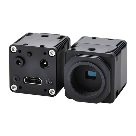
16:9 Format 1080p
STC-HD213 Series Color CMOS Camera
STC-HD213DV
STC-HD213DV-CS
STC-HD213SDI
STC-HD213SDI-CS
STC-HD213DVN
STC-HD213DVN-CS
STC-HD213SDIN
STC-HD213SDIN-CS
Product Specifications and User's Guide
STC-HD213DV / STC-HD213DV-CS / STC-HD213SDI / STC-HD213SDI-CS /
STC-HD213DVN / STC-HD213DVN-CS / STC-HD213SDIN / STC-HD213SDIN-CS
Product Specifications and User's Guide
(DVI output / C mount)
(DVI output / CS mount)
(SDI output / C mount)
(SDI output / CS mount)
(Non-Memory / DVI output / C mount)
(Non-Memory / DVI output / CS mount)
(Non-Memory / SDI output / C mount)
(Non-Memory / SDI output / CS mount)
No. 20S071-01
1/94
Advertisement
Table of Contents

Related Manuals for Omron STC-HD213 Series


Summary of Contents for Omron STC-HD213 Series
- Page 1 No. 20S071-01 16:9 Format 1080p STC-HD213 Series Color CMOS Camera STC-HD213DV (DVI output / C mount) STC-HD213DV-CS (DVI output / CS mount) STC-HD213SDI (SDI output / C mount) STC-HD213SDI-CS (SDI output / CS mount) STC-HD213DVN (Non-Memory / DVI output / C mount)
-
Page 2: Table Of Contents
No. 20S071-01 Table of Contents Product Precautions .................... 6 Warranty ........................ 6 Introduction ......................7 Features ............................ 7 Product Number Naming Method ................... 7 Peripheral Equipment ......................8 Specifications ....................... 9 Electronic specifications ......................9 STC-HD213DV / STC-HD213DV-CS / STC-HD213DVN / STC-HD213DVN-CS ......... 9 STC-HD213SDI / STC-HD213SDI-CS / STC-HD213SDIN / STC-HD213SDIN-CS ...... - Page 3 No. 20S071-01 Camera Setting through External Switch (Remote Controller) .......... 20 Camera Setting through Switch that has 3.5φStereo Pin Jack ............ 20 Menu on screen with External Switch ................... 21 Control Software User’s Guide................34 System Requirements ......................34 Basic Operating Procedure ....................34 Button Description .........................
- Page 4 No. 20S071-01 Precautions for safe use Please read carefully this “Precautions for safe use” before use the camera. Then the camera uses correctly with agreeing with below notes. In this “Precautions for safe use”, notes divides into “Warning” and “Caution” to use the camera safety and prevent to harm and damage.
- Page 5 No. 20S071-01 Caution The camera housing is not connecting to 0 V line It is necessary to wiring and mounting that is of camera inside circuit. specified in the specifications for this camera. There is a risk of short circuit between camera This will cause of fire or malfunction.
-
Page 6: Product Precautions
No. 20S071-01 Product Precautions Do not give shock to the camera. Do not haul or damage the camera cable. Do not wrap the camera with any material while using the camera. This will cause the internal camera temperature to increase. -
Page 7: Introduction
No. 20S071-01 Introduction This document describes specification of following cameras: STC-HD213DV / STC-HD213DV-CS (DVI output model) STC-HD213SDI / STC-HD213SDI-CS (SDI output model) STC-HD213DVN / STC-HD213DVN-CS (Non-Memory DVI output model) STC-HD213SDIN / STC-HD213SDIN-CS (Non-Memory SDI output model) 3.1 Features 1080p / 1080i / 720p output ... -
Page 8: Peripheral Equipment
No. 20S071-01 Peripheral Equipment We supplying follow peripheral equipment as option. +12V DC Power Supply: UN310-1210 Remote Controller: RC-HD133 Communication Tool (communicate through USB port on PC): JIG-USB-HD Control Software: JTBCtrl (Free) Note: This camera may become hot when operating 1080p60, 59.94, 50, 1080i60, 59.94, 50 output. Please do not use camera without original camera housing. -
Page 9: Specifications
No. 20S071-01 Specifications Electronic specifications STC-HD213DV / STC-HD213DV-CS / STC-HD213DVN / STC-HD213DVN-CS Model Number STC-HD213DV / STC-HD213DV-CS STC-HD213DVN / STC-HD213DVN-CS Image Sensor 1/2.8" 2M Progressive Color CMOS (SONY: IMX291) Shutter Type Rolling Shutter HD Active Picture Elements 1,920 (H) x 1,080 (V) Cell Size 2.9 (H) x 2.9 (V) µm Sync. -
Page 10: Stc-Hd213Sdi / Stc-Hd213Sdi-Cs / Stc-Hd213Sdin / Stc-Hd213Sdin-Cs
No. 20S071-01 (*1) The longest exposure time is depending on video output mode. STC-HD213SDI / STC-HD213SDI-CS / STC-HD213SDIN / STC-HD213SDIN-CS Model Number STC-HD213SDI / STC-HD213SDI-CS STC-HD213SDIN / STC-HD213SDIN-CS Image Sensor 1/2.8" 2M Progressive Color CMOS (SONY: IMX291) Shutter Type Rolling Shutter HD Active Picture Elements 1,920 (H) x 1,080 (V) Cell Size... -
Page 11: Spectral Sensitivity Characteristics
No. 20S071-01 (*1) The longest exposure time is depending on video output mode Spectral Sensitivity Characteristics STC-HD213DV / STC-HD213DV-CS / STC-HD213SDI / STC-HD213SDI-CS / 11/94 STC-HD213DVN / STC-HD213DVN-CS / STC-HD213SDIN / STC-HD213SDIN-CS Product Specifications and User’s Guide... -
Page 12: Mechanical Specifications
No. 20S071-01 Mechanical Specifications STC-HD213DV / STC-HD213DV-CS / STC-HD213DVN / STC-HD213DVN-CS Model Number STC-HD213DV / STC-HD213DVN STC-HD213DV-CS / STC-HD213DVN-CS Dimensions 40 (W) x 40 (H) x 48.9 (D) mm (*1) 40 (W) x 40 (H) x 43.9 (D) mm (*1) Optical Filter IR cut filter with OPLF Optical Center Accuracy... -
Page 13: Environmental Specifications
No. 20S071-01 Environmental Specifications STC-HD213DV / STC-HD213DV-CS / STC-HD213SDI / STC-HD213SDI-CS Model Number STC-HD213DV / STC-HD213DV-CS STC-HD213SDI / STC-HD213SDI-CS Operational Temperature / Humidity Environmental Temperature: 0 to +40 deg. C, Environmental Temperature: 0 to +43 deg. C, Environmental Humidity: 0 to 85 %RH Environmental Humidity: 0 to 85 %RH (No condensation) (No condensation) -
Page 14: External Control Specification
No. 20S071-01 External Control Specification Circuit Diagram of SW Board to connect 3.5φStereo Pin Jack 1.8K 3.3K 4.7K SW-A SW-B SW-C SW-D SW-E SW-F STC-HD213DV / STC-HD213DV-CS / STC-HD213SDI / STC-HD213SDI-CS / 14/94 STC-HD213DVN / STC-HD213DVN-CS / STC-HD213SDIN / STC-HD213SDIN-CS Product Specifications and User’s Guide... -
Page 15: Dimensions
No. 20S071-01 Dimensions STC-HD213DV / STC-HD213DVN Tripod depth5 (Top and bottom) 12.5 33.1 4-M4 depth5 (Top and bottom) (Top and bottom are same design) (53.36) 48.9 1”-32UNF C mount unit: mm STC-HD213DV / STC-HD213DV-CS / STC-HD213SDI / STC-HD213SDI-CS / 15/94 STC-HD213DVN / STC-HD213DVN-CS / STC-HD213SDIN / STC-HD213SDIN-CS Product Specifications and User’s Guide... -
Page 16: Stc-Hd213Dv-Cs / Stc-Hd213Dvn-Cs
No. 20S071-01 STC-HD213DV-CS / STC-HD213DVN-CS 33.1 Tripod depth5 (Top and bottom) 4-M4 depth5 (Top and bottom) (Top and bottom are same design) (48.36) 43.9 1”-32UNF CS mount unit: mm STC-HD213DV / STC-HD213DV-CS / STC-HD213SDI / STC-HD213SDI-CS / 16/94 STC-HD213DVN / STC-HD213DVN-CS / STC-HD213SDIN / STC-HD213SDIN-CS Product Specifications and User’s Guide... -
Page 17: Stc-Hd213Sdi / Stc-Hd213Sdin
No. 20S071-01 STC-HD213SDI / STC-HD213SDIN Tripod depth5 (Top and bottom) 12.5 33.1 4-M4 depth5 (Top and bottom) (Top and bottom are same design) (61) 48.9 1”-32UNF C mount unit: mm STC-HD213DV / STC-HD213DV-CS / STC-HD213SDI / STC-HD213SDI-CS / 17/94 STC-HD213DVN / STC-HD213DVN-CS / STC-HD213SDIN / STC-HD213SDIN-CS Product Specifications and User’s Guide... -
Page 18: Stc-Hd213Sdi-Cs / Stc-Hd213Sdin-Cs
No. 20S071-01 STC-HD213SDI-CS / STC-HD213SDIN-CS 33.1 Tripod depth5 (Top and bottom) 4-M4 depth5 (Top and bottom) (Top and bottom are same design) (55.1) 43.9 1”-32UNF CS mount unit: mm STC-HD213DV / STC-HD213DV-CS / STC-HD213SDI / STC-HD213SDI-CS / 18/94 STC-HD213DVN / STC-HD213DVN-CS / STC-HD213SDIN / STC-HD213SDIN-CS Product Specifications and User’s Guide... -
Page 19: Camera Instruction Guide
No. 20S071-01 Camera instruction guide This camera can be set through three setting settings as follows. A. Push Button B. External Switch (Remote controller: RC-HD133) *option C. Through the control software *as for detail, please refer to another chapter Push Button White Balance can be set through push button. -
Page 20: Camera Setting Through External Switch (Remote Controller)
No. 20S071-01 Camera Setting through External Switch (Remote Controller) Remote controller (Model:RC-HD133) is option, remote controller is not included camera Camera Setting through Switch that has 3.5φStereo Pin Jack A. Please assign each function through control software in advance B. Connector The location of 3.5φStereo Pin Jack for each model C. -
Page 21: Menu On Screen With External Switch
No. 20S071-01 Menu on screen with External Switch Page 1 PAGE 1 2 3 4 5 6 LUMINANCE GAIN SHUTTER GAMMA MANUAL 1) ALC Selects enable / disable for auto exposing and auto gain (AGC) operation from below two selections. (Default: ON). - Page 22 No. 20S071-01 4) AEE Selects exposing operation from below two exposing operations. (Default: AUTO) The setting is valid when selecting “ON” at “ALC”. a) AUTO The brightness of image will be maintaining to keep target brightness of image (with LUMINANCE setting) with auto exposing function.
- Page 23 No. 20S071-01 Page 2 PAGE 1 2 3 4 5 6 WB MODE AUTO R GAIN B GAIN SHARPNESS H03 V03 CORING 1) WB MODE Selects the white balance mode from below two modes. (Default: AUTO). a) AUTO The auto white balance operation. b) MANUAL The manual white balance operation with adjustable “R GAIN”...
- Page 24 No. 20S071-01 Page 3 PAGE 1 2 3 4 5 6 GRAPHICS LINE LINE1 H POS 0000 SIZE 0000 COLOR BLACK V POS 0000 SIZE 0000 COLOR BLACK LINE2 H POS 0000 SIZE 0000 COLOR BLACK V POS 0000 SIZE 0000 COLOR BLACK 1) GRAPHICS Selects enable or disable for line makers, shadow mask and circle marker displaying.
- Page 25 No. 20S071-01 3) LINE1 (Horizontal line 1 maker and vertical line 1 maker settings) Sets the color, size (thickness) and position for horizontal line marker 1 and vertical line marker 1. a) H POS Sets the position for horizontal line marker 1. Setting range: 0 (Top) to 1,080 (Bottom) Default: 0 b) H SIZE...
- Page 26 No. 20S071-01 4) LINE2 (Horizontal line 2 maker and vertical line 2 maker settings) Sets the color, size (thickness) and position for horizontal line marker 2 and vertical line marker 2. a) H POS Sets the position for horizontal line marker 2. Setting range: 0 (Top) to 1,080 (Bottom) Default: 0 b) H SIZE...
- Page 27 No. 20S071-01 Page 4 PAGE 1 2 3 4 5 6 GRAPHICS SHADOW ON GRADE 000 H T 0000 B 1020 V L 0000 R 1280 CIRCLE RADIUS 000 SIZE 000 H POS 0960 V POS 0540 COLOR BLACK 1) GRAPHICS Selects enable or disable for line makers, shadow mask and circle marker displaying.
- Page 28 No. 20S071-01 2-2) SHADOW H T Sets the height of shadow mask from top of image. Setting range: 0 (Top) to 1,079 (Bottom) Default: 0 2-3) SHADOW H B Sets the height of shadow mask from bottom of image. Setting range: 0 (Top) to 1,080 (Bottom) Default: 0 2-4) SHADOW V L Sets the width of shadow mask from left of image.
- Page 29 No. 20S071-01 3) CIRCLE Selects enable or disable for circle maker display (Default: ON). This setting is valid when selecting “ON” at “GRAPHICS”. a) ON The circle maker is displaying. Sets the radius, line size (thickness), center position and color for circle maker. The circle marker does not display if size (thickness) of circle is “0”...
- Page 30 No. 20S071-01 RADIUS COLOR H POS, V POS SIZE STC-HD213DV / STC-HD213DV-CS / STC-HD213SDI / STC-HD213SDI-CS / 30/94 STC-HD213DVN / STC-HD213DVN-CS / STC-HD213SDIN / STC-HD213SDIN-CS Product Specifications and User’s Guide...
- Page 31 No. 20S071-01 Page 5 PAGE 1 2 3 4 5 6 RES / FPS AUTO OSD SIZE LARGE PROFILES PRESET0 PATTERNS IMAGE OUTPUT STANDARD OUTPUT RANGE FULL 1) RES / FPS Sets the video format and frame rate for video output from below twelve output formats for DVI output models, eleven output format for SDI output models.
- Page 32 No. 20S071-01 4) PATTERNS Selects the output signal (video and test pattern) from below four output signals. (Default: OFF (Vide output)) a) OFF The video is output from camera. b) GRAY The gray scale test pattern is output from camera. c) COLOR The color test pattern is output from camera.
- Page 33 No. 20S071-01 Page 6 PAGE 1 2 3 4 5 6 EEPROM SAVE 1) EEPROM The camera settings in page1 to page5 can be saving into camera as default settings. 1-1) SAVE When executing “SAVE”, confirmation message “ARE YOU OK?” is displayed. When executing again, the settings save into camera.
-
Page 34: Control Software User's Guide
No. 20S071-01 Control Software User’s Guide System Requirements +12V DC Power Supply: UN310-1210 Communication Tool (Communicate through USB port on PC): JIG-USB-HD Control Software: JTBCtrl Basic Operating Procedure Connects the power supply with camera, and connect Communication Tool with PC via USB cable after installing JTBCtrl, control software can be launched from JTACtrl.exe. -
Page 35: Button Description
No. 20S071-01 Button Description Read All Read out All of DPS register and uCOM register settings on camera. Please execute this button when turning on camera every time. DSP -> EEPROM Save the DSP register settings (that settings are on DSP tab) into EEPROM. uCOM ->... -
Page 36: Functional Description
No. 20S071-01 Functional Description DSP: Shutter/GainTab The settings for exposing and gain are changeable. These can be change individual DSP User Preset. 1) ALC mode Selects enable or disable for ALC mode. When selecting “Enable”, please set “Exposure time control”, “Gain control” and below control settings for ALC mode. - Page 37 No. 20S071-01 Exposure time control 1) Exposure time control Selects exposing control method from “Fixed exposure time” and “Auto exposing (AEE)”. 2) Exposure Time Sets the exposure time for fixed exposure time control. 3) AEE minimum exposure time, AEE middle exposure time and AEE maximum exposure time The exposure time for is changing automatically with these settings, based on brightness of object.
- Page 38 No. 20S071-01 Gain Control 1) Gain control Selects gain control method from “Fixed gain” and “Auto (AGC)”. 2) Gain value Sets the gain for fixed gain control. 3) AGC minimum gain, AGC middle gain and AGC maximum gain The gain for AGC is changing automatically with these settings, based on brightness of object. It is necessary to set minimum, middle and maximum AGC gain as below order.
- Page 39 No. 20S071-01 Weight Photometry 1) Photometry mode Selects photometry mode for ALC control from “Average photometry” and “Weight photometry”. When selecting “Average photometry” same weight is applying for all nine frames. When selecting “Weight photometry”, individual weight is applying for each frame. STC-HD213DV / STC-HD213DV-CS / STC-HD213SDI / STC-HD213SDI-CS / 39/94 STC-HD213DVN / STC-HD213DVN-CS / STC-HD213SDIN / STC-HD213SDIN-CS...
- Page 40 No. 20S071-01 DSP: WhiteBalance The settings for white balance are changeable. These can be change individual DSP User Preset. 1) White balance mode Selects the white balance mode from “Manual” and “Auto (AWB)” “Manual” mode is white balance process with manual white balance gain “White balance R gain” and “White balance B gain”.
- Page 41 No. 20S071-01 AWB (Limited gain) STC-HD213DV / STC-HD213DV-CS / STC-HD213SDI / STC-HD213SDI-CS / 41/94 STC-HD213DVN / STC-HD213DVN-CS / STC-HD213SDIN / STC-HD213SDIN-CS Product Specifications and User’s Guide...
- Page 42 No. 20S071-01 1) R gain and B gain reference level of low color temperature Sets the R and B gain reference level for low color temperature of AWB control. 2) R gain and B gain reference level of middle color temperature Sets the R and B gain reference level for middle color temperature of AWB control.
- Page 43 No. 20S071-01 DSP: Gamma The settings for gamma are changeable. These can be change individual DSP User Preset. Gamma 1) Gamma mode Selects the gamma mode from “Preset” and “Manual”. When selecting “Preset” gamma mode, gamma control with selected preset gamma at “Preset gamma” is valid. When selecting “Manual”...
- Page 44 No. 20S071-01 Manual Gamma 1) Gamma control point 0 to 9 It is necessary to adjust gamma control point with displaying “Gamma Curve”. These settings are valid when selecting “Manual” at “Gamma mode”. STC-HD213DV / STC-HD213DV-CS / STC-HD213SDI / STC-HD213SDI-CS / 44/94 STC-HD213DVN / STC-HD213DVN-CS / STC-HD213SDIN / STC-HD213SDIN-CS Product Specifications and User’s Guide...
- Page 45 No. 20S071-01 DSP: Other The settings for “Resolution and frame rate”, flip image and “Color / Monochrome” are changeable. These can be change individual DSP User Preset. DSP Other 1) Resolution/FrameRate Selects the video output format from “1080p 60fps”, “1080p 59.94fps”, “1080p 50fps”, “1080p 30fps”, “1080p 29.97fps”, “1080i 60fps”, “1080i 59.94fps”, “1080i 50fps”, “720p 60fps”, “720p 59.94fps”...
- Page 46 No. 20S071-01 DSP: Chroma The settings for color (gain / saturation, and hue) are changeable. These can be change individual DSP User Preset. 1) R-Y Gain and B-Y Gain Sets gain (saturation) of color with “R-Y Gain” and “B-Y Gain”. 2) R-Y Hue and B-Y Hue Sets hue of color with “R-Y Hue”...
- Page 47 No. 20S071-01 DSP: Aperture The settings for aperture (edge enhancement) are changeable. These can be change individual DSP User Preset. Aperture 1) Aperture H Gain Sets horizontal aperture gain. When setting great value, horizontal edge enhancement becomes strong. 2) Aperture V Gain Sets vertical aperture gain.
- Page 48 No. 20S071-01 DSP: Marker The settings for markers (line markers, shadow mask and circle marker) are changeable. These can be change individual DSP User Preset. Marker 1) Marker Selects enable or disable for displaying markers. When selecting “Enable”, line markers, shadow mask and circle marker are displaying. It is necessary to set color, thickness (size) and displaying position for each marker and shadow mask.
- Page 49 No. 20S071-01 Line Marker 1) Line marker Selects enable or disable for displaying line markers. When selecting “Enable”, line markers are displaying. It is necessary to set color, thickness (size) and displaying position for each line marker. When selecting “Disable”, any line markers do not display. 2) Horizontal line 1 maker color and Horizontal line 2 marker color Selects color for horizontal line individually.
- Page 50 No. 20S071-01 6) Vertical line 1 maker position and Vertical line 2 marker position Sets displaying position (pixels) for vertical line individually. When setting small value, vertical line is displaying at right part of image. When setting great value, vertical line is displaying at left part of image. 7) Vertical line 1 thickness and Vertical line 2 marker thickness Sets thickness (size) for vertical line individually.
- Page 51 No. 20S071-01 Circle Marker 1) Circle marker Selects enable or disable for displaying circle marker. When selecting “Enable”, circle marker is displaying. It is necessary to set color, radius, thickness and displaying position for circle marker. When selecting “Disable”, circle marker does not display. 2) Circle marker color Selects color for circle marker.
- Page 52 No. 20S071-01 DSP: Pseudo The settings for Pseudo mode (color, threshold and slope) are changeable. These can be change individual DSP User Preset. Pseudo 1) Picture mode selection Selects picture mode from “Normal” and “Pseudo”. When selecting “Normal”, original image is output from camera. When selecting “Pseudo”, pseudo image is output from camera.
- Page 53 No. 20S071-01 6) Pseudo color slope Sets slope for banalization of pseudo image. STC-HD213DV / STC-HD213DV-CS / STC-HD213SDI / STC-HD213SDI-CS / 53/94 STC-HD213DVN / STC-HD213DVN-CS / STC-HD213SDIN / STC-HD213SDIN-CS Product Specifications and User’s Guide...
- Page 54 No. 20S071-01 uCOM: UserColor The settings for user defined color of makers are changeable. These are applying all DSP User Presets. Pseudo 1) User defined color 0 to 7 Sets R, G and B elements for user defined color individually. STC-HD213DV / STC-HD213DV-CS / STC-HD213SDI / STC-HD213SDI-CS / 54/94 STC-HD213DVN / STC-HD213DVN-CS / STC-HD213SDIN / STC-HD213SDIN-CS...
- Page 55 No. 20S071-01 uCOM: Push Button The settings for push buttons are changeable. These are applying all DSP User Presets. Push Button 1) Push button activation Selects enable or disable for push button on camera and external switch functionality. When selecting “Enable”, push button on camera and external switch functionality are activate and assigned function can be using.
- Page 56 No. 20S071-01 9) External switch Switch Circuit Diagram, 1.8K 3.3K 4.7K SW-A SW-B SW-C SW-D SW-E SW-F Example SW-A SW-B SW-D SW-C SW-E SW-F STC-HD213DV / STC-HD213DV-CS / STC-HD213SDI / STC-HD213SDI-CS / 56/94 STC-HD213DVN / STC-HD213DVN-CS / STC-HD213SDIN / STC-HD213SDIN-CS Product Specifications and User’s Guide...
- Page 57 No. 20S071-01 Line Maker (position/thickness) 1) Horizontal line Min. and Max. position (for push button) Sets the minimum and maximum position of horizontal line that can be controlling with push button function. 2) Horizontal line Max. thickness (for push button) Sets the maximum thickness of horizontal line that can be controlling with push button function.
- Page 58 No. 20S071-01 Direct Key Function 1) Switch function (single push / hold) Selects the function for “single push” and “hold” action at individual button including push button on camera and buttons on external switch, from below selection. Disabled Display menu Push Lock WB [Save] WB Mode (Auto) [Save] Change H inversion...
- Page 59 No. 20S071-01 uCOM: Other The settings for User Preset, OSD, Digital Zoom, test pattern display, output range for DVI output and still image are changeable. * Digital Zoom and still image functions are only available for STC-HD213DV, HD213DV-CS, HD213SDI and HD213SDI-CS * Output range for DVI output is only available for DVI output models.
- Page 60 No. 20S071-01 Digital Zoom 1) Digital zoom Sets the magnification for digital zooming. 2) Digital zoom pan Sets pan (horizontal offset) for digital zooming image. 3) Digital zoom tilt Sets tilt (vertical offset) for digital zooming image. Other 1) Test pattern selection Selects the test parttan to check connecting monitor form “OFF (Video out)”, “Gray scale”, “Color bar”...
- Page 61 No. 20S071-01 uCOM: UART The settings for UART communication are changeable. UART 1) UART baud rate Selects baud rate for UART communication from “9600bps”, “19200bps”, “38400bps”, “57600bps” and “115200bps”. 2) UART short reply for write When selecting “OFF”, receiving data from camera for writing command, does not include written data. When selecting “ON”, receiving data from camera for writing command, includes written data.
- Page 62 No. 20S071-01 uCOM: Blemish Pixel The defective pixel detection and correction can be process. The maximum 256 defective pixels can be correcting. Pixel blemish correction 1) Pixel blemish correcting function When selecting “OFF”, original video without defective pixel correction is output form camera. When selecting “ON”, defective pixel corrected video is output from camera.
- Page 63 No. 20S071-01 4) Auto white blemish detection threshold Sets brightness threshold to detect defective pixel (white pixel / hot pixel) at detection process. 5) Auto black blemish detection threshold Sets brightness threshold to detect defective pixel (dark pixel) at detection process. 6) Blemish pixel 000 to 255 horizontal and vertical position Sets X and Y coordinates of defective pixel.
- Page 64 No. 20S071-01 uCOM: ReadOnly The version of firmware and FPGA of camera are displaying. Version Information OSD Cmd The OSD functionality can be check. STC-HD213DV / STC-HD213DV-CS / STC-HD213SDI / STC-HD213SDI-CS / 64/94 STC-HD213DVN / STC-HD213DVN-CS / STC-HD213SDIN / STC-HD213SDIN-CS Product Specifications and User’s Guide...
- Page 65 No. 20S071-01 Field Table The settings of camera including on EEPROM can be check on this table. When selecting “Register” on each setting by left-click, each setting can be change on this table. Define the eight color table. The defined color can be used as Pseudo color and Line marker.. STC-HD213DV / STC-HD213DV-CS / STC-HD213SDI / STC-HD213SDI-CS / 65/94 STC-HD213DVN / STC-HD213DVN-CS / STC-HD213SDIN / STC-HD213SDIN-CS...
-
Page 66: The Communication Protocol Specifications
No. 20S071-01 The Communication Protocol Specifications The communication settings Setting Value Baud rate 9,600 bps / 19,200 bps / 38,400 bps (Default) / 57,600 bps / 115,200 bps Data bit 8 bits Parity None Stop bit 1 bit Flow control None The communication format The format for sending / receiving data between PC and camera is in below:... -
Page 67: Camera Control Commands
No. 20S071-01 Camera control commands All data in this section is described in Hexadecimal format (HEX). The command list for communication Command Details (HEX) The format for reading data to camera IC’s is as follows: In the case of writing, since maximum number of addresses can be written at once is 32 addresses, data must be written 8 times separately if 256 bytes data must be written. - Page 68 No. 20S071-01 Command Details (HEX) The format for writing data to camera IC’s is as follows: Send Data 02, 4A, [DataLenH] + 80, [DataLenL], [SLV], [START_H], [START_L], [END_H], [END_L], [DATASTART], [DATASTART + 1], … , [DATAEND], [CHK], 03 [CHK] = Lower 8bits of “4A + ([DataLenH] +80) + [DataLenL] + [SLV] + [START_H] + [START_L] + [END_H] + [END_L] + [DATASTART] + [DATASTART + 1] + …...
-
Page 69: Slave Address For Ics (8Bits) List
No. 20S071-01 Slave address for ICs (8bits) list Slave Address 詳細 DSP data EEPROM The Virtual EEPROM zone for currently selected DSP preset mode of Preset 0 to Preset 7 EEPROM The EEPROM zone for Preset 0 DSP data EEPROM The EEPROM zone for Preset 1 DSP data EEPROM The EEPROM zone for Preset 2 DSP data... -
Page 70: The Ucom Register Mapping List
No. 20S071-01 The uCOM register mapping list * Please do not change “Reserved data”. Address Descriptions Default User Preset DSP register setting can save on eight Preset areas. * When this vale saves to EEPRM, camera starts with saved DSP mode at power up. - Page 71 No. 20S071-01 Address Descriptions Default User defined color 0 Red User defined color 0 Green User defined color 0 Blue User defined color 1 Red User defined color 1 Green User defined color 1 Blue User defined color 2 Red User defined color 2 Green User defined color 2 Blue User defined color 3 Red...
- Page 72 No. 20S071-01 Address Descriptions Default Default function of primary switch WB: single push * As for the detail of selectable function, please refer to Push button function list Default function of external switch A: single push * As for the detail of selectable function, please refer to Push button function list Default function of external switch B: single push * As for the detail of selectable function, please refer to Push...
- Page 73 No. 20S071-01 Address Descriptions Default Vertical line minimum position [little-endian] (to Push Button) Vertical line maximum position [little-endian] (to Push Button) 1,080 Vertical line minimum size (thickness) [little-endian] 1,080 (to Push Button) Shadow Horizontal minimum position [little-endian] (for Push Button) Shadow Horizontal maximum position [little-endian] 1,920 (for Push Button)
- Page 74 No. 20S071-01 Address Descriptions Default Reserved Digital zoom pan (Horizontal Offset) [little-endian] Two's complement * This setting is valid only STC-HD213DV, HD213DV-CS, HD213SDI and HD213SDI-CS. Reserved Digital zoom tilt (Vertical Offset) [little-endian] Two's complement * This setting is valid only STC-HD213DV, HD213DV-CS, HD213SDI and HD213SDI-CS.
- Page 75 No. 20S071-01 Address Descriptions Default Threshold of detecting hot defective pixel (White pixel) When detecting defective pixel, pixel has greater pixel value than this setting, is detecting as hot defective pixel. Threshold of detecting dead defective pixel (Black pixel) When detecting defective pixel, pixel has smaller pixel value than this setting, is detecting as hot defective pixel.
- Page 76 No. 20S071-01 Address Descriptions Default 6C0 - Defective pixel position 048 to 063 700 - Defective pixel position 064 to 079 740 - Defective pixel position 080 to 095 780 - Defective pixel position 096 to 111 7C0 - Defective pixel position 112 to 0127 800 - Defective pixel position 128 to 143 840 -...
-
Page 77: Push Button Function On Meru
No. 20S071-01 Push Button Function on Meru When menu is displayed, the following function is assign for each Push Button. WB: Increment Page increment page number SW A: Return Close the menu SW B: Increment Cursor moves to up / increment value SW C: Select Left Select left selection SW D: Execute... -
Page 78: Push Button Function List
No. 20S071-01 Push button function list Value Function Function Descriptions 0x00 Disabled Disables push button control 0x01 Display Menu Displaying the menu on screen 0x02 Push Lock WB [Save to EEPROM] Execute Push to set white balance process then save mode and gain settings to EEPROM 0x03 WB mode (AWB) [Save to EEPROM]... - Page 79 No. 20S071-01 Value Function Function Descriptions 0x29 User Preset 0 Loads settings of user preset 0 0x2A User Preset 1 Loads settings of user preset 1 0x2B User Preset 2 Loads settings of user preset 2 0x2C User Preset 3 Loads settings of user preset 3 0x2D User Preset 4...
-
Page 80: The Dsp Register Mapping List
No. 20S071-01 The DSP register mapping list * Please do not change access “Reserved data”. Address Descriptions Default ALC mode 0: Disable (fixed exposing / fixed gain) 1: Enable (exposing control / gain control) Reserved Exposing control (AEE) 0: Fixed exposing 1: Auto exposing (AEE) Gain control 0: Fixed gain... - Page 81 No. 20S071-01 Address Descriptions Default AEE maximum exposure time [little-endian] * Two’s compliment -447 to 561 * 0 to 561 for STC-HD213DVN, HD213DNV-CS, HD213SDIN and HD213SDIN-CS Brightness tolerance for AEE control The auto exposing control is stopped when differences between “target brightness”...
- Page 82 No. 20S071-01 30 fps frame rate Setting Exposure time Setting Exposure time 33.27 [msec.] 1/30.1 [sec.] 66.7 [msec.] 1/15 [sec.] 19.97 [msec.] 1/50.1 [sec.] -128 133.3 [msec.] 2/15 [sec.] 16.65 [msec.] 1/60.1 [sec.] -192 266.7 [msec.] 4/15 [sec.] 8.36 [msec.] 1/119.7 [sec.] -256 533.3 [msec.]...
- Page 83 No. 20S071-01 Address Descriptions Default Gain Range: 0 to 150 Minimum gain for AGC Range: 0 to 150 Middle gain for AGC Range: 0 to 150 Maximum gain for AGC Range: 0 to 150 Brightness tolerance for AGC control The AGC control is stopped when differences between “target brightness”...
- Page 84 No. 20S071-01 Address Descriptions Default White balance mode 0: Manual 1: Auto (AWB) Gain limit for AWB 0: Disable (no pull-in limit) 1: Enable (with pull-in limit) Reserved White balance gain data saves to EEPROM when finishing push to set white balance process 0: OFF (data does not save) 1: ON (data saves and automatically turn 0) Push to set white balance mode...
- Page 85 No. 20S071-01 Address Descriptions Default Auto white balance (no pull-in limit) process speed (AWB R) Auto white balance (no pull-in limit) process speed (AWB B) R gain for low color temperature reference point [little-endian] B gain for low color temperature reference point [little-endian] R gain for middle color temperature reference point [little-endian] B gain for middle color temperature reference point [little-endian] R gain for high color temperature reference point [little-endian]...
- Page 86 No. 20S071-01 Address Descriptions Default Resolution/Frame Rate 0: 1080p 60fps 1: 1080p 30fps 2: 1080i 60fps 3: 1080p 50fps 4: 1080pP 25fps 5: 1080i 50fps 6: 720p 60fps 7: 720p 50 fps 8: 1080p 59.94fps 9: 1080p 29.97fps 10: 1080i 59.94fps 11: 720p 59.94fps 12: Auto * Auto is only available for DVI output models.
- Page 87 No. 20S071-01 Address Descriptions Default Manual Gamma 7 [little-endian] * Two’s compliment Manual Gamma 8 [little-endian] * Two’s compliment Manual Gamma 9 [little-endian] * Two’s compliment 078 - Reserved Photometry Mode In order to achieve the optimum luminance, photometry mode of this DSP either automatically adjusts gain value and exposure time to achieve optimum luminance level by detecting luminance signals in screen region using 9 frames (3 horizontal x 3 vertical frames) and giving weighting to this region on screen。...
- Page 88 No. 20S071-01 Address Descriptions Default Line Marker 0: Disable 1: Enabler Shadow Mask 0: Disable 1: Enable Circle Mask 0: Disable 1: Enable Reserved Marker 0: Disable 1: Enable Shadow mask shading level 0: Invisible to 255: Black Horizontal shadow mask top position [little-endian] 0: Top to 1,080: Bottom Horizontal shadow mask bottom position [little-endian] 1,080...
- Page 89 No. 20S071-01 Address Descriptions Default Circle marker color *as for the configurable color, please refer to color code chart Reserved Reserved Circle marker radius Circle marker thickness (size) Circle marker center position (horizontal) [little-endian] 0: Left to 1,920: Right Circle marker center position (vertical) [little-endian] 0: Top to 1,080: Bottom Picture mode selection 0: Normal...
- Page 90 No. 20S071-01 Color Code Table 16 defined colors can be selected from following table and these colors can be referring to Line Marker. As for User Defined Color 0 to 7, user can configure these colors setting through serial communication. Code Color Black...
-
Page 91: Oscd (On Screen Character Display) Command
No. 20S071-01 OSCD (On Screen Character Display) Command 2 Byte Command Note: The data have to send as follow order D15-D8, D7-D0. Function Video RAM Batch Clear Command Display Control Command Character Size Control Command Write Address Control Command Character Size Control Command Video RAM Batch Clear Command Clear the all character data (12Lines 28digits) on Video RAM. -
Page 92: Byte Consecutive Command
No. 20S071-01 2 Byte consecutive Command Note: The data have to send as follow order D15-D8, D7-D0. Function Display Character Control Command Display Character Control Command Sets the writing character data, character color, blink data into Video RAM address. This command is 2 Byte consecutive command, if more than 2 consecutive character writing are required, just send only lower 8bits (C7 to C0). -
Page 93: Revisions History
No. 20S071-01 Revisions History Date Changes Note 2020/07/20 New Document 2020/09/09 Revised Conformed WEEE Note: Product specifications would be changed without notification. Company names and product names in this document are trademarks of their respective owners. STC-HD213DV / STC-HD213DV-CS / STC-HD213SDI / STC-HD213SDI-CS / 93/94 STC-HD213DVN / STC-HD213DVN-CS / STC-HD213SDIN / STC-HD213SDIN-CS Product Specifications and User’s Guide... - Page 94 No. 20S071-01 19F, Ebina Prime Tower 9-50, Chuo 2 chome Ebina-city, Kanagawa 243-0432 Japan TEL 81-46-236-6660 FAX 81-46-236-6661 URL http://www.sentech.co.jp/ STC-HD213DV / STC-HD213DV-CS / STC-HD213SDI / STC-HD213SDI-CS / 94/94 STC-HD213DVN / STC-HD213DVN-CS / STC-HD213SDIN / STC-HD213SDIN-CS Product Specifications and User’s Guide...
Need help?
Do you have a question about the STC-HD213 Series and is the answer not in the manual?
Questions and answers