Table of Contents
Advertisement
GigE Vision
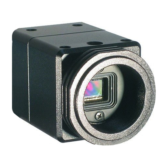
Color / Monochrome CMOS PoE Camera
STC-CMB2MPOE
STC-CMC2MPOE
STC-CMB2MPOE-IR (2M
STC-CMB4MPOE
STC-CMC4MPOE
STC-CMB4MPOE-IR (4M
Product Specifications and User's Guide
STC-CMC2MPOE / STC-CMB2MPOE / STC-CMB2MPOE-IR /
STC-CMC4MPOE / STC-CMB4MPOE / STC-CMB4MPOE-IR Product Specifications and User's Guide
Monochrome
(2M /
Color
(2M /
)
/ Near IR
Monochrome
(4M /
Color
(4M /
)
/ Near IR
)
)
)
)
No.13S064-13
1/55
Advertisement
Table of Contents

Related Manuals for Omron GigE Vision STC-CMB2MPOE


Summary of Contents for Omron GigE Vision STC-CMB2MPOE
- Page 1 No.13S064-13 GigE Vision Color / Monochrome CMOS PoE Camera Monochrome STC-CMB2MPOE (2M / Color STC-CMC2MPOE (2M / / Near IR STC-CMB2MPOE-IR (2M Monochrome STC-CMB4MPOE (4M / Color STC-CMC4MPOE (4M / / Near IR STC-CMB4MPOE-IR (4M Product Specifications and User’s Guide STC-CMC2MPOE / STC-CMB2MPOE / STC-CMB2MPOE-IR / 1/55 STC-CMC4MPOE / STC-CMB4MPOE / STC-CMB4MPOE-IR Product Specifications and User’s Guide...
-
Page 2: Table Of Contents
No.13S064-13 Table of Contents Product Precautions .................... 7 Warranty ........................ 7 Introduction ......................8 Features ............................ 8 Product Number Naming Method ................... 8 Specifications ....................... 9 Electronic Specifications ......................9 STC-CMB2MPOE / STC-CMC2MPOE ....................9 STC-CMB4MPOE / STC-CMC4MPOE ..................... 10 STC-CMB2MPOE-IR / STC-CMB4MPOE-IR .................. - Page 3 No.13S064-13 Camera Operational Modes ................25 Normal Mode ........................... 25 Pulse width trigger mode....................... 25 Timing .............................. 25 Exposure Timing with the Positive Polarity Trigger Signal ............26 Exposure Timing with the Negative Polarity Trigger Signal ............26 Edge Preset Trigger Mode ..................... 27 Timing ..............................
- Page 4 No.13S064-13 Saving the Camera Settings ......................42 Loading Camera Settings ....................... 43 Loading Camera Settings when the Camera Power is on ............43 Camera Settings Initialization ......................43 9.10 Trigger ..........................44 Trigger Signal Processing Process .................... 44 9.11 The camera settings (GenICam parameters) control with SDK ........45 Integer type parameter control ....................
- Page 5 No.13S064-13 Precautions for safe use Please read carefully this “Precautions for safe use” before use the camera. Then the camera uses correctly with agreeing with below notes. In this “Precautions for safe use”, notes divides into “Warning” and “Caution” to use the camera safety and prevent to harm and damage.
- Page 6 No.13S064-13 Caution The camera housing is not connecting to 0 V It is necessary to wiring and mounting that is line of camera inside circuit. specified in the specifications for this camera. There is a risk of short circuit between camera This will cause of fire or malfunction.
-
Page 7: Product Precautions
No.13S064-13 Product Precautions Do not give shock to the camera. Do not haul or damage the camera cable. Do not wrap the camera with any material while using the camera. This will cause the internal camera temperature to increase. ... -
Page 8: Introduction
No.13S064-13 Introduction This document describes the specification of the following cameras: STC-CMB2MPOE / STC-CMC2MPOE / STC-CMB2MPOE-IR STC-CMB4MPOE / STC-CMC4MPOE / STC-CMB4MPOE-IR Features Support PoE (Power over Ethernet Support) Maximum Frame Rate (Full Scanning): 50 fps @ 2M 8bits, 25 fps @ 4M 8bits ... -
Page 9: Specifications
No.13S064-13 Specifications Electronic Specifications STC-CMB2MPOE / STC-CMC2MPOE Model Number STC-CMB2MPOE STC-CMC2MPOE Image Sensor 2/3" 2M Progressive Monochrome CMOS 2/3" 2M Progressive Color CMOS (CMOSIS: CMV2000) (CMOSIS: CMV2000) Shutter Type Global Shutter Active Picture Elements 2,048 (H) x 1,088 (V) Cell Size 5.5 (H) x 5.5 (V) µm Sync Method External trigger (Hardware / Software) / Free run... -
Page 10: Stc-Cmb4Mpoe / Stc-Cmc4Mpoe
No.13S064-13 STC-CMB4MPOE / STC-CMC4MPOE Model Number STC-CMB4MPOE STC-CMC4MPOE Image Sensor 1" 4M Progressive Monochrome CMOS 1" 4M Progressive Color CMOS (CMOSIS: CMV2000) (CMOSIS: CMV4000) Shutter Type Global Shutter Active Picture Elements 2,048 (H) x 2,048 (V) Cell Size 5.5 (H) x 5.5 (V) µm Sync Method External trigger (Hardware / Software) / Free run Maximum... -
Page 11: Stc-Cmb2Mpoe-Ir / Stc-Cmb4Mpoe-Ir
No.13S064-13 STC-CMB2MPOE-IR / STC-CMB4MPOE-IR Model Number STC-CMB2MPOE-IR STC-CMB4MPOE-IR Image Sensor 2/3" 2M Progressive Near IR CMOS 1" 4M Progressive Near IR CMOS (CMOSIS: CMV2000) (CMOSIS: CMV4000) Shutter Type Global Shutter Active Picture Elements 2,048 (H) x 1,088 (V) 2,048 (H) x 2,048 (V) Cell Size 5.5 (H) x 5.5 (V) µm Sync Method... -
Page 12: Spectral Sensitivity Characteristics
No.13S064-13 Spectral Sensitivity Characteristics STC-CMB2MPOE / STC-CMB4MPOE STC-CMC2MPOE / STC-CMC4MPOE STC-CMC2MPOE / STC-CMB2MPOE / STC-CMB2MPOE-IR / 12/55 STC-CMC4MPOE / STC-CMB4MPOE / STC-CMB4MPOE-IR Product Specifications and User’s Guide... -
Page 13: Stc-Cmb2Mpoe-Ir / Stc-Cmb4Mpoe-Ir (Near Ir Model)
No.13S064-13 STC-CMB2MPOE-IR / STC-CMB4MPOE-IR (Near IR Model) Near IR Model Normal Model(Mono) STC-CMC2MPOE / STC-CMB2MPOE / STC-CMB2MPOE-IR / 13/55 STC-CMC4MPOE / STC-CMB4MPOE / STC-CMB4MPOE-IR Product Specifications and User’s Guide... -
Page 14: Mechanical Specifications
No.13S064-13 Mechanical Specifications Model Number STC-CMB2MPOE / STC-CMB4MPOE / STC-CMC2MPOE / STC-CMC4MPOE STC-CMB2MPOE-IR / STC-CMB4MPOE-IR Dimensions 35 (W) x 35 (H) x 55.9 (D) mm (*1) Optical Filter No Optical Filter No Optical Filter (*2) Optical Center Accuracy Positional accuracy in Horizontal and Vertical directions: +/- 0.3 mm Rotational accuracy of Horizontal and Vertical: +/- 2.0 deg. -
Page 15: Connector Specifications
No.13S064-13 Connector Specifications Power-I/O Connector RJ45 Connector RJ45 Connector This product is PoE compliant. Please supply power (+10.8 to +26.4 Vdc) through the power-I/O connector when using non-PoE-compliant NIC. Pin Assignment Pin No. Signal Name Green LED Yellow LED Status Green Light ON Yellow Light ON Power ON(1GB NIC) -
Page 16: Power And Control Signal Connector
No.13S064-13 Power and Control Signal Connector HR10A-7R-6PB (Hirose) or equivalent This connector is for the power supply (12Vdc) and input /output signals. Use HR10A-7P-6S (Hirose) or equivalent for the cable side. Pin assignment IN / Voltage Pin No. Signal Name I/O-1 +3.3 V Open Collector I/O-2... - Page 17 No.13S064-13 1) FrameTriggerWait The user can check the camera condition (camera exposure and image output processing by the trigger signal with this FrameTriggerWait signal). This signal is LOW for the period from the trigger input signal to the image output. 2) UserOutput The status of the UserOutput signal can change with the “UserOutputValue”.
-
Page 18: Equivalent Circuit For The Input Pin Of The I/O Connector
No.13S064-13 Equivalent Circuit for the Input Pin of the I/O Connector STC-CMC2MPOE / STC-CMB2MPOE / STC-CMB2MPOE-IR / 18/55 STC-CMC4MPOE / STC-CMB4MPOE / STC-CMB4MPOE-IR Product Specifications and User’s Guide... -
Page 19: Typical Input Circuit
No.13S064-13 Typical Input Circuit STC-CMC2MPOE / STC-CMB2MPOE / STC-CMB2MPOE-IR / 19/55 STC-CMC4MPOE / STC-CMB4MPOE / STC-CMB4MPOE-IR Product Specifications and User’s Guide... -
Page 20: Typical Output Circuit
No.13S064-13 Typical Output Circuit Note: Value of Vcc and Pull up register can be set within the spec of transistor. STC-CMC2MPOE / STC-CMB2MPOE / STC-CMB2MPOE-IR / 20/55 STC-CMC4MPOE / STC-CMB4MPOE / STC-CMB4MPOE-IR Product Specifications and User’s Guide... -
Page 21: Input And Output Signal Timing (Hardware Trigger)
No.13S064-13 Input and Output Signal Timing (Hardware Trigger) Case of “External Hardware Trigger”, “Positive Edge Trigger”, “Edge Preset Exposure”, Camera internal processing External hardware trigger Up to 15us Photocoupler output For the signal duration, refer to another chapter "Exposure". Filtering TriggerDelay on GenICam Trigger delay For the signal duration, refer to another chapter "Exposure". -
Page 22: Input And Output Signal Timing (Software Trigger)
No.13S064-13 Input and Output Signal Timing (Software Trigger) Case of “Software Trigger”, “Positive Edge Trigger”, “Edge Preset Exposure”, Camera internal processing Software trigger,PLC and Command TriggerDelay on GenICam Trigger delay For the signal duration, refer to another chapter "Exposure". Exposure ExposureTimeRaw on GenICam Video output Output Signal... -
Page 23: Dimensions
No.13S064-13 Dimensions Unit:mm STC-CMC2MPOE / STC-CMB2MPOE / STC-CMB2MPOE-IR / 23/55 STC-CMC4MPOE / STC-CMB4MPOE / STC-CMB4MPOE-IR Product Specifications and User’s Guide... -
Page 24: Sensor Information
No.13S064-13 Sensor information Pixel Transferring Image STC-CMB2MPOE / STC-CMC4MPOE (Monochrome) STC-CMB2MPOE-IR / STC-CMB4MPOE-IR (Near IR) Pixel1 of Pixel2 of Data Data Pixel (n) of Data: nth pixel being transferred STC-CMC2MPOE / STC-CMC4MPOE (Color) Pixel11 of Pixel12 of Data Data Pixe21 of Pixel22 of Data Data... -
Page 25: Camera Operational Modes
No.13S064-13 Camera Operational Modes Normal Mode E x p o s u r e T i m e S e n s o r E x p o s u r e I m a g e o u t Pulse width trigger mode In this trigger mode with positive polarity, the camera exposure starts at the rising edge of the trigger pulse and stops at the falling edge of the trigger pulse. -
Page 26: Exposure Timing With The Positive Polarity Trigger Signal
No.13S064-13 Exposure Timing with the Positive Polarity Trigger Signal Input Trigger signal Trigger signal (With Photocoupler delay Filtering *Note.1 Less than 15 useconds 30 CLK 75 CLK Exposure time Exposure time:: T1' = T1 + 127 CLK Note 1: The trigger signal will be removed by the filtering if the pulse width of the input trigger signal is less than 30 CLK. Please input a trigger signal with more than 31 CLK pulse width. -
Page 27: Edge Preset Trigger Mode
No.13S064-13 Edge Preset Trigger Mode In this “edge preset trigger mode”, the camera exposure starts at the rising edge of the trigger signal like the “pulse width trigger mode” in the previous sections. However, in this mode, the exposure duration time is based on the preset value stored by the by the camera setting communication. -
Page 28: Exposure Timing With The Positive Polarity Trigger Signal
No.13S064-13 Exposure Timing with the Positive Polarity Trigger Signal Input Trigger signal Trigger signal (With Photocoupler delay Filtering *Note.1 30 CLK Less than 15useconds 75 CLK Exposure time Exposure tim: T1' = Preset exposure time Note 1: The trigger signal will be removed by the filtering if the pulse width of the input trigger signal is less than 30 CLK. Please input a trigger signal with more than 31 CLK pulse width. -
Page 29: Edge Preset Trigger Mode (Trigger Input While The Image Is Out)
No.13S064-13 Edge Preset Trigger Mode (Trigger Input While the Image Is Out) In this trigger mode, the camera exposure starts at the rising edge of the trigger pulse. If trigger signal input is required while the image is out, then it is necessary to disable the trigger signal mask with the communication. -
Page 30: Camera Functions
No.13S064-13 Camera Functions ROI (Region of Interest) The specified area of the image can output from the camera with ROI function. The frame rate is increased when the height is reduced. The frame rate does not increase when the width is reduced. ROI (1 region) GenICamparamters Width... - Page 31 No.13S064-13 Width / Height setting range STC-CMB2MPOE STC-CMB4MPOE STC-CMC2MPOE STC-CMC4MPOE STC-CMB2MPOE-IR STC-CMB4MPOE-IR Width Range 8 to 2,048 pixels 8 to 2,048 pixels Default 2,048 2,048 Adjustment steps 8 pixels 8 pixels Height Range 4 to 1,088 lines 4 to 2,048 lines Default 1,088 lines 2,048 lines...
-
Page 32: Pixel Format
No.13S064-13 Pixel Format The image format from camera can be set on the Pixel Format. GenICam Parameters PixelFormat IEnumeration Type Pixel Format The following chart shows the available Pixel Formats on the camera: Output Bit Pixel Format Monochrome Camera Color Camera 8bits Mono8 BayerRG8... -
Page 33: Gain
No.13S064-13 Gain The analog gain and the digital gain are available for the gain control. Digital gain This parametersets the digital gain. GenICam parameter DigitalGain Integer type Digital gain. Range: 0 to 511, Default: 0 Digital gain formula Gain (xtimes) = 1+ (DigitalGain / 64) Black level This parameter sets the black level (the clamp level for the black signal). -
Page 34: Alc (Auto Light Control)
No.13S064-13 ALC (Auto Light Control) ALC function has two control methods, which is AGC (Auto Gain Control) and the auto shutter. The AGC and the auto shutter sets up individually. The camera parameters are adjusted to the brightness of the image is maintained with the target brightness automatically with the ALC function. -
Page 35: Alc Control Method
No.13S064-13 ALC control method The ALC control with the weight area1 to 9. The weight area setting parameters are in below: ALCWindowV1 Area1 Area2 Area3 ALCWindowV2 Area4 Area5 Area6 ALCWindowV3 Area7 Area8 Area9 ALCWindowV4 ALCWindowH4 ALCWindowH3 ALCWindowH2 ALCWindowH1 The brightness average and peak calculate for each weight area. The target brightness comparison value calculates with “ALC_Peak_Average”, the brightness average and peak then compare with the target brightness to define the necessary brightness control (to dark or to bright). -
Page 36: Auto Shutter
No.13S064-13 Auto shutter The brightness of the image maintains to the target brightness with the shutter automatically. If the brightness of the image is the darker than the target brightness, the exposure time extends up to Max_ShutterTime. If the brightness of the image is the brighter than the target brightness, the exposure time becomes shorter up to Min_ShutterTime. -
Page 37: White Balance (Only Available For The Color Cameras)
No.13S064-13 White balance (Only available for the color cameras) The color compensates with the gain adjustment each color. The gain for each color has to adjust with the flat white target to each color has the same brightness. The white balance control methods are the listed in the below: Auto white balance Push to set white balance Preset1 to 3... -
Page 38: Off
No.13S064-13 GenICam parameters BalanceRatio_R_Preset3 Integer type R white balance gain for preset3. Default: 0 BalanceRatio_Gr_Preset3 Integer type Gr white balance gain for preset3. Default: 0 BalanceRatio_B_Preset3 Integer type B white balance gain for preset3. Default: 0 BalanceRatio_Gb_Preset3 Integer type Gb white balance gain for preset3. Default: 0 The white balance with BalanceRatio_X_Once (X: R, Gr, B or Gb) If the white balance process is not necessary, please sets 0 for BalanceRatio_X_Once (X: R, Gr, B orGb) -
Page 39: Preset White Balance1 To 3
No.13S064-13 Preset white balance1 to 3 The camera has three preset manual white balance. Presets saving area Preset1: BalanceRatio_R_Preset1,BalanceRatio_Gr_Preset1, BalanceRatio_B_Preset1,BalanceRatio_Gb_Preset1 Preset2: BalanceRatio_R_Preset2,BalanceRatio_Gr_Preset2, BalanceRatio_B_Preset2,BalanceRatio_Gb_Preset2 Preset3: BalanceRatio_R_Preset3,BalanceRatio_Gr_Preset3, BalanceRatio_B_Preset3,BalanceRatio_Gb_Preset3 Preset white balance setting procedure 1. Sets the white balance gain for the preset1, 2 or 3. (X: 1 to 3) (BalanceRatio_R_PresetX, BalanceRatio_Gr_PresetX,BalanceRatio_B_PresetX,BalanceRatio_Gb_PresetX) 2. -
Page 40: White Balance Calculate Area Setting
No.13S064-13 White balance calculate area setting The white balance gain calculation area is changeable. GenICam parameters WB_WindowMode Enumeration White balance gain calculation area selection type Full screen (Off), Specified area (On). Default: Full screen WB_WindowV1 Integer type Vertical frame position for the specified area. WB_WindowV2 STC-CMC2MPOE STC-CMC4MPOE... -
Page 41: Gamma Correction
No.13S064-13 Gamma correction The gamma correction is the gamma = 1.0 or the gamma table control. GenICam parameters GammaMode Enumeration Gamma correction selection type Gamma = 1.0 (Off), Gamm table control (On). Default: Gamma = 1.0 ReloadGammaData Command type Gamma table loading from ROM to RAM Gamma table loading procedure (ReloadGammaData) 1. -
Page 42: Save And Load The Camera Setting Data
No.13S064-13 Save and load the camera setting data The camera has the camera setting including the factory default, load function. The camera has below two camera settings. Default: The factory default settings (This setting cannot change) User Set X: Over writeable camera settings (X: 0 to 7) These camera settings load from ROM to the register in the RAM on the camera and camera settings save to ROM. -
Page 43: Loading Camera Settings
No.13S064-13 Loading Camera Settings When UserSetLoad is executing, the camera settings load from the selected UserSetX ROM that was selected at “UserSetSelector” Camera to the register at RAM. Setting Default Selector UserSetSelector Setting Procedure 1. Select “UserSetX” (or Default) at “UserSetSelector” 2. -
Page 44: Trigger
No.13S064-13 9.10 Trigger The description of trigger type and characteristic, please refer to the chapter “Image acquisition and Camera Mode”. Trigger Signal Processing Process External Hardware Trigger or Software Trigger input the camera’s internal process as follows. Switching Trigger can be done through register access or GenICam commands Switching point 1: Switch to Hardware Trigger and Software Trigger TriggerSource = Software on GenICam TriggerSource = Hardware on GenICam... -
Page 45: The Camera Settings (Genicam Parameters) Control With Sdk
No.13S064-13 9.11 The camera settings (GenICam parameters) control with SDK GenICam parameters are controllable with the eBUS SDK. Please refer eBUS SDK API help file for the details. Integer type parameter control Integer type parameter such as “Width” control. e.g. Width writing [C++] PvDevice.GetGenParameters()->SetIntegerValue(“Width”, 256);... -
Page 46: String Type Paramter Control
No.13S064-13 String type paramter control String type parameter such as “DeviceModelName” control. e.g.DeviceModelName writing (DeviceModelName cannot overwrite) [C++] PvDevice.GetGenParameters()->SetString(“DeviceModelName”, “STC-SB33POE”); [C#] PvDevice.GenParameters.SetStringValue(“DeviceModelName”, “STC-SB33POE”); e.g. DeviceModelName reading [C++] PvDevice.GetGenParameters()->GetString(“DeviceModelName”, &PvStringValue); [C#] stringValue = PvDevice.GenParameters.GetStringValue(“DeviceModelName”); Boolean type parameter control Boolean type parameter such as “LineInverter0” control. e.g. -
Page 47: Genicam Command List
No.13S064-13 9.12 GenICam Command List DeviceControl Name Description DeviceVendorName Name of the manufacturer of the device. DeviceModelName Model of the device. DeviceManufacturerInfo Manufacturer information about the device. DeviceVersion Version of the device. DeviceID Device’s serial number. DeviceUserID User-programmable device identifier. DeviceScanType Scan type of the sensor of the device. -
Page 48: Acquisitioncontrol
No.13S064-13 AcquisitionControl Name Description AcquisitionMode Sets the acquisition mode of the device. It defines mainly the number of frames to capture during an acquisition and the way the acquisition stops. AcquisitionStart Starts the Acquisition of the device. The number of frames captured is specified by AcquisitionMode. -
Page 49: Counterandtimercontrol
No.13S064-13 CounterAndTimerControl Name Description CounterSelector Selects which Counter to configure. CounterEventSource Select the events that will be the source to increment the Counter. ConterDecrementEventSource Selects the event that decrements the counter. CounterResetSource Selects the signals that will be the source to reset the Counter. CounterResetActivation Selects the Activation mode of the Counter Reset Source signal. -
Page 50: Transportlayercontrol
No.13S064-13 TransportLayerControl Name Description PayloadSize Provides the number of bytes transferred for each image or chunk on the stream channel. GevVersionMajor Major version of the specification. GevVersionMinor Minor version of the specification. GevVDeviceModeIsBigEndian Endianess of the device registers. GevDeviceClass Returns the class of the device. GevDeviceModeCharacterSet Character set used by all strings of the bootstrap registers. -
Page 51: Usersetcontrol
No.13S064-13 Name Description GevMCTT Provides the transmission timeout value in miliseconds. GevMCRC Controls the number of retransmissions allowed when a message channel message time out. GevMCSP This feature indicates the source port for the message channel. GevStreamChanelSelector Selects the stream channel to control. GevSCPDirection Reports the direction of the stream channel. -
Page 52: Specialfeatures
No.13S064-13 SpecialFeatures Name Description SmearHalfReduction The upper half of smear is reduced when select “ON”. Set dauble frame rate mode. The number of the maximum horizontal pixels (width) is DoubleSpeedMode limited. DoubleSpeedModeTapsel Horizontal pixels region (tap) at DoubleSpeedMode. HDRSloop HDR mode can choose 2 sloope and 3 sloop mode. HDRKnee1 Set the ExposureTime for HDRKnee1 point. - Page 53 No.13S064-13 Name Description ALCWindowH1 horizontal (1 from the left) position for the area for ALC. ALCWindowH2 horizontal (2 from the left) position for the area for ALC. ALCWindowH3 horizontal (3 from the left) position for the area for ALC. ALCWindowH4 horizontal (4 from the left) position for the area for ALC.
-
Page 54: 10 Revision History
No.13S064-13 10 Revision History Date Changes Note 2013/10/21 New Document ・Combined Specification and User’s Guide 2013/10/31 Revised ・Added Technical Note 2013/11/19 Revised ・Added Pixel Blemish Correction 2013/12/27 Revised ・LED information on RJ45 2014/10/17 Revised ・Added TriggerOverlap on GenIcam 2015/01/15 Revised ... - Page 55 No.13S064-13 19F, Ebina Prime Tower 9-50, Chuo 2 chome Ebina-city, Kanagawa 243-0432 Japan TEL 81-46-236-6660 FAX 81-46-236-6661 URL http://www.sentech.co.jp/ STC-CMC2MPOE / STC-CMB2MPOE / STC-CMB2MPOE-IR / 55/55 STC-CMC4MPOE / STC-CMB4MPOE / STC-CMB4MPOE-IR Product Specifications and User’s Guide...
Need help?
Do you have a question about the GigE Vision STC-CMB2MPOE and is the answer not in the manual?
Questions and answers