Table of Contents
Advertisement
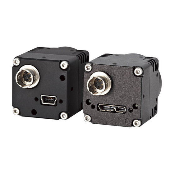
USB3 Vision
Monochrome / Color CMOS Camera
STC-MBS43U3V
STC-MCS43U3V
STC-MBS163U3V (1.6M / Monochrome)
STC-MCS163U3V (1.6M / Color)
Product Specifications and User's Guide
STC-MBS43U3V / STC-MCS43U3V / STC-MBS163U3V / STC-MCS163U3V
Product Specifications and Use's Guide
For more information please contact Aegis Electronic Group, Inc. *(888)687-6877 *aegis-g2@aegiselect.com *http://www.aegiselect.com
(0.4M / Monochrome)
(0.4M / Color)
No.17S010-01
1/68
Advertisement
Table of Contents

Related Manuals for Omron USB3 Vision Series


Summary of Contents for Omron USB3 Vision Series
- Page 1 No.17S010-01 USB3 Vision Monochrome / Color CMOS Camera STC-MBS43U3V (0.4M / Monochrome) STC-MCS43U3V (0.4M / Color) STC-MBS163U3V (1.6M / Monochrome) STC-MCS163U3V (1.6M / Color) Product Specifications and User’s Guide STC-MBS43U3V / STC-MCS43U3V / STC-MBS163U3V / STC-MCS163U3V 1/68 Product Specifications and Use’s Guide For more information please contact Aegis Electronic Group, Inc.
-
Page 2: Table Of Contents
No.17S010-01 Table of Contents Product Precautions .................... 9 Warranty ........................ 9 Overview ......................10 Features ............................. 10 Product Number Naming Method .................... 10 Specifications ...................... 11 Electronic Specifications ......................11 4.1.1 STC-MBS43U3V / STC-MCS43U3V ....................... 11 4.1.2 STC-MBS163U3V / STC-MCS163U3V ....................13 Spectral Sensitivity Characteristics .................. - Page 3 No.17S010-01 Image Acquisition and Camera Operational Modes (GenICam) ...... 29 Free run ............................29 Trigger Mode ..........................30 7.2.1 Frame Start Trigger (Edge Preset) ...................... 31 7.2.2 Frame Start Trigger (Pulse Width Trigger) ..................32 7.2.3 Exposure Start Trigger, Exposure End Trigger .................. 33 7.2.4 Trigger Software ..........................
- Page 4 No.17S010-01 Black Level..........................50 ALC (Auto Light Control) ......................50 9.9.1 ALC Control Method ..........................50 9.9.2 AGC (Auto Gain Control) ........................51 9.9.3 Auto Exposure ............................. 51 9.9.4 The setting procedure of ALC ......................51 9.10 White Balance (Only available for the color model) ............... 52 9.10.1 White balance control methods ......................
- Page 5 No.17S010-01 9.18.10 AnalogControl ..........................65 9.18.11 LUTControl ............................65 9.18.12 UserSetControl ..........................65 9.18.13 ChunkDataControl .......................... 66 9.18.14 TestControl ............................66 10 Revision History ....................67 STC-MBS43U3V / STC-MCS43U3V / STC-MBS163U3V / STC-MCS163U3V 5/68 Product Specifications and Use’s Guide For more information please contact Aegis Electronic Group, Inc. *(888)687-6877 *aegis-g2@aegiselect.com *http://www.aegiselect.com...
- Page 6 No.17S010-01 Precautions for safe use Please read carefully this “Precautions for safe use” before use the camera. Then the camera uses correctly with agreeing with below notes. In this “Precautions for safe use”, notes divides into “Warning” and “Caution” to use the camera safety and prevent to harm and damage.
- Page 7 No.17S010-01 Caution Do not grounding DC power (+) of all devices It is necessary to wiring and mounting that is that are connect to the camera. specified in the specifications for this camera. The camera housing is connecting to 0 V line of This will cause of fire or malfunction.
- Page 8 No.17S010-01 [Disposal] Caution It is necessary to dispose as industrial waste. STC-MBS43U3V / STC-MCS43U3V / STC-MBS163U3V / STC-MCS163U3V 8/68 Product Specifications and Use’s Guide For more information please contact Aegis Electronic Group, Inc. *(888)687-6877 *aegis-g2@aegiselect.com *http://www.aegiselect.com...
-
Page 9: Product Precautions
No.17S010-01 Product Precautions Do not give shock to the camera. Do not haul or damage the camera cable. Do not wrap the camera with any material while using the camera. This will cause the internal camera temperature to increase. ... -
Page 10: Overview
No.17S010-01 Overview This document describes the specification of the following cameras. STC-MBS43U3V / STC-MCS43U3V STC-MBS163U3V / STC-MCS163U3V Features ・USB3 Vision ・Maximum frame rate (Full resolution): 527.1 fps @ 0.4M 8bits, 238 fps @ 1.6M 8bits ・CMOS (Global Shutter) ・Up to 2,048 Pixel Defect Correction ・8bits, 10bits, 12bits output Product Number Naming Method STC-MxS43U3V... -
Page 11: Specifications
No.17S010-01 Specifications Electronic Specifications Model Number STC-MBS43U3V STC-MCS43U3V Image Sensor 1/2.9” 0.4M Progressive Monochrome CMOS 1/2.9” 0.4M Progressive Color CMOS (SONY: IMX287) (SONY: IMX287) Shutter Type Global Active Picture Elements 720 (H) x 540 (V) Cell Size 6.9 (H) x 6.9 (V) µm Sync System External trigger (Hardware, Software) / Free run Maximum... - Page 12 No.17S010-01 Model Number STC-MBS43U3V STC-MCS43U3V Image Flip Horizontal / Vertical / Horizontal and Vertical / Off Defective Pixel Correction Up to 2,048 points Auto Image Auto Exposure Support Support Control Auto Gain Support Support Auto White Balance Support Operational Mode Edge preset Trigger / Pulse width Trigger / Start Stop Trigger / Free run User Setting Storage Support...
-
Page 13: Stc-Mbs163U3V / Stc-Mcs163U3V
No.17S010-01 Model Number STC-MBS163U3V STC-MCS163U3V Image Sensor 1/2.9” 1.6M Progressive Monochrome CMOS 1/2.9” 1.6M Progressive Color CMOS (SONY: IMX273) (SONY: IMX273) Shutter Type Global Active Picture Elements 1,440 (H) x 1,080 (V) Cell Size 3.45 (H) x 3.45 (V) µm Sync System External trigger (Hardware, Software) / Free run Maximum... -
Page 14: Stc-Mbs163U3V
No.17S010-01 Model Number STC-MBS163U3V STC-MCS163U3V Auto Image Auto Exposure Support Support Control Auto Gain Support Support Auto White Balance Support Operational Mode Edge preset Trigger / Pulse width Trigger / Start Stop Trigger / Free run User Setting Storage Support Communication Through USB3.0 bus Interface... - Page 15 No.17S010-01 Precautions (*1) When selecting 8bits output, the priority mode (Image quality / Frame rate) can be selectable. When selecting “Image quality”, the maximum frame rate is reduced, but the low noise image is acquiring. When selecting “Frame rate”, the camera can be operated with the fastest frame rate of this camera, but noise level is greater than “Image quality”...
-
Page 16: Spectral Sensitivity Characteristics
No.17S010-01 4.2 Spectral Sensitivity Characteristics STC-MBS43U3V / STC-MCS43U3V / STC-MBS163U3V / STC-MCS163U3V 16/68 Product Specifications and Use’s Guide For more information please contact Aegis Electronic Group, Inc. *(888)687-6877 *aegis-g2@aegiselect.com *http://www.aegiselect.com... -
Page 17: Stc-Mcs163U3V (Without Ir Cut Filter)
No.17S010-01 STC-MBS43U3V / STC-MCS43U3V / STC-MBS163U3V / STC-MCS163U3V 17/68 Product Specifications and Use’s Guide For more information please contact Aegis Electronic Group, Inc. *(888)687-6877 *aegis-g2@aegiselect.com *http://www.aegiselect.com... -
Page 18: Ir Cut Filter (Stc-Mcs43U3V / Stc-Mcs163U3V)
No.17S010-01 STC-MBS43U3V / STC-MCS43U3V / STC-MBS163U3V / STC-MCS163U3V 18/68 Product Specifications and Use’s Guide For more information please contact Aegis Electronic Group, Inc. *(888)687-6877 *aegis-g2@aegiselect.com *http://www.aegiselect.com... -
Page 19: Mechanical Specifications
No.17S010-01 Mechanical Specifications Model Number STC-MBS43U3V STC-MCS43U3V Dimensions 28 (W) x 28 (H) x 40 (D) mm (*1) Optical Filter No Optical Cut Filter IR Cut Filter Optical Center Accuracy Positional accuracy in Horizontal and Vertical directions: +/- 0.3 mm Rotational accuracy of Horizontal and Vertical: +/- 1.5 deg. -
Page 20: Environmental Specifications
No.17S010-01 Environmental Specifications Model Number STC-MBS43U3V STC-MCS43U3V Operational Minimum Environmental Temperature: 0 deg. C, Temperature / Environmental Humidity: 0 to 85 %RH (No condensation) Humidity Maximum Camera housing temperature (top plate) shall not exceed 54 deg. C (*1), Storage Temperature / Humidity Environmental Temperature: -25 to +70 deg. -
Page 21: External Connector Specifications
No.17S010-01 External Connector Specifications IO Connector USB 3.0 micro B Connector This connector is compatible with a USB 3.0 micro B connector. Connector size includes screw lock size and complies with USB3 Vision 1.0.1. Pin assignment Pin No. Signal Name Description VBUS Power... - Page 22 No.17S010-01 HR10A-7R-6PB (Hirose) or equivalent. This connector is for input and output signals. Please use HR10A-7P-6S (Hirose) or equivalent connector for cable. Pin assignment Pin No. Signal Name IN/OUT GPIO_GND GPIO2 IN/OUT GPIO1 IN/OUT GPIO0 IN/OUT CAM_RESET N.C. * Possible Maximum Rated Voltage is +24 V on CAM_RESET, GPIO0, GPIO1 and GPIO2. * Please set “OPEN”...
-
Page 23: Reference Input Circuit
No.17S010-01 Default Setting of Input / Output Pin No. Signal Default Name IN/OUT Setting GPIO2 Disable GPIO1 Disable GPIO0 Disable CAM_RESET (Reference 1) The camera resets while “CAM_REST pin” connecting to GND 5 seconds in this circuit. The default camera setting is disable for this reset function. It is necessary to turn ON. General Purpose Input (Reference 2) STC-MBS43U3V / STC-MCS43U3V / STC-MBS163U3V / STC-MCS163U3V 23/68... - Page 24 No.17S010-01 Input Response Characteristics The response characteristics of CAM_RESET (Reference1), General Purpose Input (Reference 2) are shown in the following diagrams tIPDHL 0.13 µseconds tIPDLH 6.54 µseconds The capable input trigger’s pulse width is Positive Trigger: More than tIPDLH Negative Trigger: More than tIPDHL tIPDHL tIPDLH Internal Voltage (+3.3V)
-
Page 25: Reference Output Circuit
No.17S010-01 General Purpose Output (Reference 3) O General Purpose Output (Reference 4) STC-MBS43U3V / STC-MCS43U3V / STC-MBS163U3V / STC-MCS163U3V 25/68 Product Specifications and Use’s Guide For more information please contact Aegis Electronic Group, Inc. *(888)687-6877 *aegis-g2@aegiselect.com *http://www.aegiselect.com... - Page 26 No.17S010-01 Output Response Characteristics The response characteristics of the General Purpose output (Reference 3), and General Purpose output (Reference 4) are shown in the diagram below. Pulse width is configurable through software. Please refer to the following response timing table. VCCext OPEN (*1) 5 V (*2)
-
Page 27: Dimensions
No.17S010-01 Dimensions 12.5 2-M4 Depth4.0 3-M2 Depth2.3 (46.8) 6-M2 Depth2.3 (3-M2 on other side) 2-M2 Depth4.0 C mount 24.5 12.5 4-M4 Depth4.0 3-M2 Depth2.3 Unit: mm STC-MBS43U3V / STC-MCS43U3V / STC-MBS163U3V / STC-MCS163U3V 27/68 Product Specifications and Use’s Guide For more information please contact Aegis Electronic Group, Inc. *(888)687-6877 *aegis-g2@aegiselect.com *http://www.aegiselect.com... -
Page 28: Sensor Information
No.17S010-01 Sensor Information Pixel Transferring Image STC-MBS43U3V / STC-MBS163U3V (Monochrome) Pixel0 Pixel1 Data Data Pixel (n) of Data: nth pixel being transferred STC-MCS43U3V / STC-MCS163U3V (Color) Pixel00 Pixel01 Data Data Pixel10 Pixel11 Data Data Pixel (m, n) of Data: nth pixel of the mth line being transferred STC-MBS43U3V / STC-MCS43U3V / STC-MBS163U3V / STC-MCS163U3V 28/68 Product Specifications and Use’s Guide... -
Page 29: Image Acquisition And Camera Operational Modes (Genicam)
No.17S010-01 Image Acquisition and Camera Operational Modes (GenICam) Please refer to another chapter for the method of switching Trigger. GenICam Parameters TriggerSelector IEnumeration Type Select Trigger function TriggerMode IEnumeration Type Select ON / OFF which was selected function on TriggerSelector On: Trigger function ON, Off: Trigger function Off TriggerSource IEnumeration Type... -
Page 30: Trigger Mode
No.17S010-01 Trigger Mode This trigger consists of Frame Start, Exposure Start and Exposure End. 1) Frame Start This function has the capability to acquire an image from exposure through the trigger. The Frame Start function can be enabled when “Frame Start” is selected on Trigger Selector and the Trigger mode is set to “On”. -
Page 31: Frame Start Trigger (Edge Preset)
No.17S010-01 The exposure synchronizes trigger signal. The value on Exposure Time is actual exposure time. When the polarity on Line Inverter is positive (false), the Exposure starts on the rising edge of trigger. When the polarity on Line Inverter is negative (true), the Exposure starts on the falling edge of trigger. To work the camera under this mode, as following setting have to be set. -
Page 32: Frame Start Trigger (Pulse Width Trigger)
No.17S010-01 When operating in this mode, the exposure synchronizes the trigger signal. The exposure time can be controlled by the pulse width of Frame Start trigger. When the polarity on the Line Inverter is positive (false), the exposure can be controlled at a period of High level of input trigger signal. -
Page 33: Exposure Start Trigger, Exposure End Trigger
No.17S010-01 Exposure Start trigger determines exposure start timing, Exposure End trigger determines exposure end timing. To operate the camera under this mode, the following settings have to be set. ・Exposure Mode: Trigger Controlled ・Selects Trigger Selector: Exposure Start, and Trigger Mode: On ・Selects Trigger Selector: Exposure End, and Trigger Mode: On (*) On Trigger Mode except Frame Start should be set Off. -
Page 34: Io Function
No.17S010-01 IO Function This chapter describes the IO functions. In this chapter, the IO Port places as “Line”. The follow chart details the relationship of the Line and IO Port. Line number IO Port Signal Name Pin No. GPIO2 Line2 GPIO1 Line1 GPIO0... -
Page 35: Line Debouncer
No.17S010-01 Line Debouncer can reduce the wrong input signal detection that is noise on the signal or chartering, by the filtering input signal. GenICamParameters LineDebounceTime Integer Type Line Debounce Time Range: 0 to 10,000 μseconds, Default: 1 μseconds Timing Line入力信号 Line Input Line Debounce... -
Page 36: Output Port Function
No.17S010-01 Output Port Function This function sets the Output to Line Mode, and then the Line is assigned as the output. The following functions can be assigned when the IO port is used as the output signal port. The following list shows the configurable functions available through the Line Source. The function that describes as “Enable”... - Page 37 No.17S010-01 Line Source Timing トリガー入力 Trigger Input 露光 Exposure リードアウト ReadOut (Sensor to FPGA) (センサー to FPGA) VideoOut 映像出力 TriggerOutDelay Trigger Out出力 TriggerOutOnTime Trigger Out Output StrobeOutDelay 出力 StrobeOutOnTime Strobe Out Strobe Out Output 出力 Exposure Active Exposure Active Output TriggerOutDelay 出力...
-
Page 38: User Output
No.17S010-01 High or low level signal that was configured on the software is output. Setting Procedure Selects Line N (N: any number from 0, 1 or 2) 1) Sets the User Output N (N is Line number) as Line Source 2) Selects User Output N (N is same as selected Line number on User Output) on User Output Selector 3) Sets the value (True: High level, False: Low level) on User Output Value Monitor the status on output port. -
Page 39: Camera Functions
No.17S010-01 Camera Functions This chapter describes the camera functions. ROI (Region of Interest) This sets the ROI in order to output the selected area of image. The frame rate increases when reducing the height of image. The frame rate does not change when reducing the width of image. - Page 40 No.17S010-01 Width / Height setting range STC-MBS43U3V STC-MBS163U3V STC-MCS43U3V STC-MCS163U3V Width Setting range: 64 to 720 pixels 64 to 1,440 pixels (*) 704 pixels is maximum width on (*) 1,408 pixels is maximum width on Packed output Packed output Default: 720 pixels 1,440 pixels Setting steps...
-
Page 41: Multi Roi (Only Available For Stc-Mbs163U3V / Stc-Mcs163U3V)
No.17S010-01 When utilizing the Multi-ROI function, please make note of the following: This image format is Sentech original format, which does not comply with USB3Vision. Therefore, this Multi ROI will not work on 3 party applications that conform to USB3Vision. To use Multi ROI, one of following application is required. - Page 42 No.17S010-01 Restriction of ROI operation Region 0 is always ON Region(X+Y) can be enable (On) after sets ON Region (X) and Region (Y). The following restriction exist to set region’s Width, Height, OffsetX and OffsetY Width[Region0] = Width[Region1] Height[Region0] = Height[Region2] OffsetX[Region0] = OffsetX[Region1] OffsetY[Region0] = OffsetY[Region2] Overlapped region setting is invalid...
- Page 43 No.17S010-01 The region position when using image flip function Region, Width, Height, OffsetX and OffsetY at normal image is applying. Normal Region2 Region0 Region2 Region0 Region3 Region1 Region1 Region3 Horizontal flip Region1 Region1 Region3 Region3 Region2 Region0 Region2 Region0 Vertical flip Horizontal and vertical flip STC-MBS43U3V / STC-MCS43U3V / STC-MBS163U3V / STC-MCS163U3V 43/68...
-
Page 44: Pixel Format
No.17S010-01 Pixel Format The image format from camera can be set on the Pixel Format. GenICam Parameters PixelFormat IEnumeration Type Pixel Format The following chart shows the available Pixel Formats on the camera: Output Bit Pixel Format Monochrome Camera Color Camera 8bits Mono8 BayerRG8... -
Page 45: Decimation (Only Available For Stc-Mbs163U3V / Stc-Mcs163U3V)
No.17S010-01 Decimation (Only available for STC-MBS163U3V / STC-MCS163U3V) When using Decimation mode, the decimated image can be output. The images below show decimated pixels (red squares) where they are output. Decimation X(Off), Y(Off) Decimation X(Off), Y(On) Decimation X(On), Y(Off) Decimation X(On), Y(On) Decimation X(Off), Y(Off) Decimation X(Off), Y(On) Decimation X(On), Y(Off) -
Page 46: Image Flip
No.17S010-01 Image Flip Flip the image through ReverseX and ReverseY. GenICam Parameters ReverseX IBoolean Type Switch ON / OFF at Horizontal False: Horizontal Flip Off, True: Horizontal Flip On. Default: False ReverseY IBoolean Type Switch ON / OFF at Vertical False: Vertical Flip Off, True: Vertical Flip On. - Page 47 No.17S010-01 Reverse X(Off), Y(Off) Reverse X(Off), Y(On) Reverse X(On), Y(Off) Reverse X(On), Y(On) (*) When the image is flipping for color camera, the pixel array is also flipped. STC-MBS43U3V / STC-MCS43U3V / STC-MBS163U3V / STC-MCS163U3V 47/68 Product Specifications and Use’s Guide For more information please contact Aegis Electronic Group, Inc.
-
Page 48: Priority Mode
No.17S010-01 Priority Mode The frame rate prioritized mode or the Image quality prioritized mode is selectable for 8bits image output. GenICam Parameters PrioiryMode IEnumeration 型 Switch Priority mode for 8bits output 0: Image quality prioritized, 1: Frame rate prioritized, Default: Image quality prioritized STC-MBS43U3V / STC-MCS43U3V Priority Mode Maximum frame rate (fps) -
Page 49: Gain
No.17S010-01 Gain The gain has Analog Gain, Digital Gain and White Balance Gain. (*) When increasing the gain level may increase the noise level. Please check the image on the actual environment when adjusting brightness of image. This parameter sets the analog gain. Selects “Analog ALL”... -
Page 50: Black Level
No.17S010-01 Black Level This parameter sets the black level (the clamp level for the black signal). Sets the black level at “BlackLevel[Black Level Selector]”. The lower limit of the signal is clamped at this setting level. The signal does not lower than this. (*) “Analog All”... -
Page 51: Agc (Auto Gain Control)
No.17S010-01 The gain adjusts automatically to achieve the target brightness. When the current brightness of image was darker than target brightness, increases the gain up to “Gain Auto Limit Max”. When the current brightness of image was brighter than target brightness, decrease the gain down to “Gain Auto Limit Min”. -
Page 52: White Balance (Only Available For The Color Model)
No.17S010-01 9.10 White Balance (Only available for the color model) The color compensates by the gain adjustment for each individual color. The gain for each color has to adjust to same brightness with the flat white target. The white balance control methods are the listed in the below: ・Disable ・Manual (Off) ・Auto White Balance (Continuous) -
Page 53: Push To Set White Balance (Once)
No.17S010-01 The white balance gain adjusts once after selecting this white balance method. Then each gain set to “Balance White (Red, Green and Blue)”. Sets “Off” at “Balance White Auto” automatically after set “White Balance Gain”. Setting Procedure Sets the flat white target (To process white balance correctly) Sets Once on Balance White Auto STC-MBS43U3V / STC-MCS43U3V / STC-MBS163U3V / STC-MCS163U3V 53/68... -
Page 54: Gamma Table
No.17S010-01 9.11 Gamma Table The linearity of gradient of image can be correct by the gamma table on the camera. GenICam Parameters Gamma IFloat Type Gamma Range: 0.1 to 4.0, Default: 1.0 Gamma Formula For 12bits image γ γ ... -
Page 55: Save And Load The Camera Settings
No.17S010-01 9.12 Save and load the camera settings The camera has the camera setting save function, the camera setting including factory default loads function. The camera has below two camera settings. Default: The factory default settings (This setting cannot change) User Set X: Over writeable camera settings (X: 0 to 7) These camera settings load from ROM to the register in the RAM on the camera and camera settings save to ROM. -
Page 56: Loading Camera Settings
No.17S010-01 When UserSetLoad is executing, the camera settings load from the selected UserSetX ROM that was selected at “UserSetSelector” Camera to the register at RAM. Setting Default Selector UserSetSelector Setting Procedure 1. Select “UserSetX” (or Default) at “UserSetSelector” 2. Execute “UserSetLoad” When the camera power is on, the camera settings load from the selected UserSetX... -
Page 57: Pixel Defect Correction
No.17S010-01 9.13 Pixel Defect Correction The defected pixel corrects with horizontally beside pixel information. In the color camera, using same color of horizontally beside same pixel. When consecutive defect pixels are selected, corrects up to 2 pixels. GenICamParameters PixelCorrectionAllEnabled IBoolean Type Switch ON / OFF for Pixel Defect Correction True: On, False: Off PixelCorrectionIndex... -
Page 58: Device User Id
No.17S010-01 9.15 Device User ID Device User ID provides the user access to the writable memory area. Up to 64 bytes data can be stored (The data still remains, even the camera power is off) When the data is less than 64 bytes, please add 0x00 at the end of data. 9.16 Event Control (Only available with USB3 Vision protocol) The camera can be send notification of event inside of the camera to host controller. -
Page 59: Chunk Control (Only Available With Usb3 Vision Protocol)
No.17S010-01 9.17 Chunk Control (Only available with USB3 Vision protocol) This function has is attached the additional image information to image data. For example, the exposure time and gain information do not include in image data itself. However, Chunk data transfers parameters when image was acquiring. -
Page 60: Genicam Command List
No.17S010-01 9.18 GenICam command list Name Description DeviceType Returns the device type. DeviceScanType Scan type of the sensor of the device. DeviceVendorName Name of the manufacturer of the device. DeviceModelName Model of the device. DeviceFamilyName Identifier of the product family of the device. DeviceManufacturerInfo Manufacturer information about the device. -
Page 61: Imageformatcontrol
No.17S010-01 Name Description DeviceCharacterSet Character set used by the strings of the device`s bootstrap registers. DeviceReset Resets the device to its power up state. DeviceRegistersStreamingStart Prepare the device for registers streaming without checking for consistency. DeviceRegistersStreamingEnd Announce the end of registers streaming. This will do a register set validation for consistency and activate it. -
Page 62: Acquisitioncontrol
No.17S010-01 Name Description PixelFormat Format of the pixels provided by the device. It represents all the information provided by PixelCoding, PixelSize, PixelColorFilter combined in a single feature. PixelFormatInfoSelector Select the pixel format for which the information will be returned. PixelFormatInfoID Returns the value used by the streaming channels to identify the selected pixel format. -
Page 63: Transportlayercontrol
No.17S010-01 Name Description PayloadSize Provides the number of bytes transferred for each image or chunk on the stream channel. This includes any end-of-line, end-of-frame statistics or other stamp data. This is the total size of data payload for a data block. Name Description LineSelector... -
Page 64: Eventcontrol
No.17S010-01 Name Description EventSelector Selects which Event to signal to the host application. EventNotification Activate or deactivate the notification to the host application of the occurrence of the selected Event. Name Description EventExposureEnd Returns the unique identifier of the ExposureEnd type of Event. This feature can be used to register a callback function to be notified of the event occurrence. - Page 65 No.17S010-01 Name Description GainSelector Selects which Gain is controlled by the various Gain features. Gain Controls the selected gain as an absolute physical value. This is an amplification factor applied to the video signal. GainAuto Sets the automatic gain control (AGC) mode. The exact algorithm used to implement AGC is device-specific.
- Page 66 No.17S010-01 Name Description ChunkModeActive Activates the inclusion of Chunk data in the payload of the image. ChunkSelector Selects which Chunk to enable or control. ChunkEnable Enables the inclusion of the selected Chunk data in the payload of the image. ChunkCounterSelector Selects which counter to retrieve data from.
-
Page 67: Revision History
No.17S010-01 10 Revision History Date Changes Note 2017/11/27 New Document 2019/02/27 Revised Revised maximum gain Added trademark information USB3 Vision is trademark of AIA. GenICam is trademark of EMVA. Other company names and product names in this document are trademarks of their respective owners. STC-MBS43U3V / STC-MCS43U3V / STC-MBS163U3V / STC-MCS163U3V 67/68 Product Specifications and Use’s Guide... - Page 68 No.17S010-01 STC-MBS43U3V / STC-MCS43U3V / STC-MBS163U3V / STC-MCS163U3V 68/68 Product Specifications and Use’s Guide For more information please contact Aegis Electronic Group, Inc. *(888)687-6877 *aegis-g2@aegiselect.com *http://www.aegiselect.com...
Need help?
Do you have a question about the USB3 Vision Series and is the answer not in the manual?
Questions and answers