Table of Contents
Advertisement
Quick Links
USB3 Vision
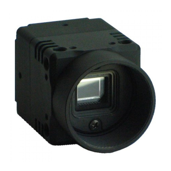
Monochrome / Color CMOS Camera
STC-MBE132U3V
STC-MCE132U3V
STC-MCE132U3V-C (1.3M / Color / C mount)
Product Specifications and User's Guide
STC-MBE132U3V / MCE132U3V / STC-MCE132U3V-C
Product Specifications and User's Guide
(1.3M / Monochrome CS mount)
(1.3M / Color / CS mount)
No.13S062-07
1/53
Advertisement
Table of Contents

Related Manuals for Omron STC-MBE132U3V


Summary of Contents for Omron STC-MBE132U3V
- Page 1 Monochrome / Color CMOS Camera STC-MBE132U3V (1.3M / Monochrome CS mount) STC-MCE132U3V (1.3M / Color / CS mount) STC-MCE132U3V-C (1.3M / Color / C mount) Product Specifications and User’s Guide STC-MBE132U3V / MCE132U3V / STC-MCE132U3V-C Product Specifications and User’s Guide 1/53...
-
Page 2: Table Of Contents
Item Numbers Naming Method ..........................7 Specifications .................................. 8 Electronic Specifications............................. 8 Spectral Sensitivity Characteristics .......................... 10 4.2.1 STC-MBE132U3V / STC-MCE132U3V / STC-MCE132U3V-C ................ 10 4.2.2 IR Cut Filter (STC-MCE132U3V / STC-MCE132u3V-C) .................. 10 Mechanical Specifications ............................11 4.3.1 STC-MBE132U3V / STC-MCE132U3V ......................11 4.3.2... - Page 3 EventControl ..............................50 9.16.7 EventExposureEndData ............................ 50 9.16.8 EventTestData ..............................50 9.16.9 AnalogControl ..............................50 9.16.10 LUTControl ..............................50 9.16.11 UserSetControl .............................. 51 9.16.12 TestControl ..............................51 Revision History ................................. 52 STC-MBE132U3V / MCE132U3V / STC-MCE132U3V-C Product Specifications and User’s Guide 3/53...
- Page 4 It is necessary to wiring with turn off the camera. It is necessary to mounting the camera without This will cause of electrification or malfunction. stress for the cable. This will case of electrification or fire. STC-MBE132U3V / MCE132U3V / STC-MCE132U3V-C Product Specifications and User’s Guide 4/53...
- Page 5 It is turn off the camera when maintaining or This will cause of fire, electrification or inspecting the camera. malfunction. This will cause of electrification. [Disposal] Caution It is necessary to dispose as industrial waste. STC-MBE132U3V / MCE132U3V / STC-MCE132U3V-C Product Specifications and User’s Guide 5/53...
-
Page 6: Product Precautions
Exchange or repair the malfunction camera if the malfunction is occurred by our responsibility. “Warranty” mean is warranty for the delivered camera itself. Please accept the induction damage by the camera malfunction is not included. STC-MBE132U3V / MCE132U3V / STC-MCE132U3V-C Product Specifications and User’s Guide 6/53... -
Page 7: Overview
・8bits, 10bits output (RGB8 output is available for color model) Item Numbers Naming Method STC-MxE132U3V-x None: CS mount C: C mount U3V: USB3 Vision 132: 1.3M Pixel, 1/1.8” Sensor Sensor Manufacturer e: e2V B: Mono Chrome C: Color STC-MBE132U3V / MCE132U3V / STC-MCE132U3V-C Product Specifications and User’s Guide 7/53... -
Page 8: Specifications
Horizontal / Vertical / Horizontal and Vertical / Off Defective Pixel Correction Up to 32 points Auto Image Auto Exposure Support Support Control Auto Gain Support Support Auto White Balance Support Default: Bold STC-MBE132U3V / MCE132U3V / STC-MCE132U3V-C Product Specifications and User’s Guide 8/53... - Page 9 USB host controller. This may resolve to increase the frame rate. PC resources may have consumed during the image processing (color interpolation, image display, etc.) with huge image data from camera. STC-MBE132U3V / MCE132U3V / STC-MCE132U3V-C Product Specifications and User’s Guide 9/53...
-
Page 10: Spectral Sensitivity Characteristics
No.13S062-07 Spectral Sensitivity Characteristics 4.2.1 STC-MBE132U3V / STC-MCE132U3V / STC-MCE132U3V-C 4.2.2 IR Cut Filter (STC-MCE132U3V / STC-MCE132u3V-C) Figure 1. IR Cut Filter Characteristics (STC-MBE132U3V) STC-MBE132U3V / MCE132U3V / STC-MCE132U3V-C Product Specifications and User’s Guide 10/53... -
Page 11: Mechanical Specifications
Camera Mounting M2 screw holes (Three on top, bottom and both side plate) M4 screws holes (Two on top, four on bottom plate) Weight Approximately 40 g (*1) Excluding connectors STC-MBE132U3V / MCE132U3V / STC-MCE132U3V-C Product Specifications and User’s Guide 11/53... -
Page 12: Environmental Specifications
(*1) Please insure the camera is installed with the appropriate heat dissipation. If camera has a mounted lens and a tripod with an aluminum plate, this could decrease the camera housing temperature for heat dissipation. Upper side of camera Measuring point STC-MBE132U3V / MCE132U3V / STC-MCE132U3V-C Product Specifications and User’s Guide 12/53... -
Page 13: Connector Specifications
USB OTG ID SSTX− SuperSpeed transmitter differential pair (−) SSTX+ SuperSpeed transmitter differential pair (+) SSRX− SuperSpeed receiver differential pair (−) SSRX+ SuperSpeed receiver differential pair (+) 12345 678910 STC-MBE132U3V / MCE132U3V / STC-MCE132U3V-C Product Specifications and User’s Guide 13/53... -
Page 14: I/O Connector
Input Signals Electronic Characteristics Input Signal / Input Voltage: 0 to +5 V Input Signal / Voltage Level High Level: +2.5 V (min.) Low Level: +0.7 V (max.) Input Signal Circuit STC-MBE132U3V / MCE132U3V / STC-MCE132U3V-C Product Specifications and User’s Guide 14/53... - Page 15 10k ohm IO_GND CUS03 (Toshiba) IO_GND Caution!! *The voltage applied on “input 1” or “input 2” must be less than or equal to 5 V, the absolute maximum input voltage. STC-MBE132U3V / MCE132U3V / STC-MCE132U3V-C Product Specifications and User’s Guide 15/53...
-
Page 16: Output Signals
1.82 µs 1.66 µs 1.60 µs 0.82 µs 0.84 µs 1.16 µs 1.44 µs 0.50 µs 0.56 µs 0.56 µs 0.70 µs 0.56 µs 0.66 µs 1.16 µs 2.04 µs STC-MBE132U3V / MCE132U3V / STC-MCE132U3V-C Product Specifications and User’s Guide 16/53... - Page 17 CAMERA IO_VCC 22k ohm USER OUTPUT 100 ohm OUTPUT DTC144EM (Rohm) CUS03 (Toshiba) IO_GND *The voltage applied on “IO_VCC” must be within the range of +3.3 to +24 V. STC-MBE132U3V / MCE132U3V / STC-MCE132U3V-C Product Specifications and User’s Guide 17/53...
- Page 18 *The voltage applied on “IO2” and “IO3” (USER_VCC) must be less than or equal to 24 V. *The incoming current to “IO2” and “IO3” (USER_VCC) must be less than or equal to 15 mA. STC-MBE132U3V / MCE132U3V / STC-MCE132U3V-C Product Specifications and User’s Guide...
-
Page 19: Dimensions
No.13S062-07 Dimensions STC-MBE132U3V / STC-MCE132U3V Unit: mm *How to Identify Monochrome and Color Camera STC-MBE132U3V STC-MCE132U3V STC-MBE132U3V / MCE132U3V / STC-MCE132U3V-C Product Specifications and User’s Guide 19/53... -
Page 20: Stc-Mce132U3V-C
No.13S062-07 STC-MCE132U3V-C Unit: mm STC-MBE132U3V / MCE132U3V / STC-MCE132U3V-C Product Specifications and User’s Guide 20/53... -
Page 21: Sensor Information
Pixel (n) of Data: nth pixel being transferred STC-MCE132U3V / STC-MCE132U3V-C (Color) Pixel00 Pixel01 Data Data Pixel10 Pixel11 Data Data Pixel (m, n) of Data: nth pixel of the mth line being transferred STC-MBE132U3V / MCE132U3V / STC-MCE132U3V-C Product Specifications and User’s Guide 21/53... -
Page 22: Image Acquisition And Camera Operational Modes (Genicam)
When Exposure Mode is set to Timed, the Exposure Time value will be set as the exposure time. ExposureTime 露光 Exposure VideoOut 映像出力 (*) The camera is set to Free run mode as the default mode. STC-MBE132U3V / MCE132U3V / STC-MCE132U3V-C Product Specifications and User’s Guide 22/53... -
Page 23: Trigger Mode
Trigger Mode On. (*) Please do not apply the Trigger through maximum frame rate on Trigger Mode. When Trigger applies within sensor Readout as exposure end, camera interrupted Readout. STC-MBE132U3V / MCE132U3V / STC-MCE132U3V-C Product Specifications and User’s Guide 23/53... -
Page 24: Frame Start Trigger (Edge Preset)
(Positive) I/O Delay (tIPDLH) I/O遅延(tIPDLH) Trigger Input (Negative) トリガー入力(負極性) I/O遅延(tIPDHL) I/O Delay (tIPDHL) LineDebounceTime TriggerDelay Trigger Delay Exposure Start Duration inside of sensor センサー内部の露光開始遅延 ExposureTime Exposure 露光 VideoOut 映像出力 STC-MBE132U3V / MCE132U3V / STC-MCE132U3V-C Product Specifications and User’s Guide 24/53... -
Page 25: Frame Start Trigger (Pulse Width Trigger)
This function can apply either external signal or a software command as the trigger. The software trigger can be applied through the “execute Trigger Software” command when the trigger is selected on the Trigger Selector. STC-MBE132U3V / MCE132U3V / STC-MCE132U3V-C Product Specifications and User’s Guide 25/53... -
Page 26: Io Function
This function monitors the signal status on the input Line. The High level (Line Status: true) or Low level (Line Status false) status can be seen through the software. STC-MBE132U3V / MCE132U3V / STC-MCE132U3V-C Product Specifications and User’s Guide 26/53... -
Page 27: Trigger Delay
“Trigger Out on Time (Output pulse width)” activation time signal with set “Trigger Out Delay (Output pulse delay time)” is output when one frame image transferring from camera was finished. STC-MBE132U3V / MCE132U3V / STC-MCE132U3V-C Product Specifications and User’s Guide... - Page 28 9) Exposure Active (In Exposure Period) The signal that activation time is exposure time is output. (*) Actual exposure period = Output signal pulse width + Minimum exposure time 13.73 seconds μ STC-MBE132U3V / MCE132U3V / STC-MCE132U3V-C Product Specifications and User’s Guide 28/53...
- Page 29 Transfer End Out (*) This timing chart does not include the delay of the IO circuit (*) The trigger port in this chart describes Frame Start trigger as an example STC-MBE132U3V / MCE132U3V / STC-MCE132U3V-C Product Specifications and User’s Guide 29/53...
-
Page 30: User Output
Integer Type Strobe Out Delay Time Range: 0 to 262,143 μseconds, Default: 30 μseconds StrobeOutOnTime Integer Type Strobe Out On Time Range: 4 to 262,143 μseconds, Default: 32 μseconds STC-MBE132U3V / MCE132U3V / STC-MCE132U3V-C Product Specifications and User’s Guide 30/53... -
Page 31: Camera Functions
Setting steps: 2 lines The parameters define as following chart. OffsetY Height ROI Region OffsetX Width (*) Width, Height, OffsetX, OffestY setting steps is the same in Binning and Decimation. STC-MBE132U3V / MCE132U3V / STC-MCE132U3V-C Product Specifications and User’s Guide 31/53... - Page 32 Width Setting range: 32 to 1,280 pixels Default: 1,280 pixels Setting steps 4 pixels unit Height Setting range: 32 to 1,024 pixels Default: 1,024 pixels Setting steps 4 lines STC-MBE132U3V / MCE132U3V / STC-MCE132U3V-C Product Specifications and User’s Guide 32/53...
-
Page 33: Pixel Format
1: Disable Binning 2: Binning 2 Pixel BinningVertical Integer Type Sets Binning on Vertical direction 1: Disable Binning 2: Binning 2 Pixel (*) Binning and Decimation function cannot be use simultaneously. STC-MBE132U3V / MCE132U3V / STC-MCE132U3V-C Product Specifications and User’s Guide 33/53... -
Page 34: Decimation
Sets decimation on vertical direction 1: Disable Decimation, 2: Decimate one of two pixels 4: Decimate three of four pixels (*) Binning and Decimation function cannot be use simultaneously. STC-MBE132U3V / MCE132U3V / STC-MCE132U3V-C Product Specifications and User’s Guide 34/53... -
Page 35: Image Flip
IBoolean Type Switch ON / OFF at Vertical False: Vertical Flip Off, True: Vertical Flip On. Default: False Reverse X(Off), Y(Off) Reverse X(Off), Y(On) Reverse X(On), Y(Off) Reverse X(On), Y(On) STC-MBE132U3V / MCE132U3V / STC-MCE132U3V-C Product Specifications and User’s Guide 35/53... - Page 36 No.13S062-07 Reverse X(Off), Y(Off) Reverse X(Off), Y(On) Reverse X(On), Y(Off) Reverse X(On), Y(On) (*) When the image is flipping for color camera, the pixel array is also flipped. STC-MBE132U3V / MCE132U3V / STC-MCE132U3V-C Product Specifications and User’s Guide 36/53...
-
Page 37: Gain
GenICam Parameters BalanceRatio[BalanceRatioSelector] IFloat Type White Balance Gain Range: 0 to 511, Default: Red: 248, Green: 128, Blue: 248 White Balance Gain Formula Gain (x times) = BalanceRatio[BalanceRatioSelector] / 128 STC-MBE132U3V / MCE132U3V / STC-MCE132U3V-C Product Specifications and User’s Guide 37/53... -
Page 38: Black Level
When AGC and auto exposure are enabled, at first, the brightness adjusts with auto exposure function. If the brightness does not achieve “Auto Light Target” brightness with auto exposure function, the brightness adjusts with the AGC function. STC-MBE132U3V / MCE132U3V / STC-MCE132U3V-C Product Specifications and User’s Guide 38/53... -
Page 39: Agc (Auto Gain Control)
Sets “Exposure Auto Limit Min” (When using Auto Exposure) Sets “Continuous” at “Gain Auto” (When using AGC) Sets “Gain Auto Limit Max” (When using AGC) Sets “Gain Auto Limit Min” (When using AGC) STC-MBE132U3V / MCE132U3V / STC-MCE132U3V-C Product Specifications and User’s Guide 39/53... -
Page 40: White Balance (Only Available For The Color Model)
Sets value at “Balance Ratio” Sets “Off” at “Balance White Auto” 9.9.4 Auto White Balance (Continuous) Optimizes white balance gain each frame automatically. Setting Procedure 1. Sets “Continuous” at “Balance White Auto” STC-MBE132U3V / MCE132U3V / STC-MCE132U3V-C Product Specifications and User’s Guide 40/53... -
Page 41: Push To Set White Balance (Once)
Sets “Off” at “Balance White Auto” automatically after set “White Balance Gain”. Setting Procedure Sets the flat white target (To process white balance correctly) Sets Once on Balance White Auto STC-MBE132U3V / MCE132U3V / STC-MCE132U3V-C Product Specifications and User’s Guide 41/53... -
Page 42: Gamma Table
The between the points is generates by the linear interpolation. For 10bits image (Gamma = 2.0) 1024 B point Gamma Table A point Generate by the linear interpolation with A point and B point. 1024 Input data 入力データ STC-MBE132U3V / MCE132U3V / STC-MCE132U3V-C Product Specifications and User’s Guide 42/53... -
Page 43: Save And Load The Camera Settings
ROM that is selected at Setting UserSetSelector. Caution: Default UserSetSave cannot execute when “Default” Selector was selected at “UserSet Selector” UserSetSelector Setting Procedure 1. Selects “UserSetX” at “UserSetSelector” 2. Execute “UserSetSave” STC-MBE132U3V / MCE132U3V / STC-MCE132U3V-C Product Specifications and User’s Guide 43/53... -
Page 44: Loading Camera Settings
Set “UserSetX” or “Default” at “UserSetDefault” 9.11.4 Camera Settings Initialization Please follow the below procedure for the camera settings put back to the factory default settings. Setting Procedure Selects “Default” at “UserSetSelector”. Executes “UserSetLoad”. STC-MBE132U3V / MCE132U3V / STC-MCE132U3V-C Product Specifications and User’s Guide 44/53... -
Page 45: Pixel Defect Correction
When the external hardware or software signal is input to the camera, the following process are proceeding. Line0 Line Line1 Debouncer Trigger Trigger Trigger トリガー Selector Delay Line2 Software Trigger Trigger Source STC-MBE132U3V / MCE132U3V / STC-MCE132U3V-C Product Specifications and User’s Guide 45/53... -
Page 46: Device User Id
Send notification as event when expose finishes in the camera. Event ID is 0x9001. (*) The event occurrence frequently, the stream data transferring rate could be reduced because Event and Stream (image data) share USB bus. STC-MBE132U3V / MCE132U3V / STC-MCE132U3V-C Product Specifications and User’s Guide 46/53... -
Page 47: Genicam Command List
Announce the end of registers streaming. This will do a register set validation for consistency and activate it. TimestampLatch Latches the current timestamp counter into TimestampLatchValue. TimestampLatchValue Returns the latched value of the timestamp counter. STC-MBE132U3V / MCE132U3V / STC-MCE132U3V-C Product Specifications and User’s Guide 47/53... -
Page 48: Imageformatcontrol
This feature is used to flip horizontally the image sent by the device. The AOI is applied after the flipping. ReverseY This feature is used to flip vertically the image sent by the device. The AOI is applied after the flipping. STC-MBE132U3V / MCE132U3V / STC-MCE132U3V-C Product Specifications and User’s Guide 48/53... -
Page 49: Acquisitioncontrol
Duration of StrobeOut signal when LineSource is set to StrobeOut(us). TriggerOutDelay Delay of TriggerOut signal when LineSource is set to TriggerOut(us). TriggerOutOnTime Duration of TriggerOut signal when LineSource is set to TriggerOut(us). STC-MBE132U3V / MCE132U3V / STC-MCE132U3V-C Product Specifications and User’s Guide 49/53... -
Page 50: Eventcontrol
Determine index of targeted pixel for pixel correction. PixelCorrectionEnabled Determine if targeted pixel is enabled for pixel correction. PixelCorrectionX Determine x-coordinate of targeted pixel for pixel correction. PixelCorrectionY Determine y-coordinate of targeted pixel for pixel correction. STC-MBE132U3V / MCE132U3V / STC-MCE132U3V-C Product Specifications and User’s Guide 50/53... -
Page 51: Usersetcontrol
TestPendingAck before acknowledging the write. TestEventGenerate Generates a Test Event. TriggerEventTest This register is used to control the generation of test events. STC-MBE132U3V / MCE132U3V / STC-MCE132U3V-C Product Specifications and User’s Guide 51/53... -
Page 52: Revision History
Added trademark information USB3 Vision is trademark of AIA. GenICam is trademark of EMVA. Other company names and product names in this document are trademarks of their respective owners. STC-MBE132U3V / MCE132U3V / STC-MCE132U3V-C Product Specifications and User’s Guide 52/53... - Page 53 No.13S062-07 19F, Ebina Prime Tower 9-50, Chuo 2 chome Ebina-city, Kanagawa 243-0432 Japan TEL +81-46-236-6660 FAX +81-46-236-6661 URL http://www.sentech.co.jp/ STC-MBE132U3V / MCE132U3V / STC-MCE132U3V-C Product Specifications and User’s Guide 53/53...
Need help?
Do you have a question about the STC-MBE132U3V and is the answer not in the manual?
Questions and answers