
Related Manuals for Omron FHV Series


Summary of Contents for Omron FHV Series
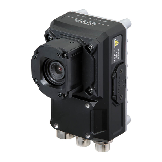
- Page 1 Vision Sensor FHV Series Smart Camera Setup Manual FHV7H-££££ Z408-E1-01...
- Page 2 No patent liability is assumed with respect to the use of the information contained herein. Moreover, because OMRON is constantly striving to improve its high-quality products, the information con- tained in this manual is subject to change without notice. Every precaution has been taken in the preparation of this manual.
-
Page 3: Intended Audience
Introduction Thank you for purchasing the FHV Series Smart Camera. This manual contains information that is necessary to use the FHV Series Smart Camera. Please read this manual and make sure you understand the functionality and performance of the FHV Series Smart Camera before you attempt to use it in a control system. -
Page 4: Relevant Manuals
Setup the communication setting of Smart Camera EtherNet/IP PROFINET Ethernet RS-232C Parallel interface Setup the Smart Camera EtherNet/IP PROFINET Ethernet RS-232C Parallel interface Create and Set the Scene EtherNet/IP PROFINET Ethernet RS-232C Parallel interface FHV Series Smart Camera Setup Manual (Z408-E1) - Page 5 Information Reference Matrix Optimizing the Scene Flow EtherNet/IP PROFINET Ethernet RS-232C Parallel interface Connecting the Controller EtherNet/IP PROFINET Ethernet RS-232C Parallel interface Using Helpful Functions EtherNet/IP PROFINET Ethernet RS-232C Parallel interface Troubleshooting and Problem Solving FHV Series Smart Camera Setup Manual (Z408-E1)
-
Page 6: Manual Structure
Unit connectors. precautions, additional information, or reference information. Manual name NJ-series CPU Unit Hardware User’s Manual (W500) Note This illustration is provided only as a sample. It may not literally appear in this manual. FHV Series Smart Camera Setup Manual (Z408-E1) -
Page 7: Special Information
Precautions on what to do and what not to do to ensure proper operation and performance. Additional Information Additional information to read as required. This information is provided to increase understanding or make operation easier. FHV Series Smart Camera Setup Manual (Z408-E1) - Page 8 FHV Series Smart Camera Setup Manual (Z408-E1)
-
Page 9: Table Of Contents
Symbols and the Meanings for Safety Precautions Described in This Manual ..........13 Meanings of Alert Symbols ..........................13 Warning................................14 Precautions for Safe Use ..................15 Condition of the Fitness of OMRON Products ....................15 Installation Environment ..........................15 Power Supply and Wiring ..........................15 Mounting ................................16 Others ................................17... - Page 10 Specfications ...........................3 - 46 3-8-2 Dimensions ..........................3 - 46 Software..........................3 - 48 3-9-1 Remote Operation Tool ......................3 - 48 3-9-2 Simulation Software ........................3 - 48 Section 4 Handling and Installation Environment Warning..........................4 - 2 FHV Series Smart Camera Setup Manual (Z408-E1)
- Page 11 Fail-safe Measures.......................6 - 4 Precautions for I/O Interface....................6 - 5 I/O Cable Interface (Power Supply, I/O, RS-232C).............6 - 6 6-4-1 Recommended Power Supply for FHV Series ................6 - 6 6-4-2 Cables ............................6 - 7 6-4-3 Pin Layout ..........................6 - 8 6-4-4 Interface Specifications ......................6 - 9...
-
Page 12: Terms And Conditions Agreement
Omron’s exclusive warranty is that the Products will be free from defects in materials and work- manship for a period of twelve months from the date of sale by Omron (or such other period ex- pressed in writing by Omron). Omron disclaims all other warranties, express or implied. -
Page 13: Application Considerations
WAY CONNECTED WITH THE PRODUCTS, WHETHER SUCH CLAIM IS BASED IN CONTRACT, WARRANTY, NEGLIGENCE OR STRICT LIABILITY. Further, in no event shall liability of Omron Companies exceed the individual price of the Product on which liability is asserted. Application Considerations... - Page 14 Product. Errors and Omissions Information presented by Omron Companies has been checked and is believed to be accurate; how- ever, no responsibility is assumed for clerical, typographical or proofreading errors or omissions. FHV Series Smart Camera Setup Manual (Z408-E1)
-
Page 15: Safety Precautions
Indicates the possible danger of electric shock under specific conditions. LED light Hazard Indicates the possible danger of LED radiation or light. High Temperature Caution Indicates the possible danger of injury by high temperature under specific condi- tions. FHV Series Smart Camera Setup Manual (Z408-E1) -
Page 16: Warning
OFF, since it remains extremely hot. When mounting the lighting module, lens module, and covers, make sure that the screws are tightened securely. If not, the product may break or malfunction, or injury may result. FHV Series Smart Camera Setup Manual (Z408-E1) -
Page 17: Precautions For Safe Use
Applications under conditions and environment not described in specifications. (1) In addition to the applications listed from (a) to (d) above, Omron products (see definition) are not intended for use in vehicles designed human transport (including two wheel vehicles). Please do NOT use Omron products for vehicles designed human transport. -
Page 18: Mounting
- When attaching the lighting module, use S8VK-G12024 (OMRON) or S8VS-12024 (OMRON). - When not attaching the lighting module, use S8VK-G06024 (OMRON) or S8VS-06024 (OMRON). • Wire high-voltage cables or power cables separately from the cables of this product. If the same ca- ble or duct is used, the product may receive induction and it may cause malfunctioning or breakage. -
Page 19: Others
• If anything abnormal occurs, for example, strange smell/sound is detected, the main unit gets very hot, or a smoke comes, stop using the product, turn OFF the product, and consult OMRON’s branch or sales office. -
Page 20: Precautions For Correct Use
Camera main unit is turned on for a while. Remove the card after confirming that the LED is com- pletely turned off. • Except when inserting or removing the microSD card, put the cover of the microSD card inserting connector and screw it up before using the product. FHV Series Smart Camera Setup Manual (Z408-E1) -
Page 21: Maintenance
Communications with Upper Equipment • Implement communications with upper equipment after confirming that this product has been started up. In addition, when this product is being started up, unstable signals may be issued by the upper FHV Series Smart Camera Setup Manual (Z408-E1) -
Page 22: Failsafe Measures
Do not remve them from the product. • When turning on the FHV series, the date/time settings always returns to the default. Therefore, you need to re-set the date/time with an operation or a communication command every time at startup. -
Page 23: Led Safety
Display FHV-LTM-W White Risk group 2 FHV-LTM-R Risk group 1 FHV-LTM-IR Infrared light Risk group 1 Risk group 1 Green Risk group 2 FHV-LTM-MC Blue Risk group 2 Infrared light Risk group 1 FHV Series Smart Camera Setup Manual (Z408-E1) -
Page 24: Regulations And Standards
• EU Directive 2014/30/EU (After April 20 2016)/EU EN61326-1 Electromagnetic environment : Industrial electromagnetic environment (EN/IEC 61326-1 Table 2) • This product complies with EC/EU Directives. EMC-related performance of the OMRON devices that comply with EC/EU Directives will vary depending on the configuration, wiring, and other conditions of the equipment or control panel on which the OMRON devices are installed. -
Page 25: Related Manuals
FHV7£-££££-S-££-££ nications Settings FH/FHV/FZ5 series and PLCs. The following communications proto- FZ5-L35£ col are described. FZ5-L35£-££ Parallel, PLC Link, EtherNet/IP, FZ5-6££ EtherCAT, and Non-procedure. FZ5-6££-££ FZ5-8££ FZ5-8££-££ FZ5-11££ FZ5-11££-££ FZ5-12££ FZ5-12££-££ FHV Series Smart Camera Setup Manual (Z408-E1) -
Page 26: Terminology
However, you can select Output in Test measurement to output the measurement results after executing measurements. Single measurement A measurement that is executed only once in synchronization with the trigger input. Continuous measurement Measurements are executed repeatedly and automatically without a trigger input. FHV Series Smart Camera Setup Manual (Z408-E1) - Page 27 You can check whether image input processing has been completed with the status of the READY signal. Even if the READY signal is ON when measurement proc- essing is being executed, the next STEP signal can be acknowledged. FHV Series Smart Camera Setup Manual (Z408-E1)
- Page 28 Ref. setting. Model The image pattern that serves as the inspection target. Characteristics portions are extracted from images of the object and registered as model registration. FHV Series Smart Camera Setup Manual (Z408-E1)
- Page 29 When 1: Negative number The advantage of two's complement numbers is that positive and negative num- bers can be used as is in calculations. Ex. When -1+10=9 11111111 (= -1) +)00001010 (= 10) 00001001 (= 9) FHV Series Smart Camera Setup Manual (Z408-E1)
-
Page 30: Revision History
A manual revision code appears as a suffix to the catalog number on the front and back covers of the manual. Z408-E1-01 Cat. No. Revision code Revision code Date Revised content Nov. 2018 Original production FHV Series Smart Camera Setup Manual (Z408-E1) - Page 31 Sections in This Manual Sections in This Manual Confirm the Package Overview of FHV series Configuration Handling and Installation Environment Installation Power Supply and I/O Interface Software Setup Index FHV Series Smart Camera Setup Manual (Z408-E1)
- Page 32 Sections in This Manual FHV Series Smart Camera Setup Manual (Z408-E1)
- Page 33 Cables......................1 - 4 1-2-2 Modules ......................1 - 5 1-2-3 Accessories ....................1 - 6 1-2-4 Lighting and Lighting Controller ..............1 - 8 1-2-5 Software......................1 - 8 1 - 1 FHV Series Smart Camera Setup Manual (Z408-E1)
-
Page 34: Smart Camera
• Connector cap for an external lighting (mounted on the body): 1 • Special cover for FHV-LEM-S (mounted on the body): 1 • Instruction sheet: 1 each (Body, and lens module) • Membership registration: 1 • Compliance sheet: 1 1 - 2 FHV Series Smart Camera Setup Manual (Z408-E1) - Page 35 • Connector cap for an external lighting (mounted on the body): 1 • Instruction sheet: 1 each (Body, lens module, and lighting module) • Membership registration: 1 • Compliance sheet: 1 1 - 3 FHV Series Smart Camera Setup Manual (Z408-E1)
-
Page 36: Sold Separately
FHV-VNB □□M Cable length: 2 m, 3 m, 5 m, 10 m, 20 m Ethernet cable right-angle FHV-VNLB □□M Cable length: 2 m, 3 m, 5 m, 10 m, 20 m 1 - 4 FHV Series Smart Camera Setup Manual (Z408-E1) -
Page 37: Modules
IR:Typ. 850 nm • Instruction sheet: 1 • Compliance sheet: 1 If purchasing the Smart Camera with integrated lighting module, refer to the 1-1-3 FHV7H-□□□□□- S□□-□□ Series on page 1 - 3. 1 - 5 FHV Series Smart Camera Setup Manual (Z408-E1) -
Page 38: Accessories
For Smart Camera body FHV-XMT-7 None and lighting controller mounting For lighting controller FHV-XMT-7-TCC Screws: M5×8 mm: 5 mounting Waterproof Packings Appearance Description Model FHV-XWP-CAM For camera: 5 FHV-XWP-LTM For internal lighting: 5 1 - 6 FHV Series Smart Camera Setup Manual (Z408-E1) - Page 39 FHV-XWC-ECN Light-shielding Sheet Appearance Description Model FHV-XLS-LTM For lighting module: 3 After this was used once, replace this with the new one when mounting and dismounting lens or lighting module. 1 - 7 FHV Series Smart Camera Setup Manual (Z408-E1)
-
Page 40: Lighting And Lighting Controller
The Remote Operation tool and the simulation software are possible to download with free by doing the member registration after purchasing the Smart Camera. For details, refer to the membership reg- istration sheet packed with the Smart Camera. 1 - 8 FHV Series Smart Camera Setup Manual (Z408-E1) -
Page 41: Overview Of Fhv Series
Overview of FHV Series Overview of System ..................2 - 2 2-1-1 Basic System of Measurement ..............2 - 2 Flow of Use Procedure ................2 - 7 2 - 1 FHV Series Smart Camera Setup Manual (Z408-E1) -
Page 42: Overview Of System
2-1-1 Basic System of Measurement FHV series use pre-built packages that contain all the processing tasks (for image input, measurement processing, displays, outputs, etc.) that are required for vision inspections. Users arrange these packaged processes to make measurement flows with in order of execution of the vision inspection. - Page 43 The measurement flow is executed basically in order of the unit numbers. In the measurement flow, you can change the processing to execute based on the inspection results or input conditions of the vision inspection. 2 - 3 FHV Series Smart Camera Setup Manual (Z408-E1)
- Page 44 OMRON IPC (NY) Panel computer Switching Hub Ethernet Cable ・FHV-VN(L)B □ M □ ・PC (Remote Operation Tool) OMRON PLC NJ/NX/CJ Other company PLC FLV series Lighting External Controller Lighting FL series 2 - 4 FHV Series Smart Camera Setup Manual (Z408-E1)
- Page 45 09: 9 [mm] • 12: 12 [mm] • 16: 16 [mm] • 25: 25 [mm] • ⑥ Lighting color W: White • R: Red • IR: Infrared light • MC: Multi color 2 - 5 FHV Series Smart Camera Setup Manual (Z408-E1)
- Page 46 □□□□□- module/IP40 3.2Mpix FHV7H- FHV-LEM- S□□ 6.3Mpix □016-□ S□□ IP67 Lens FHV7H- module/IP67 □032-□ FHV-XHD- FHV7H- □063R-□ FHV-LTM- IP67 FHV7H- Lens module □□ □□□□□- /Internal S□□-□□ lighing - IP67 2 - 6 FHV Series Smart Camera Setup Manual (Z408-E1)
-
Page 47: Flow Of Use Procedure
Select Tool - System settings , Vision System FH/FHV/FZ5 series and then set Camera, User's Manual Communication and Other. ↓ Click Data save. Vision System FH/FHV/FZ5 series User's Manual ↓ 2 - 7 FHV Series Smart Camera Setup Manual (Z408-E1) - Page 48 PLC, User's Manual such as measurement trigger com- mands. ↓ Management and Analysis Save and analyze measurement Vision System FH/FHV/FZ5 series data and images. User's Manual 2 - 8 FHV Series Smart Camera Setup Manual (Z408-E1)
-
Page 49: Configuration
3-8-1 Specfications ....................3 - 46 3-8-2 Dimensions ....................3 - 46 Software ...................... 3 - 48 3-9-1 Remote Operation Tool................3 - 48 3-9-2 Simulation Software..................3 - 48 3 - 1 FHV Series Smart Camera Setup Manual (Z408-E1) -
Page 50: Smart Camera
UI operation Remote Operation Tool Setup Create the processing flow using Flow editing. Language Japanese, English, Simplified Chinese, Traditional Chinese, German, French, Italian, Span- ish, Korean, Vietnamese, Polish 3 - 2 FHV Series Smart Camera Setup Manual (Z408-E1) - Page 51 (18.0 ms) (28.0 ms) (16.7 ms) (25.0 ms) acquisition time) Lens C mount mounting Field of Selecting a lens according to the field of view and installation distance view, Installation distance 3 - 3 FHV Series Smart Camera Setup Manual (Z408-E1)
- Page 52 Direct infusion: 1kV, Pulse rising: 5 ns, Pulse width: 50 ns, Burst continuation time: 15 ms/ 0.75 ms, Period: 300 ms, Application time: 1 min. Grounding Class D grounding (100Ω or less grounding resistance) * Existing the third class grounding 3 - 4 FHV Series Smart Camera Setup Manual (Z408-E1)
- Page 53 C mount cover (mounted on the body): 1 • Instruction sheet: 1 • Membership registration: 1 • Compliance sheet: 1 The number of scenes can be increased up to 1,024 with the Conversion scene group data tool. 3 - 5 FHV Series Smart Camera Setup Manual (Z408-E1)
- Page 54 (white) Connector for lens module (Black) Use this connector when mounting the lens module. Mounting screw holes Use them to screw up the smart camera. Recommended tightening torque : 2.3N・m 3 - 6 FHV Series Smart Camera Setup Manual (Z408-E1)
- Page 55 4-M5.0 depth 6 4-M5.0 depth 4 35.5 36.0 22.5 12.2 55.5 20.5 36.0 50.0 Mounting screw holes (The tolerance: ± 0.1 mm) Recommenden tightening torque: 2.3N ・ m (Unit: mm) 3 - 7 FHV Series Smart Camera Setup Manual (Z408-E1)
- Page 56 4-M5.0 depth 6 4-M5.0 depth 4 35.5 36.0 22.5 12.2 55.5 20.5 36.0 50.0 Mounting screw holes (The tolerance: ± 0.1 mm) Recommenden tightening torque: 2.3N ・ m (Unit: mm) 3 - 8 FHV Series Smart Camera Setup Manual (Z408-E1)
- Page 57 Mounting screw holes (The tolerance: ± 0.1 mm) Recommenden tightening torque: 2.3N ・ m (Unit: mm) Additional Information We have the 2D CAD data or 3D CAD data. You can download CAD data from www.fa.omron.co.jp. 3 - 9 FHV Series Smart Camera Setup Manual (Z408-E1)
-
Page 58: Cables
Bending resistance cable Connector type Right angle connector Size Power line AWG21 Others AWG26 Outer diameter 9.0±0.3 mm dia. Min. bending radius Fixed use: 54 mm, Sliding use: 72 mm 3 - 10 FHV Series Smart Camera Setup Manual (Z408-E1) - Page 59 , Test direction: 6 directions, three time each (up/down, ance front/behind, left/right) Material Mold part: Nylon, Thermoplastic polyurethane, Sheath part: PVC Weight Approx. 270 g Approx. 390 g Approx. 620 g Approx. 1200 Approx. 2350 3 - 11 FHV Series Smart Camera Setup Manual (Z408-E1)
- Page 60 • I/O cable (Right angle) 48.45 40.20 M12x1 15 dia. (Unit: mm) Additional Information We have the 2D CAD data or 3D CAD data. You can download CAD data from www.fa.omron.co.jp. 3 - 12 FHV Series Smart Camera Setup Manual (Z408-E1)
-
Page 61: Ethernet Cables
X/Y/Z, Sweep time: 8 minute/count, Sweep count: 10 Shock Impact force: 150 m/s , Test direction: 6 directions, three time each (up/down, resistance front/behind, left/right) Material Mold part: Nylon, Thermoplastic polyurethane, Sheath part: Polyurethane 3 - 13 FHV Series Smart Camera Setup Manual (Z408-E1) - Page 62 • Ethernet cable (Right angle) 48.45 53.50 M12 x 1 15 dia. (Unit: mm) Additional Information We have the 2D CAD data or 3D CAD data. You can download CAD data from www.fa.omron.co.jp. 3 - 14 FHV Series Smart Camera Setup Manual (Z408-E1)
-
Page 63: Lens Modules
Screws: M3×8 mm: 5 (including one spare piece) • Instruction sheet : 1 • Compliance sheet: 1 When the lens module is mounted to the product, the specificatins of vibration tolerance are changed. 3 - 15 FHV Series Smart Camera Setup Manual (Z408-E1) - Page 64 3 Configuration Dimensions 13.8 12.5 9.81 (Unit: mm) Additional Information We have the 2D CAD data or 3D CAD data. You can download CAD data from www.fa.omron.co.jp. 3 - 16 FHV Series Smart Camera Setup Manual (Z408-E1)
-
Page 65: Meaning Of Optical Chart
Select the model by confirming the field of view and camera installation distance on the optical diagram. In addition, the field of view may vary product by product. When mounting this product, be sure to confirm video using the monitor. 3 - 17 FHV Series Smart Camera Setup Manual (Z408-E1) - Page 66 Optical Chart • FHV7H-□004, FHV7H-□016 1,000 FHV-LEM-S25 FHV-LEM-S16 FHV-LEM-S12 FHV-LEM-S09 FHV-LEM-S06 1,000 Y field of view (mm) • FHV7H-□032 1,000 FHV-LEM-S25 FHV-LEM-S16 FHV-LEM-S12 FHV-LEM-S09 FHV-LEM-S06 1,000 Y field of view (mm) 3 - 18 FHV Series Smart Camera Setup Manual (Z408-E1)
- Page 67 3 Configuration • FHV7H-□063R 1,000 FHV-LEM-S25 FHV-LEM-S16 FHV-LEM-S12 FHV-LEM-S09 FHV-LEM-S06 1,000 Y field of view (mm) 3 - 19 FHV Series Smart Camera Setup Manual (Z408-E1)
-
Page 68: C Mount Lenses
Focal length [mm] Aperture(F No.) 1.8 to Close 2.7 to Close 3.5 to Close Filter size M30.5 P0.5 M30.5 P0.5 M30.5 P0.5 Max. sensor size 1/3-inch 1/3-inch 1/3-inch Mount C mount 3 - 20 FHV Series Smart Camera Setup Manual (Z408-E1) - Page 69 SV-10028H Appearance/ Dimensions [mm] 39 dia. 66.5 [WD:∞] to 71.6 [WD:2000] Focal length [mm] Aperture(F No.) 2.8 to Close Filter size M37.5 P0.5 Max. sensor size 1-inch Mount C mount 3 - 21 FHV Series Smart Camera Setup Manual (Z408-E1)
- Page 70 M27.0 P0.5 Optical 0.01x 0.03x 0.06x magnification Aperture (fixed F No.) Depth of field 1840.0 4560.0 6480.0 204.4 515.6 728.9 51.1 131.1 188.9 [mm] Maximum sensor 1/2-inch size Mount C mount 3 - 22 FHV Series Smart Camera Setup Manual (Z408-E1)
- Page 71 15 mm Filter size M27.0 P0.5 Optical 0.03x 0.20x 0.30x magnification Aperture (fixed F No.) Depth of field 186.7 515.6 728.9 13.4 19.2 [mm] Maximum sensor 2/3-inch size Mount C mount 3 - 23 FHV Series Smart Camera Setup Manual (Z408-E1)
- Page 72 25 mm Filter size M27.0 P0.5 Optical 0.05x 0.25x 0.50x magnification Aperture (fixed F No.) Depth of field 67.2 188.8 268.8 12.8 [mm] Maximum sensor 2/3-inch size Mount C mount 3 - 24 FHV Series Smart Camera Setup Manual (Z408-E1)
- Page 73 Focal length [mm] 35 mm Filter size M27.0 P0.5 Optical 0.26x 0.30x 0.65x magnification Aperture (fixed F No.) Depth of field 12.0 [mm] Maximum sensor 2/3-inch size Mount C mount 3 - 25 FHV Series Smart Camera Setup Manual (Z408-E1)
- Page 74 Mount C mount Insert the aperture into □□□□ in the model number as follows. F=2: Blank F=5: F5.6 F=8: F8 When an allowable diameter of confusion circle is 0.04 mm 3 - 26 FHV Series Smart Camera Setup Manual (Z408-E1)
- Page 75 WD [mm] Effective F No. 11.8 11.97 13.6 13.5 0.43 0.27 Depth of field [mm] 5.24 5.33 4.53 4.53 Resolution [μm] TV distortion 0.01% 0.02% 0.03% 0.03% Max. sensor size 2/3-inch 3 - 27 FHV Series Smart Camera Setup Manual (Z408-E1)
- Page 76 (vibration/shock). When fixing the lens, insulate the lens from the fixture. (2) The above specifications are values calculated from the optical design and can vary depending on installation conditions. 3 - 28 FHV Series Smart Camera Setup Manual (Z408-E1)
- Page 77 The working distance is from the end of the lens to the sensor. The resolution is calculated using a wavelength of 550 nm. The depth of field is calculated using an allowable diameter of confusion circle of 0.04 mm. 3 - 29 FHV Series Smart Camera Setup Manual (Z408-E1)
-
Page 78: Meaning Of Optical Chart
Select the model by confirming the field of view and camera installation distance on the optical diagram. In addition, the field of view may vary product by product. When mounting this product, be sure to confirm video using the monitor. 3 - 30 FHV Series Smart Camera Setup Manual (Z408-E1) - Page 79 Y field of view (mm) (b) Smart camera: FHV7H-□004, FHV7H-□016 (for 3Z4S-LE SV-H series) 5,000 3Z4S-LE SV-10028H 1,000 SV-7525H SV-5014H SV-3514H SV-2514H SV-1614H SV-1214H SV-0814H SV-0614H 1,000 Y field of view (mm) 3 - 31 FHV Series Smart Camera Setup Manual (Z408-E1)
- Page 80 Y field of view (mm) (d) Smart camera: FHV7H-□050 (for 3Z4S-LE SV-H series) 5,000 3Z4S-LE SV-10028H SV-7525H 1,000 SV-5014H SV-3514H SV-2514H SV-1614H SV-1214H SV-0814H SV-0614H 1,000 Y field of view (mm) 3 - 32 FHV Series Smart Camera Setup Manual (Z408-E1)
- Page 81 Y field of view (mm) (f) Smart camera: FHV7H-□120R (for 3Z4S-LE SV-H series) 5,000 3Z4S-LE SV-10028H 1,000 SV-7525H SV-5014H SV-3514H SV-2514H SV-1614H SV-1214H SV-0814H SV-0614H 1,000 Y field of view (mm) 3 - 33 FHV Series Smart Camera Setup Manual (Z408-E1)
- Page 82 VS-MCA6.5 VS-MCA4 1,000 Y field of view (mm) (b) Smart camera: FHV7H-□032 (for 3Z4S-LE VS-MCA series) 1,000 VS-MCA75 VS-MCA50 VS-MCA35 VS-MCA30 VS-MCA25 VS-MCA20 VS-MCA15 1,000 Y field of view (mm) 3 - 34 FHV Series Smart Camera Setup Manual (Z408-E1)
- Page 83 VS-MCA20 VS-MCA15 1,000 Y field of view (mm) (d) Smart camera: FHV7H-□063R (for 3Z4S-LE VS-MCA series) 1,000 VS-MCA75 VS-MCA50 VS-MCA35 VS-MCA30 VS-MCA25 VS-MCA20 VS-MCA15 1,000 Y field of view (mm) 3 - 35 FHV Series Smart Camera Setup Manual (Z408-E1)
- Page 84 3 Configuration (e) Smart camera: FHV7H-□120R (for 3Z4S-LE VS-MCA series) 1,000 VS-MCA75 VS-MCA50 VS-MCA35 VS-MCA30 VS-MCA25 VS-MCA20 VS-MCA15 1,000 Y field of view (mm) 3 - 36 FHV Series Smart Camera Setup Manual (Z408-E1)
-
Page 85: Lighting Modules
Waterproof packing (large) FHV-XWP-LTM: 1 • Light shielding sheet FHV-XLS-LTM: 1 • Lighting cover FHV-XCV: 1 • Hexagonal wrench (length: 60 mm): 1 • Instruction sheet: 1 • Compliance sheet: 1 3 - 37 FHV Series Smart Camera Setup Manual (Z408-E1) - Page 86 3 Configuration 3-5-2 Dimensions (Unit: mm) Additional Information We have the 2D CAD data or 3D CAD data. You can download CAD data from www.fa.omron.co.jp. 3 - 38 FHV Series Smart Camera Setup Manual (Z408-E1)
-
Page 87: Specifications
, Test direction: 6 directions, three time each (up/down, front/ behind, left/right) Material Aluminum (A6061), polycarbonate Weight Approx. 70 g Approx. 70 g Approx. 70 g Approx. 70 g 3-6-2 Dimensions 10.7 (Unit: mm) 3 - 39 FHV Series Smart Camera Setup Manual (Z408-E1) - Page 88 3 Configuration Additional Information We have the 2D CAD data or 3D CAD data. You can download CAD data from www.fa.omron.co.jp. 3 - 40 FHV Series Smart Camera Setup Manual (Z408-E1)
-
Page 89: Specifications
, Test direction: 6 directions, three time each (up/ down, front/behind, left/right) Material Aluminum (A6061), polycarbonate Weight Approx. 220 g Approx. 220 g Approx. 220 g This is not available in FHV7H-□050、FHV7H-□063R、FHV7H-□120R. This is not available in FHV7H-□050. 3 - 41 FHV Series Smart Camera Setup Manual (Z408-E1) -
Page 90: Dimensions
3 Configuration 3-7-2 Dimensions • FHV-XHD-S M52x0.75 DEPTH2.5 ( 62.4 ) (Unit: mm) • FHV-XHD-L M52x0.75 DEPTH2.5 ( 85.4 ) (Unit: mm) 3 - 42 FHV Series Smart Camera Setup Manual (Z408-E1) - Page 91 4-M5.0 depth 6 depth 4 4-M5.0 35.5 36.0 22.5 12.2 55.5 20.5 36.0 50.0 Mounting screw holes (The tolerance: ± 0.1 mm) Recommenden tightening torque: 2.3N ・ m (Unit: mm) 3 - 43 FHV Series Smart Camera Setup Manual (Z408-E1)
- Page 92 4-M5.0 depth 6 4-M5.0 depth 4 35.5 36.0 22.5 12.2 55.5 20.5 36.0 50.0 Mounting screw holes (The tolerance: ± 0.1 mm) Recommenden tightening torque: 2.3N ・ m (Unit: mm) 3 - 44 FHV Series Smart Camera Setup Manual (Z408-E1)
- Page 93 3 Configuration Additional Information We have the 2D CAD data or 3D CAD data. You can download CAD data from www.fa.omron.co.jp. 3 - 45 FHV Series Smart Camera Setup Manual (Z408-E1)
-
Page 94: Mounting Fixtures
Approx. 220 g Approx. 50 g 3-8-2 Dimensions • FHV-XMT-7 77.2 +0.1 8-5.2 dia. 36 ±0.05 +0.1 dia. 12-M 2 6-M 4 4-M 5 56.8 1/4-20 UNC 89.6 98 ±0.05 (Unit: mm) 3 - 46 FHV Series Smart Camera Setup Manual (Z408-E1) - Page 95 3 Configuration • FHV-XMT-7-TCC 89.6 36 ±0.05 12-M2 (Unit: mm) Additional Information We have the 2D CAD data or 3D CAD data. You can download CAD data from www.fa.omron.co.jp. 3 - 47 FHV Series Smart Camera Setup Manual (Z408-E1)
-
Page 96: Software
3-9-1 Remote Operation Tool This Remote Operation tool supports Smart Camera of all FHV series. It is used to set conditions for inspection and measurement, and output image processing results according to the set conditions. You can download the simulation software with free by registering as our member after purchasing. -
Page 97: Handling And Installation Environment
Handling and Installation Environ- ment Warning ......................4 - 2 4 - 1 FHV Series Smart Camera Setup Manual (Z408-E1) -
Page 98: Warning
• If installing smart camera main units side by side, secure a space of 30 mm or more wide between them. 4 - 2 FHV Series Smart Camera Setup Manual (Z408-E1) - Page 99 Lens Module / Internal Lighting / IP67 Configuration........5 - 10 Installing the Smart Camera..............5 - 14 5-2-1 How to Connect ..................5 - 14 5-2-2 When Connecting the Smart Camera to a Lighting Controller....5 - 18 5 - 1 FHV Series Smart Camera Setup Manual (Z408-E1)
-
Page 100: Installation
C Mount Lens / IP40 Configuration Lens mounting position FHV7H-□□□□-C Attach the C Mount Lens to the Smart Camera body. Securely tighten the C mount lens. Adjust focus and aperture and fix the them. 5 - 2 FHV Series Smart Camera Setup Manual (Z408-E1) -
Page 101: C Mount Lens / Ip67 Configuration
Recommended tightening torque: 0.54 N・m Waterproof packing for camera Hood base Packing screws Waterproof packing for hood (Mounted to the hood base) Attach the C mount Lens. C mount lens 5 - 3 FHV Series Smart Camera Setup Manual (Z408-E1) - Page 102 Attach the waterproof hood. Precautions for Correct Use When attaching the hood cover, tighten it securely until the bottom of the hood cover is touching the hood base surface. Hood cover 5 - 4 FHV Series Smart Camera Setup Manual (Z408-E1)
-
Page 103: Lens Module / Ip40 Configuration
• Do not use waterproof packing that has been scratched, or has any foreign matter adhering to it. • The lens module is specifically designed for use with the FHV Series Smart Camera Do not use it for any other purpose. - Page 104 Please attach the module following these procedures. Remove the C mount cover from the Smart Camera. C mount cover M3x8 screws Attach the lens module to the Smart Camera body. 5 - 6 FHV Series Smart Camera Setup Manual (Z408-E1)
- Page 105 • Note that this is unnecessary when the lighting module, or waterproof hood is used. • Align the orientation of the cover so that the (white) lighting module connector is covered and not visible. • Tightening torque: 0.54 N・m 5 - 7 FHV Series Smart Camera Setup Manual (Z408-E1)
-
Page 106: Lens Module / Ip67 Configuration
• Pass the hexagon wrench included with the waterproof hood through the holes and tighten the screws in order of 1 to 4 as shown in the figure below. • Recommended tightening torque (M3 Hexagon socket screw): 0.54 N・m 5 - 8 FHV Series Smart Camera Setup Manual (Z408-E1) - Page 107 • Pass the hexagon wrench included with the waterproof hood through the holes and tighten the screws in order of 1 to 4 as shown in the figure below. • Recommended tightening torque (M3 Hexagon socket screw): 0.54 N・m 5 - 9 FHV Series Smart Camera Setup Manual (Z408-E1)
-
Page 108: Lens Module / Internal Lighting / Ip67 Configuration
OFF, since it can be extremely hot. When attaching the lighting module or cover, make sure to tighten all attaching screws se- curely. Failure to do so may damage the unit, causing malfunction, or injury. 5 - 10 FHV Series Smart Camera Setup Manual (Z408-E1) - Page 109 • Should you notice any abnormal odor, sound, smoke, or excessive heat emitting from the product, immediately stop use, turn OFF the power supply, and contact your OMRON repre- sentative. • Do not attempt to dismantle, repair, modify, or deform the product in any way.
- Page 110 • Hold the connector part of the harness and attach/detach the lighting module. • Take care that the harness does not catch on, or get pinched between any parts of the case when assembling. Lighting module Harness 5 - 12 FHV Series Smart Camera Setup Manual (Z408-E1)
- Page 111 • Recommended tightening torque (M2.5 Hexagon socket screw Hole size 2.5 mm): 0.3 N・m Waterproof packing (large) Light shielding sheet Lighting cover ① ③ ④ ② 5 - 13 FHV Series Smart Camera Setup Manual (Z408-E1)
-
Page 112: Installing The Smart Camera
Provide a forced-air fan cooling or air conditioning if the ambient temperature is near 40℃ or higher so that the ambient temperature never exceeds 40℃. 30 mm min. 30 mm min. 5 - 14 FHV Series Smart Camera Setup Manual (Z408-E1) - Page 113 - When mounting from the back side: Mounting screw hole depth: Effective depth 6 mm - When mounting from the front side: Mounting screw hole depth: Effective depth 4 mm 5 - 15 FHV Series Smart Camera Setup Manual (Z408-E1)
- Page 114 Mounting holes M5×10mm screws Attach the mounting fixture to the desired position. * M5 screws for mounting are not included with this product. Please provide or purchase sepa- rately. 5 - 16 FHV Series Smart Camera Setup Manual (Z408-E1)
- Page 115 Mounting holes Attach the mounting fixture to the desired position for mounting. * M5 screws for mounting are not included with this product. Please provide or purchase sepa- rately. 5 - 17 FHV Series Smart Camera Setup Manual (Z408-E1)
-
Page 116: When Connecting The Smart Camera To A Lighting Controller
For attaching, please use the screws that are included with the Lighting controller for that purpose. Mounting and Attaching Attach the lighting controller mounting fixture (FHV-XMT-7-TCC) to the Smart Camera. Tightening torque: 2.3 N・m Screws: M5 × 8 mm countersunk head screw 5 - 18 FHV Series Smart Camera Setup Manual (Z408-E1) - Page 117 Screws: M5 × 8 mm countersunk head screw • When using 1ch to 4ch common type of FLV-TCC - When attaching the mounting fixture to the back side: Mounting holes 5 - 19 FHV Series Smart Camera Setup Manual (Z408-E1)
- Page 118 • When using 1ch type of FL-TCC Series - When attaching the mounting fixture to the back side: Mounting holes - When attaching the mounting fixture to the front side: Mounting holes 5 - 20 FHV Series Smart Camera Setup Manual (Z408-E1)
- Page 119 Fail-safe Measures ..................6 - 4 Precautions for I/O Interface ............... 6 - 5 I/O Cable Interface (Power Supply, I/O, RS-232C) ........6 - 6 6-4-1 Recommended Power Supply for FHV Series..........6 - 6 6-4-2 Cables......................6 - 7 6-4-3 Pin Layout.....................
-
Page 120: When Turning Power On And Off
• Before turning on the power supply, check whether there is incorrect connection such as power supply error, load short circuit, etc., and that there is the proper load current and FG connection. Malfunction, or damage may occur due to incorrect wiring etc. 6 - 2 FHV Series Smart Camera Setup Manual (Z408-E1) - Page 121 • Do not turn OFF the power while any message is displayed indicating that a task is in prog- ress. Doing so causes the data in the memory to be corrupted, resulting in the product not operating properly upon the next start-up. 6 - 3 FHV Series Smart Camera Setup Manual (Z408-E1)
-
Page 122: Fail-Safe Measures
Smart Camera software to configure a check flow (such as “data should not be externally output if the data is in a range from-XXXXX to XXXXX” ) based on the range of movement of the stage or robot. 6 - 4 FHV Series Smart Camera Setup Manual (Z408-E1) -
Page 123: Precautions For I/O Interface
• Do not lay the communications cables in locations subject to high temperatures or high hu- midity. • Do not lay the communications cables in locations subject to excessive dirt and dust or to oil mist or other contaminants. 6 - 5 FHV Series Smart Camera Setup Manual (Z408-E1) -
Page 124: I/O Cable Interface (Power Supply, I/O, Rs-232C)
S8VS - FLV-TCC1 - FLV-TCC4 - FLV-TCC3HB • When connecting the following lights or lighting con- troller - FL-TCC1 - FLV-TCC1EP For other than the above S8VK-G06024 S8VS-06024 6 - 6 FHV Series Smart Camera Setup Manual (Z408-E1) -
Page 125: Cables
57.50 *1. Cable lengths (L) are 2 m/3 m/5 m/10 m/20 m. FHV-VDLB □□ 48.45 40.20 M12x1 15 dia. *1. Cable lengths (L) are 2 m/3 m/5 m/10 m/20 m. 6 - 7 FHV Series Smart Camera Setup Manual (Z408-E1) -
Page 126: Pin Layout
Black RS-232C IN RS-232C Data receive Light blue Black RS-232C 0V RS-232C GND Not used (do not touch other Black (heavy None power lines, grounding lines, gauge) and signal lines.) 6 - 8 FHV Series Smart Camera Setup Manual (Z408-E1) -
Page 127: Interface Specifications
100 μs or longer.) We recommend using components with no contact such as SSR or PLC transistor output. When using components with contact like a relay, rebounds of a con- tact may generate input signals again. 6 - 9 FHV Series Smart Camera Setup Manual (Z408-E1) - Page 128 100 μs or longer.) We recommend using components with no contact such as SSR or PLC transistor output. When using components with contact like a relay, rebounds of a con- tact may generate input signals again. 6 - 10 FHV Series Smart Camera Setup Manual (Z408-E1)
- Page 129 OFF leakage current 0.2 mA max. Please use a load current at or below the specified value for current. Exceeding the specified current may cause damage of the output circuit. 6 - 11 FHV Series Smart Camera Setup Manual (Z408-E1)
-
Page 130: I/O Interface Input / Output Circuit Diagram
Internal Specification for NPN connection Item Specifications COM IN Internal circuit diagram Each input terminal b) Internal Specification for PNP connection Item Specification Each input terminal Internal circuit diagram COM IN 6 - 12 FHV Series Smart Camera Setup Manual (Z408-E1) - Page 131 Internal Specification for NPN connection Item Specification Each output terminal Load Internal circuit diagram COM OUT b) Internal Specification for PNP connection Item Specification COM OUT Internal circuit diagram Load Each output terminal 6 - 13 FHV Series Smart Camera Setup Manual (Z408-E1)
-
Page 132: Rs-232C Interface
Load COM IN 6-4-6 RS-232C Interface Pin numbers depend on the type of external devices or models to be connected. Refer to manuals for your programmable controller or PC. 6 - 14 FHV Series Smart Camera Setup Manual (Z408-E1) -
Page 133: Ethernet Interface
• Do not lay the communications cables in locations subject to high temperatures or high hu- midity. • Do not lay the communications cables in locations subject to excessive dirt and dust or to oil mist or other contaminants. 6 - 15 FHV Series Smart Camera Setup Manual (Z408-E1) -
Page 134: Cables
Fixed 35mm, Slid- ing 70mm FHV-VNB□□ 53.50 *1. Cable lengths (L) are 2m/3m/5m/10m/20m. FHV-VNLB□□ 48.45 53.50 M12 x 1 15 dia. *1. Cable lengths (L) are 2m/3m/5m/10m/20m. 6 - 16 FHV Series Smart Camera Setup Manual (Z408-E1) -
Page 135: Pin Layout
BI_DC + Input/Output tion data DC + Communica- BI_DC - Input/Output tion data DC - Communica- BI_DD + Input/Output tion data DD + Communica- BI_DD - Input/Output tion data DD - 6 - 17 FHV Series Smart Camera Setup Manual (Z408-E1) -
Page 136: Inserting And Removing The Microsd Card
OFF the power. Do not insert or remove USB memory during measurement, loading, and writing. 6-6-1 How to Insert / Remove the MicroSD Card Loosen the screws on the microSD card slot cover and open it. Loosen the screws (Dropout prevention screws) 6 - 18 FHV Series Smart Camera Setup Manual (Z408-E1) - Page 137 6 Power Supply and I/O Interface Insert/Remove the microSD card MicroSD card Close the cover and tighten the screws. Recommended tightening torque: 0.15 N・m 6 - 19 FHV Series Smart Camera Setup Manual (Z408-E1)
- Page 138 6 Power Supply and I/O Interface 6 - 20 FHV Series Smart Camera Setup Manual (Z408-E1)
-
Page 139: Software Setup
Using the Simulation Software [Simulation Software] ......7 - 18 7-3-1 Introduction ....................7 - 18 7-3-2 Available Image Formats ................7 - 18 7-3-3 Operational Precautions ................7 - 18 7 - 1 FHV Series Smart Camera Setup Manual (Z408-E1) -
Page 140: Setting Up The Software
Install it according to the instructions displayed on the screen. Then decompress the PC software (simulation software/Remote Operation tool) to an appropri- ate folder and click setup.exe. Install it according to the instructions displayed on the screen. 7 - 2 FHV Series Smart Camera Setup Manual (Z408-E1) -
Page 141: Windows
Operation Tool is clicked, a simulator or re- mote operation tool with the selected and dis- played version will launch. The setting is saved and will be default for the next startup. 7 - 3 FHV Series Smart Camera Setup Manual (Z408-E1) -
Page 142: Use Procedures
Launching the FH/FHV Launcher The following describes the launching procedure for the FH/FHV Launcher. From the Start menu on your PC, select All Programs - OMRON - FH_FHV Series - FH_FHV Launcher. The FH/FHV Launcher window appears. - Page 143 If no version of a simulator to match the configuration file exists, a message of No version of a simulator to match the configuration file is installed. will appear. The matched version of a simulator with the configuration file will appear. Click Run. 7 - 5 FHV Series Smart Camera Setup Manual (Z408-E1)
- Page 144 The matched version of a simulator with the configuration file will appear. Click Run. Changing Display Language Change the current language setting of the tool. 7 - 6 FHV Series Smart Camera Setup Manual (Z408-E1)
- Page 145 Input the license number using the FH/FHV Licence Tool. The FH_FHV License Tool should be exe- cuted with administrative rights. Click Start on the task bar of Windows and click All programs. Click FH_FHV License Tool on FH_FHV Series of OMRON. FH/FHV License Tool dialog appears. Click Regist.
- Page 146 In the Setup window, input the Name, Company, and Serial Number) (License number) and click Next. The Registration Confirmation window appears. Click Yes. When License: valid is displayed, the input is completed. Click Close to close the window. 7 - 8 FHV Series Smart Camera Setup Manual (Z408-E1)
- Page 147 Buttons such as File selection are not displayed in The DPI setting of the PC may be set to Expansion. the simulation software window. Set it to 100% (96DPI) or Standard. 7 - 9 FHV Series Smart Camera Setup Manual (Z408-E1)
-
Page 148: Operating The Smart Camera Remotely [Remote Operation Tool]
(1) Using one specific PC handles GUI operations such as editing processing items and changing settings for inspection and measurement on multiple lines. (2) By changing a mode to the non-stop adjustment mode, adjustments are remotely available with- out stopping the line measurement. 7 - 10 FHV Series Smart Camera Setup Manual (Z408-E1) -
Page 149: Environment Settings
Network Settings for the Remote Operation PC Set the IP address for the remote operation PC. Open the Local Area Connection Properties on the remote operation PC. Input the IP address. 7 - 11 FHV Series Smart Camera Setup Manual (Z408-E1) -
Page 150: Network Settings For The Smart Camera
7-2-5 Network Settings for the Smart Camera with Remote Operation Tool on page 7 - 14 after the remote operation connected. From Start menu on your PC, select All Programs - OMRON - FH_FHV Series - FH_FHV Launcher. The FH/FHV Launcher window appears. - Page 151 Select your target Smart Camera in the list and click Set Network..Set the IP address for the Smart Camera on the Network setting. Click OK. The IP address is set to the Smart Camera. 7 - 13 FHV Series Smart Camera Setup Manual (Z408-E1)
-
Page 152: Network Settings For The Smart Camera With Remote Operation Tool
In order to launch the Launcher, from Start at the lower left area of the window for the remote operation PC, select All programs - OMRON - FH_FHV series - FH_FHV Launcher. Note that the Smart Camera must be placed in a measurement capable state. - Page 153 Launching the Remote Operation Tool on page 7 - 6. Click Run. Select or directly input the IP address and Line No. for the Sensor Controller to be connected. 7 - 15 FHV Series Smart Camera Setup Manual (Z408-E1)
- Page 154 If a Line No. other than the above was selected, the remote operation cannot be connected to Sensor Controllers. Change the size of an image to transfer with the remote operation as necessary. Select ( to set. 7 - 16 FHV Series Smart Camera Setup Manual (Z408-E1)
-
Page 155: Terminating The Remote Operation
Follow the procedures above to terminate the Remote Operation Tool. If you do not follow the procedures above, such as shutting down the remote operation PC or using the task manager to terminate, the Smart Camera may not operate properly. 7 - 17 FHV Series Smart Camera Setup Manual (Z408-E1) -
Page 156: Using The Simulation Software [Simulation Software]
7-3-1 Introduction With the simulation software, you experience the operability of the Smart Camera FHV series on a PC. Other than sample images saved in the Smart Camera, the simulation software allows you to use im- ages saved in FH/FHV series and ones shot by a digital camera. - Page 157 Reconsider the settings and scenes and reduce the necessary memory amount, then load them again. • As same as the above issue, FHV series can load scene data with many processing units related to image input and image conversion due to the memory amount difference, but the simulation soft- ware may not load and measure the data because of NG (insufficient memory).
- Page 158 7 Software Setup 7 - 20 FHV Series Smart Camera Setup Manual (Z408-E1)
- Page 159 Index I - 1 FHV Series Smart Camera Setup Manual (Z408-E1)
- Page 160 FHV7H-□□□□□-C Series..........1 - 2 FHV7H-□□□□□-S□□ Series..........1 - 2 Basic System of Measurement........2 - 2 FHV7H-□□□□□-S□□-□□ Series........1 - 3 FHV Series.............. 2 - 4,3 - 2 Dimensions..............3 - 7 Component Names and Functions......3 - 6 Cables................1 - 4 Specifications...............3 - 2...
- Page 161 Recommended Operational Environment Warning................4 - 2 Software Setup............7 - 2 Waterproof Caps..............1 - 7 Recommended Power Supply for FHV Series)....6 - 6 Waterproof Hood............3 - 41 Remote Operational Tool Dimensions..............3 - 42 Launching the Remote Operation......7 - 14 Specifications.............3 - 41...
- Page 162 Windows................7 - 3 Language Setting Window........... 7 - 4 Simulation Software Window and Remote Operation Tool Window..............7 - 3 Mounting Fixture When Installing Using the Mounting Fixture....5 - 16 I - 4 FHV Series Smart Camera Setup Manual (Z408-E1)
- Page 164 The Netherlands Hoffman Estates, IL 60169 U.S.A. Tel: (31)2356-81-300/Fax: (31)2356-81-388 Tel: (1) 847-843-7900/Fax: (1) 847-843-7787 © OMRON Corporation 2018 All Rights Reserved. OMRON (CHINA) CO., LTD. OMRON ASIA PACIFIC PTE. LTD. In the interest of product improvement, Room 2211, Bank of China Tower, No.
Need help?
Do you have a question about the FHV Series and is the answer not in the manual?
Questions and answers