Ruijie RG-ES1 Series Hardware Installation And Reference Manual
Hide thumbs
Also See for RG-ES1 Series:
- Hardware installation and reference manual (55 pages) ,
- Hardware installation and reference manual (58 pages) ,
- Cookbook (84 pages)

Related Manuals for Ruijie RG-ES1 Series


Summary of Contents for Ruijie RG-ES1 Series
- Page 1 Ruijie RG-ES1 Series Switches Hardware Installation and Reference Guide Document Version: V1.0 Date: 2022.06.21 Copyright © 2022Ruijie Networks...
- Page 2 Ruijie Networks reserves the right to modify the content of the document without any notice or prompt. This manual is designed merely as a user guide. Ruijie Networks has tried its best to ensure the accuracy and reliability of the content when compiling this manual, but it does not guarantee that the content of the manual is completely free of errors or omissions, and all the information in this manual does not constitute any explicit or implicit warranties.
- Page 3 Preface Intended Audience This document is intended for: ⚫ Network engineers ⚫ Technical support and servicing engineers ⚫ Network administrators Technical Support ⚫ The official website of RuijieReyee: https://www.ruijienetworks.com/products/reyee ⚫ TechnicalSupportWebsite:https://www.ruijienetworks.com/support ⚫ Case Portal:https://caseportal.ruijienetworks.com ⚫ Community: https://community.ruijienetworks.com ⚫ Technical Support Email: service_rj@ruijienetworks.com Conventions Signs...
- Page 4 Note This manual provides installation steps, troubleshooting, technical specifications, and usage guidelines for cables and connectors. It is intended for users who want to understand the above and have extensive experience in network deployment and management, and assume that users are familiarwith related terms and concepts.
- Page 5 Video surveillance has been widely popularized, and more and higher requirements are raised for surveillance security switches that are indispensable for video data transmission. Ruijie launches the Reyee RG-ES1 Series to provide customers with next-generation unmanaged surveillance security switches that feature diversified specifications, stable quality, and high-costperformance.
-
Page 6: Package Contents
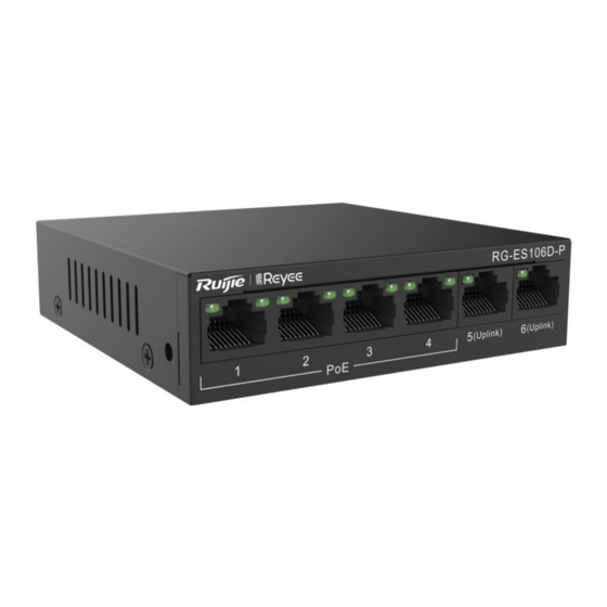
Hardware Installation and Reference Guide Overview RG-ES106D-P 1.2.1 Package Contents Table 1-1 Package Contents Item Quantity RG-ES106D-P Host Power Adapter Power Cord Quick Start Guide Warranty Card Instruction The preceding table lists items delivered in normal cases. The actually delivered items may vary with the contract. - Page 7 Hardware Installation and Reference Guide Overview Figure 1-2 Front Panel of RG-ES106D-P Item Description Copper port status indicator. The statuses are as follows: Solid green: The port is connected at 10/100 Mbps. Copper port status indicator Blinking green: The port is receiving or sending traffic at 10/100 Mbps.
-
Page 8: Technical Specifications
Hardware Installation and Reference Guide Overview Item Description Port mode Support switchover in three modes: switch-over button Left:Flow Control On Middle: Flow Control Off Right: Port Isolation. When this mode is enabled, ports 1-4 are isolated from each other, but can communicate with ports 5-6. System status System status indicator. - Page 9 Hardware Installation and Reference Guide Overview Storage -40° C to 70° C(-40° F to 158° F) Temperature Operating 10% to 90% RH (non-condensing) Humidity Storage Humidity 5% to 95% RH (non-condensing) Support switchover in three modes: Flow Control On Port Mode Flow Control Off Port Isolation.
- Page 10 Hardware Installation and Reference Guide Overview 1.2.6 Heat Dissipation Solution The RG-ES106D-Padopts natural heat dissipation, thereby ensuring normal function of the device. Maintain a minimum clearance of 100 mm (3.94 in.) around the device. It is recommended to clean the device once every 3 months to avoid dust from blocking vents.
- Page 11 Hardware Installation and Reference Guide Overview 1.3.3 Ports - Front Panel Figure 1-5 shows the front panel of an RG-ES110D-P switch. For the detailed meanings of numbers 1 to 5, see the following table. Figure 1-5 Front Panel of RG-ES110D-P Item Description System...
- Page 12 Hardware Installation and Reference Guide Overview Figure 1-6 Back Panel of RG-ES110D-P Item Description Grounding pole Used to fasten the ground cable. Port mode Support switchover in three modes: switch-over button Left: Flow Control On Middle: Flow Control Off Right: Port Isolation. When this mode is enabled, ports 1-8 are isolated from each other, but can communicate with ports 9 and 10.
- Page 13 Hardware Installation and Reference Guide Overview Port1-8:Supported Port9-10:Not Supported Support PoE and PoE+. Ports 1-8 are PoE/PoE+-capable with the maximum power output of 30W per port. Ports 9-10 do not support PoE or PoE+. The overall maximum output power of PoE/PoE+ is 110W. Less than 8W with no PoE load Power Consumption...
- Page 14 Hardware Installation and Reference Guide Overview Earth Leakage ≤1.5mA Current Dimensions 190 mm x 100 mm x 28 mm (7.48 in. x 3.94 in. x 1.1 in.) (W x D x H) Weight 1.3 kg (2.87 lbs) (With Package) Caution ●...
- Page 15 Hardware Installation and Reference Guide Overview 1.4.2 Product Appearance RG-ES110GDS-P provides 8 10/100/1000Base-T auto-sensing Ethernet ports, 2 1000Base-X SFP ports, a port mode switch-over button and LED indicators on the front panel, and a power socket and a grounding pole on the back panel.
- Page 16 Hardware Installation and Reference Guide Overview Item Description RJ-45 port status: Solid green: The port is connected at 10/100 Mbps. ○ Blinking green: The port is receiving or sending traffic at ○ 10/100 Mbps. Off: The port is not connected. ○...
- Page 17 Hardware Installation and Reference Guide Overview Figure 1-9 Back Panel of RG-ES110GDS-P Item Description Grounding pole Used to fasten the ground cable. AC power port Connect to AC power cables 1.4.5 Technical Specifications Table 1-6 Technical Specifications of an RG-ES110GDS-P Switch Model RG-ES110GDS-P 8 10/100/1000Base-T auto-sensing Ethernet ports (Auto MDI/MDIX), and support...
- Page 18 Hardware Installation and Reference Guide Overview Operating 10% to 90% RH (non-condensing) Humidity Storage Humidity 5% to 95% RH (non-condensing) Support switchover in three modes: Flow Control On Port Mode Flow Control Off Port Isolation. When this mode is enabled, ports 1-8 are isolated from each other, but can communicate with ports 9 and 10.
- Page 19 Hardware Installation and Reference Guide Overview 1.4.6 Heat Dissipation Solution The RG-ES110GDS-P adopts natural heat dissipation, thereby ensuring normal function of the device. Maintain a minimum clearance of 100 mm (3.94 in.) around the device. It is recommended to clean the device once every 3 months to avoid dust from blocking vents.
- Page 20 Hardware Installation and Reference Guide Overview 1.5.3 Ports - Front Panel Figure 1-11 shows the front panel of an RG-ES116G switch. For the detailed meanings of numbers 1 to 4, see the following table. Figure 1-11 Front Panel of RG-ES116G...
- Page 21 Hardware Installation and Reference Guide Overview Item Description System status indicator System status indicator. The statuses are as follows: Solid green: The system is operational. Off: The switch is powered off. RJ-45 port status indicator. The statuses are as follows: Solid orange: The port is connected at 10/100 Mbps.
- Page 22 Hardware Installation and Reference Guide Overview Figure 1-12 Back Panel of RG-ES116G Item Description Grounding pole Used to fasten the ground cable. AC power port Connect to AC power cables 1.5.5 Technical Specifications Table 1-8 Technical Specifications of an RG-ES116G Switch Model RG-ES116G Ports...
- Page 23 Hardware Installation and Reference Guide Overview Storage Humidity 5% to 95% RH (non-condensing) Support switchover in four modes: Flow Control On Flow Control Off Port Isolation. When this mode is enabled, ports 1-14 are isolated from each Port Mode other, and can communicate with ports 15-16. Extend DataTransmission-10Mbps.
- Page 24 Hardware Installation and Reference Guide Overview 1.5.6 Heat Dissipation Solution The RG-ES116Gadopts natural heat dissipation, thereby ensuring normal function of the device. Maintain a minimum clearance of 100 mm (3.94 in.) around the device. It is recommended to clean the device once every 3 months to avoid dust from blocking vents.
- Page 25 Hardware Installation and Reference Guide Overview 1.6.3 Ports - Front Panel Figure 1-14 shows the front panel of an RG-ES124GD switch. For the detailed meanings of numbers 1 to 4, see the following table. Figure 1-14 Front Panel of RG-ES124GD...
- Page 26 Hardware Installation and Reference Guide Overview Item Description System status indicator System status indicator. The statuses are as follows: Solid green: The system is operational. Off: The switch is powered off. RJ-45 port status indicator. The statuses are as follows: Solid orange: The port is connected at 10/100 Mbps.
- Page 27 Hardware Installation and Reference Guide Overview Figure 1-15 Back Panel of RG-ES124GD Item Description Grounding pole Used to fasten the ground cable. AC power port Connect to AC power cables 1.6.5 Technical Specifications Table 1-10 Technical Specifications of an RG-ES124GD Switch Model RG-ES124GD Ports...
- Page 28 Hardware Installation and Reference Guide Overview Storage Humidity 5% to 95% RH (non-condensing) Support switchover in four modes: Flow Control On Flow Control Off Port Isolation. When this mode is enabled, ports 1-22 are isolated from each Port Mode other, and can communicate with ports 23-24. Extend DataTransmission-10Mbps.
- Page 29 Hardware Installation and Reference Guide Overview 1.6.6 Heat Dissipation Solution The RG-ES124GDadopts natural heat dissipation, thereby ensuring normal function of the device. Maintain a minimum clearance of 100 mm (3.94 in.) around the device. It is recommended to clean the device once every 3 months to avoid dust from blocking vents.
- Page 30 Hardware Installation and Reference Guide Overview Figure 1-16 Appearance of RG-ES118S-LP 1.7.3 Ports - Front Panel Figure 1-17 shows the front panel of an RG-ES118S-LP switch. For the detailed meanings of numbers 1 to 6, see the following table. Figure 1-17 Front Panel of RG-ES118S-LP Item Description...
- Page 31 Hardware Installation and Reference Guide Overview Item Description RJ-45 port status: Solid green: The port is connected at 10/100 Mbps. ○ Blinking green: The port is receiving or sending traffic at ○ 10/100 Mbps. Off: The port is not connected. ○...
- Page 32 Hardware Installation and Reference Guide Overview Figure 1-18 Back Panel of RG-ES118S-LP Item Description Grounding pole Used to fasten the ground cable. AC power port Connect to AC power cables 1.7.5 Technical Specifications Table 1-12 Technical Specifications of an RG-ES118S-LP Switch Model RG-ES118S-LP 16 10/100Base-TX auto-sensing Ethernet ports (Auto MDI/MDIX), and support...
- Page 33 Hardware Installation and Reference Guide Overview Operating 0° C to 45° C(32° F to 113° F) Temperature Storage -40° C to 70° C(-40° F to 158° F) Temperature Operating 10% to 90% RH (non-condensing) Humidity Storage Humidity 5% to 95% RH (non-condensing) Support switchover in three modes: Flow Control On Port Mode...
- Page 34 Hardware Installation and Reference Guide Overview ● It is not recommended to deploy RG-ES118S-LP switch in places where children may appear. 1.7.6 Heat Dissipation Solution The RG-ES118S-LP adopts fans for heat dissipation, thereby ensuring normal function of the device in the specified environment.
- Page 35 Hardware Installation and Reference Guide Overview Figure 1-19 Appearance of RG-ES118GS-P 1.8.3 Ports - Front Panel Figure 1-20 shows the front panel of an RG-ES118GS-P switch. For the detailed meanings of numbers 1 to 6, see the following table. Figure 1-20 Front Panel of RG-ES118GS-P Item Description...
- Page 36 Hardware Installation and Reference Guide Overview Item Description RJ-45 port status: Solid green: The port is connected at 10/100/1000 Mbps. ○ Blinking green: The port is receiving or sending traffic at ○ 10/100/1000 Mbps. Off: The port is not connected. ○...
- Page 37 Hardware Installation and Reference Guide Overview Figure 1-21 Back Panel of RG-ES118GS-P Item Description Grounding pole Used to fasten the ground cable. AC power port Connect to AC power cables 1.8.5 Technical Specifications Table 1-14 Technical Specifications of an RG-ES118GS-P Switch Model RG-ES118GS-P 16 10/100/1000Base-T auto-sensing Ethernet ports (Auto MDI/MDIX), and support...
- Page 38 Hardware Installation and Reference Guide Overview Operating 10% to 90% RH (non-condensing) Humidity Storage Humidity 5% to 95% RH (non-condensing) Support switchover in three modes: Flow Control On Port Mode Flow Control Off Port Isolation. When this mode is enabled, ports 1-16 are isolated from each other, but can communicate with ports 17 and 18.
- Page 39 Hardware Installation and Reference Guide Overview 1.8.6 Heat Dissipation Solution The RG-ES118GS-P adopts fans for heat dissipation, thereby ensuring normal function of the device in the specified environment. 10 cm distance space should be reserved at both sides and the back plane of the cabinet to allow air circulation.
- Page 40 Hardware Installation and Reference Guide Overview Figure 1-22 Appearance of RG-ES126S-LP 1.9.3 Ports - Front Panel Figure 1-23 shows the front panel of an RG-ES126S-LP switch. For the detailed meanings of numbers 1 to 8, see the following table. Figure 1-23 Front Panel of RG-ES126S-LP Item Description...
- Page 41 Hardware Installation and Reference Guide Overview Item Description Port mode switch-over button Support switchover in three modes: Flow Control On Flow Control Off Port Isolation. When this mode is enabled, ports 1-24 are isolated from each other, but can communicate with ports 25, 26 and 26F. RJ-45 10/100Base-TX 10/100Base-TX adaptive Ethernet portthat supports PoE power supply.
- Page 42 Hardware Installation and Reference Guide Overview Ports 1-24 are 10/100Base-TX auto-sensing Ethernet ports, and support PoE/PoE+ Ports 25 and 26 are 10/100/1000Base-T auto-sensing Ethernet ports, and do not Ports support PoE/PoE+ Port 26F is a 1000Base-X SFP port multiplexed with Port 26 as a combo port, and the SFP port takes priority AC input: Rated voltage range: 100 VAC to 240 VAC...
-
Page 43: Transceiver Modules
1.10 Transceiver Modules Based on the port types, Ruijie provides corresponding SFP modules (Mini-GBIC modules) and 10G SFP+ modules. You can select modules based on usage requirements. In addition to the following modules, the O/E conversion 1000M SFP module (Mini-GBIC-GT) is supported. This document provides models and technical parameters of some 1000M SFP modules and 10G SFP+ modules for reference. - Page 44 Hardware Installation and Reference Guide Overview 1.10.1 1000M SFP Transceiver Modules Table 1-17 1000M SFP Transceiver Module Technical Specifications Support TX Power RX Power (dBm) Digital (dBm) Diagnostic Wavelength Fiber Model Monitoring (nm) Type (DDM) (Yes/No) Multi-m –9.5 –3 –17 MINI-GBIC-SX-MM850 Single- –9.5...
- Page 45 Hardware Installation and Reference Guide Overview Support TX Power RX Power (dBm) Digital (dBm) Diagnostic Wavelength Fiber Model Monitoring (nm) Type (DDM) (Yes/No) Single- –9 –3 –20 –3 GE-LX-SM1310 1310 mode Single- –9 –3 –20 –3 SFP-S4-R1000P1 v1 1310 mode Table 1-18 1000M SFP Transceiver Module Technical Specifications Standard...
- Page 46 Hardware Installation and Reference Guide Overview Maximum Core Specifications SFP Model Port Type Fiber Type Cabling (μm) Distance SFP-SM1310 Single-mode 9/125 10 km GE-SFP-ZX Multi-mode 50/125 550 m GE-SX-MM850 Multi-mode 50/125 550 m GE-LX-SM1310 Single-mode 9/125 10 km SFP-S4-R1000P1 v1 Single-mode 9/125 10 km...
-
Page 47: Sfp+ Transceiver Modules
Hardware Installation and Reference Guide Overview Rate/Distance PairingModel GE-SFP-LH40-SM1310-BIDI 1000M/40 km GE-SFP-LH40-SM1550-BIDI XG-SFP-LR-SM1270-BIDI 10G/10 km XG-SFP-LR-SM1330-BIDI Instruction ● The BIDI transceiver modules at both ends must be paired for use. For example, if GE-SFP-LX20-SM1310-BIDI is used at one end, GE-SFP-LX20-SM1550-BIDI must be used at the other end. - Page 48 ● Types/models of SFP+ series modules are being updated. To obtain more accurate module models, contact Ruijie's marketing personnel or technical support personnel. ● The DDM function of the active optical cables (AOCs) does not have TX power report. The TX power can be displayed as N/A.
-
Page 49: Ethernet Cables
Hardware Installation and Reference Guide Overview Table 1-23 SFP+ Module Cabling Specifications Core Modal Maximum Port Specifications Bandwidth Model Fiber Type Cabling Type Distance (μm) (MHz km) XG-SFP-SR-MM850 Multi-mode 50/125 2000 (OM3) 300 m XG-SR-MM850 Multi-mode 50/125 2000 (OM3) 300 m SFP+MM850 Multi-mode 50/125... -
Page 50: Optical Fibers
Hardware Installation and Reference Guide Overview Instruction For details about the connection methods and signals of twisted-pair cables, seeConnection Modes of Cables Prepared by Users. 1.11.2 Optical Fibers Table 1-24 Features of Optional Transmission Media Model Description Wavelength: 850 nm The maximum transmission distance of a 62.5/125 μm multi-mode optical fiber is 220 1000BASE-SX The maximum transmission distance of a 50/125 μm multi-mode optical fiber is 500... - Page 51 Hardware Installation and Reference Guide Overview Table 1-25 SFP+ Transmission Media and Distance Specifications XG-SFP-SR-MM850 XG-SFP-LR-SM1310 XG-SFP-ER-SM1550 XG-SFP-ZR-SM1550 Wavelength 1310 1550 1550 (nm) Multi-mode optical Single-mode optical Single-mode optical Single-mode optical Fiber Type fiber-LC connector fiber-LC connector fiber-LC connector fiber-LC connector Core Specifications 62.5/125...
-
Page 52: Preparing For Installation
Hardware Installation and Reference Guide Preparing for Installation Preparing for Installation Safety Precautions Instruction ● To avoid personal injury and device damage, carefully read the safety precautions before you install the switch. ● The following safety precautions may not cover all possible dangers. 2.1.1 General Safety Precautions ⚫... -
Page 53: Electrostatic Discharge Safety
Hardware Installation and Reference Guide Preparing for Installation ⚫ Check the switch carefully before shutting down the power supply. ⚫ If a power supply system is equipped with a leakage protector (also referred to as "leakage current switch" or "leakage current breaker"), the rated leakage action current of each leakage protector is greater than twice of the theoretical maximum leakage current of all the power supplies in the system. -
Page 54: Installation Environment Requirements
2.2.4 Temperature/Humidity Requirements To ensure the normal operation and prolonged service life of the RG-ES1 series switches, maintain an appropriate temperature and humidity in the equipment room. The equipment room with too high or too low temperature and humidity for a long period may damage the switch. -
Page 55: Cleanliness Requirements
Hardware Installation and Reference Guide Preparing for Installation 2.2.5 Cleanliness Requirements Dust poses a major threat to the switch. The indoor dust takes on a positive or negative static electric charge when falling on the switch, causing poor contact of the metallic joint. Such electrostatic adhesion may occur more easily when the relative humidity is low, not only affecting the service life of the switch, but also causing communication faults. -
Page 56: Anti-Interference Requirements
Take electromagnetic shielding measures when necessary. 2.2.8 Lightning Protection Requirements The RG-ES1 series switches can guard against lightning strikes. As an electric device, it may still be damaged by strong lightning strikes. Take the following lightning protection measures: ⚫ Ensure that the ground cable of the cabinet is in good contact with the ground. -
Page 57: Cabinet Installation Requirements
Hardware Installation and Reference Guide Preparing for Installation switch can be horizontally placed on a clean plane if conditions are not met. It is recommended to install air conditioners if you want to use the switch in hot areas. ⚫ The cabinet and workbench has proper ventilation and heat dissipation. - Page 58 Antistatic gloves or Antistatic wrist strap, wire stripper, crimping pliers, crystal connector Special Tools crimping pliers, and wire cutter Meter Multimeter Relevant PC, display, and keyboard Devices Instruction The RG-ES1 series switches are delivered without a tool kit. Please prepare a tool kit yourself.
-
Page 59: Installing The Switch
Hardware Installation and Reference Guide Installing the Switch Installing the Switch Ensure that requirements in Chapter 2 are all met. Installation Procedure Prepare for Installation Install the cabinet Mount the switch into the cabinet Ground the switch Connect the power supply Insert various modules Connect cables or fibers of various modules... -
Page 60: Mounting The Switch
Hardware Installation and Reference Guide Installing the Switch Preparing The RG-ES1 series switch is a complex device. Carefully plan and arrange the installation position, networking mode, power supply, and cabling before installation. Confirm the following requirements before installation: ⚫ The installation position provides sufficient space for heat dissipation. - Page 61 Hardware Installation and Reference Guide Installing the Switch seams no more than 1.5 cm (0.59 in.) in diameter to prevent rodents and other small animals from entering the cabinet. ⚫ Antistatic wrist straps should be provided in the cabinet. Simple Installation Steps for Cabinet (1) Plan the available space before installing the cabinet.
- Page 62 Hardware Installation and Reference Guide Installing the Switch Figure 3-2 Attaching the Mounting Bracket to RG-ES116G/RG-ES124GD/RG-ES110GDS-P (2) Use the supplied screws and cage nuts to securely attach the mounting brackets to the cabinet, as shown in Figure 3-3. Figure 3-3 Attaching the Brackets to the Rack...
-
Page 63: Mounting The Switch On The Wall
Hardware Installation and Reference Guide Installing the Switch 3.3.2 Mounting the Switch on the Wall RG-ES106D-Pand RG-ES110D-P can be mounted on the wall. (Mounting screws and wall anchors are customer supplied.) In actual installation, users need to determine the size and depth of the two mounting holes on the wall based on the sizes of wall anchors and screws. -
Page 64: Mounting The Switch On A Workbench
Hardware Installation and Reference Guide Installing the Switch Figure 3-4 Mounting the Switch on the Wall Note Suitable for mounting on concrete or other non-combustible surface only. 3.3.3 Mounting the Switch on a Workbench When mounting the switch onto a workbench, note the following: ⚫... -
Page 65: Installing And Removing The Power Supply
Hardware Installation and Reference Guide Installing the Switch Note The device must be installed and operated in the place that can restrict its movement. Installing and Removing the Power Supply 3.4.1 Connecting the Power Cord and Ground Cable Ensure that the power cord and ground cable meet specification requirement. ⚫... -
Page 66: Verifying Installation
Hardware Installation and Reference Guide Installing the Switch ● During the device installation, always make the ground cable connected first and disconnected last. ● The cross-sectional area of the protection ground cable should be at least 2.5 mm2 (12 AWG). 3.4.2 Removing the Power Cord and Ground Cable (1) Open the circuit breaker of the power supply. - Page 67 Hardware Installation and Reference Guide Installing the Switch Adding Unmanaged Device in Topology Premise: There must be devices that can be managed in the network, including Reyee EG or ES2/NBS Switch Adding scenarios: ⚫ Select up link device, scan the QR code or manually add the unmanaged device into the topology. ⚫...
- Page 68 Hardware Installation and Reference Guide Installing the Switch (3) The device is automatically added by scanning the QR code. Select the upper link port from the list. Then the device is added successfully. 3.6.2 Manually Select Unmanaged Device Model (1) Click‘Topology’into the topology page.
- Page 69 Hardware Installation and Reference Guide Installing the Switch (2) Click ‘Topology’ bottom to edit and click on saved devices. To add anunmanageddownlink switch, select ‘Manually add’. (3) Select the corresponding model from the list and the upper link port. Then the device is added successfully.
-
Page 70: System Debugging
Hardware Installation and Reference Guide System Debugging System Debugging Startup Check 4.1.1 Checking Environment Before Power-on (1) Check whether the switch is properly grounded. (2) Check whether the power cord is properly connected. (3) Check whether the power supply voltage meets the requirement. (4) Check whether the network cable is properly connected, whether the terminal (may be PC) is started, and whether configuration parameters are configured. -
Page 71: Maintenance And Troubleshooting
Hardware Installation and Reference Guide Maintenance and Troubleshooting Maintenance and Troubleshooting General Troubleshooting Procedure Troubleshooting Common Faults Symptom Possible Causes Solution The power module does not The status indicator Check whether the power socket at the work. is not on after the equipment room is normal and whether The power cable is in loose the power cable is plugged in. - Page 72 Hardware Installation and Reference Guide Maintenance and Troubleshooting Symptom Possible Causes Solution The Rx and Tx ends are Switch the Rx and Tx ends of the optical connected reversely. fiber. The interconnected optical Replace the optical module with one of module type does not match.
- Page 73 Hardware Installation and Reference Guide Appendix Appendix Connection Modes of Cables Prepared by Users The following describes the connection modes and signals of cables prepared by users. When you hold the RJ-45 connector facing yourself, the signal wires from left to right are numbered 1 to 8. Figure 6-1 Cable Connection and Signals Table 6-1...
- Page 74 Hardware Installation and Reference Guide Appendix Figure 6-2 Four Pairs of Twisted-pair Cables Used by a 1000BASE-T Port Straight-Through Cable Crossover Cable Device A Device A Device B Device B Table 6-2 Definition of Pin Signal Concerning the 100BASE-TX/10BASE-T Port MDI Mode MDI-X Mode Output Transmit Data+...
-
Page 75: Lightning Protection
Hardware Installation and Reference Guide Appendix Figure 6-3 Connection Modes of 100BASE-TX/10BASE-T Twisted-pair Cables Straight-Through Cable Crossover Cable Device A Device A Device B Device B Lightning Protection Installing AC Power Arrester (Lightning Protection Power Strip) The AC power port must be connected to an external lightning protection power strip to prevent the switch from being struck by lightning when the AC power cord is introduced from the outdoor and directly connected to the power port of the switch. - Page 76 Hardware Installation and Reference Guide Appendix Note ● The power arrester is not delivered with the switch. Please purchase it based on actual requirements. ● Make sure that the PE terminal of the power arrester is well grounded. ● After the AC power plug of the switch is connected to the socket of the power arrester (lightning protection power strip), the lightning protection function is implemented only if the RUN indicator is green and the ALARM indicator is OFF.
- Page 77 Hardware Installation and Reference Guide Appendix Figure 6-5 Ethernet Port Arrester Installation Network cable for Network cable connected indoor connection to the outdoor Ethernet port arrester (pasted on the switch Switch housing) Ground cable of the arrester Power input Ground terminal of the switch Adapter cable Metal box for...
- Page 78 Appendix Cabling When the RG-ES1 series switches are installed in a standard 19-inch cabinet, secure the cables around the cable management brackets. Top cabling or bottom cabling is adopted according to the actual situation in the equipment room. All transferred cable connectors should be placed at the bottom of the cabinet in an orderly manner instead of outside the cabinet that is easy to touch.
- Page 79 Hardware Installation and Reference Guide Appendix Figure 6-6 Binding Cables (1) Bend Wind ⚫ Cables of different types (such as power cords, signal cables, and ground cables) should be separated in cabling and bundling. Mixed bundling is disallowed. When they are close to each other, it is recommended to adopt crossover cabling.
- Page 80 Hardware Installation and Reference Guide Appendix Figure 6-8 Binding Cables (3) ⚫ Cables not to be assembled or remaining parts of cables should be folded and placed in a proper position of the cabinet or cable trough. The proper position refers to a position that does not affect device running or damage the switch or cable.
- Page 81 Hardware Installation and Reference Guide Appendix ⚫ Do not use self-tapping screws to fasten terminals. ⚫ Power cables of the same type and in the same cabling direction should be bundled up into cable bunches, with cables in cable bunches clean and straight. ⚫...
-
Page 82: Site Selection
Hardware Installation Guide Appendix Site Selection ⚫ The equipment room should be at least 5 km away from heavy pollution sources, such as the smelter works, coal mine, and thermal power plant. The equipment room should be at least 3.7 km away from medium pollution sources, such as the chemical factory, rubber factory, and electroplating factory. - Page 83 Ruijie Networks Co.,Ltd Floor 11,East Wing, Zhongyipengao Plaza, No.29 Fuxing Road, Haidian District, Beijing China...
Need help?
Do you have a question about the RG-ES1 Series and is the answer not in the manual?
Questions and answers