Ruijie Reyee RG-ES100 Series Hardware Installation And Reference Manual
Hide thumbs
Also See for Reyee RG-ES100 Series:
- Hardware installation and reference manual (42 pages)
Table of Contents
Advertisement
Quick Links
Advertisement
Table of Contents

Related Manuals for Ruijie Reyee RG-ES100 Series


Summary of Contents for Ruijie Reyee RG-ES100 Series
- Page 1 Ruijie Reyee RG-ES100 Series Switches Hardware Installation and Reference Guide...
- Page 2 Ruijie Networks reserves all copyrights of this document. Any reproduction, excerption, backup, modification, transmission, translation or commercial use of this document or any portion of this document, in any form or by any means, without the prior written consent of Ruijie Networks is prohibited. Exemption Statement This document is provided “as is”.
- Page 3 It is intended for the users who have some experience in installing and maintaining network hardware. At the same time, it is assumed that the users are already familiar with the related terms and concepts. Obtaining Technical Assistance Ruijie Networks Website: https://www.ruijienetworks.com/ Technical Support Website: https://ruijienetworks.com/support...
-
Page 4: Product Overview
Ruijie RG-ES100 Series Switches Hardware Installation and Reference Guide 1 Product Overview The RG-ES100 series switches include the following models: 10/100/1000Base-T 10/100Base-TX Auto-sensing 1000Base-X SFP Console Model Auto-sensing Ethernet Port Port Port Ethernet Port RG-ES106D-P 6(Ports 1-4 support PoE/PoE+) 24 (Ports 1-24 support PoE/PoE+) 2... - Page 5 Ruijie RG-ES100 Series Switches Hardware Installation and Reference Guide Operating Humidity 10% to 90% RH Storage Humidity 5% to 95% RH Support switchover in three modes: 1. Flow Control On Port Mode 2. Flow Control Off 3. Port Isolation. When this mode is enabled, ports 1-4 are isolated from each other, but can communicate with ports 5-6.
- Page 6 Ruijie RG-ES100 Series Switches Hardware Installation and Reference Guide Front Panel Figure 1-2 Front Panel of RG-ES106D-P Note: 1. Copper port status LED 2. PoE status LED 3. 10/100Base-TX PoE port 4. 10/100Base-TX auto-sensing Ethernet port Back Panel Figure 1-3 Back Panel of RG-ES106D-P Note: 1.
- Page 7 Ruijie RG-ES100 Series Switches Hardware Installation and Reference Guide Panel Identification State Meaning The switch is powered off. System status LED Solid green The switch is operational. The port is not connected. Upper left corner of the Solid green The port is connected at 10/100 Mbps.
- Page 8 Ruijie RG-ES100 Series Switches Hardware Installation and Reference Guide Storage -40℃ to 70℃ (-40° F to 158° F) Temperature Operating Humidity 10% to 90% RH Storage Humidity 5% to 95% RH Support switchover in three modes: 1. Flow Control On 2.
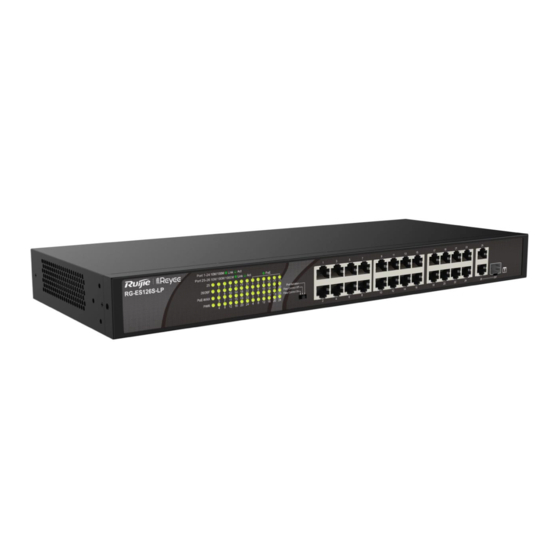
- Page 9 Ruijie RG-ES100 Series Switches Hardware Installation and Reference Guide Front Panel Figure 1-5 Front Panel of RG-ES126S-LP Note: 1. PoE overload LED 6. 10/100Base-TX auto-sensing Ethernet port 2. System status LED 7. 10/100/1000Base-T auto-sensing Ethernet port 3. Port status LED 8.
- Page 10 Ruijie RG-ES100 Series Switches Hardware Installation and Reference Guide The overall PoE output does not reach the maximum power. PoE overload LED PoE-max The overall PoE output reaches the maximum Solid green power. The port is not connected. Link/Act Solid green The port is connected at 10/100/1000 Mbps.
- Page 11 Ruijie RG-ES100 Series Switches Hardware Installation and Reference Guide Storage -40℃ to 70℃ (-40° F to 158° F) Temperature Operating Humidity 10% to 90% RH Storage Humidity 5% to 95% RH Support switchover in three modes: 1. Flow Control On 2.
- Page 12 Ruijie RG-ES100 Series Switches Hardware Installation and Reference Guide Front Panel Figure 1-8 Front Panel of RG-ES110D-P Note: 1. System status LED 2. Port status LED 3. PoE status LED 4. 10/100Base-TX PoE port 5. 10/100/1000Base-T auto-sensing Ethernet port Back Panel...
- Page 13 Ruijie RG-ES100 Series Switches Hardware Installation and Reference Guide Note: 1. Grounding pole 2. Port mode switch-over button 3. DC power socket Heat Dissipation The RG-ES110D-P adopts natural heat dissipation, thereby ensuring normal function of the device. Maintain a minimum clearance of 100 mm (3.94 in.) around the device.
- Page 14 Ruijie RG-ES100 Series Switches Hardware Installation and Reference Guide Frequency: 50/60 Hz Rated current: 2.5 A Port 1-16: Supported Port 17-18: Not Supported Support PoE and PoE+. Ports 1-16 are PoE/PoE+-capable with the maximum power output of 30W per port. Ports 17- 18 do not support PoE or PoE+.
- Page 15 Ruijie RG-ES100 Series Switches Hardware Installation and Reference Guide RG-ES118S-LP provides 16 10/100Base-TX auto-sensing Ethernet ports, 2 1000Base-X SFP combo ports, a port mode switch-over button and LED indicators on the front panel, and a power socket and a grounding pole on the back panel.
- Page 16 Ruijie RG-ES100 Series Switches Hardware Installation and Reference Guide Note: 1. Grounding pole 2. AC power socket Heat Dissipation The RG-ES118S-LP adopts fans for heat dissipation, thereby ensuring normal function of the device in the specified environment. 10 cm distance space should be reserved at both sides and the back plane of the cabinet to allow air circulation.
- Page 17 Ruijie RG-ES100 Series Switches Hardware Installation and Reference Guide 1.5 RG-ES116G Technical Specifications Model RG-ES116G 16 10/100/1000Base-T auto-sensing Ethernet ports Ports AC input Rated voltage range: 100 VAC to 240 VAC Power Supply Maximum voltage range: 90 VAC to 264 VAC Frequency: 50/60 Hz Rated current: 0.5 A...
- Page 18 Ruijie RG-ES100 Series Switches Hardware Installation and Reference Guide Earth Leakage ≤ 1.5mA Current Dimensions 280 mm x 126 mm x 44 mm (11.02 in. x 4.96 in. x 1.73 in.) (W x D x H) Weight 1.75 kg (3.86 lbs) (With Package) The RG-ES116G switch is a class A product.
- Page 19 Ruijie RG-ES100 Series Switches Hardware Installation and Reference Guide Figure 1-12 Back Panel of RG-ES116G Note: 1. Grounding pole 2. AC power port Heat Dissipation The RG-ES116G adopts natural heat dissipation, thereby ensuring normal function of the device. Maintain a minimum clearance of 100 mm (3.94 in.) around the device.
- Page 20 Ruijie RG-ES100 Series Switches Hardware Installation and Reference Guide 1.6 RG-ES124GD Technical Specifications Model RG-ES124GD 24 10/100/1000Base-T auto-sensing Ethernet ports Ports AC input Rated voltage range: 100 VAC to 240 VAC Power Supply Maximum voltage range: 90 VAC to 264 VAC Frequency: 50/60 Hz Rated current: 0.5 A...
- Page 21 Ruijie RG-ES100 Series Switches Hardware Installation and Reference Guide Earth Leakage ≤ 1.5mA Current Dimensions 280 mm x 126 mm x 44 mm (11.02 in. x 4.96 in. x 1.73 in.) (W x D x H) Weight 1.76 kg (3.88 lbs) (With Package) The RG-ES124GD switch is a class A product.
- Page 22 Ruijie RG-ES100 Series Switches Hardware Installation and Reference Guide Figure 1-12 Back Panel of RG-ES124GD Note: 1. Grounding pole 2. AC power socket Heat Dissipation The RG-ES124GD adopts natural heat dissipation, thereby ensuring normal function of the device. Maintain a minimum clearance of 100 mm (3.94 in.) around the device.
-
Page 23: Preparation Before Installation
Ruijie RG-ES100 Series Switches Hardware Installation and Reference Guide 2 Preparation before Installation 2.1 Safety Suggestions To avoid personal injury and equipment damage, please carefully read the safety suggestions before you install the RG-ES100 series switch. The following safety suggestions do not cover all possible dangers. -
Page 24: Static Discharge Damage Prevention
Ruijie RG-ES100 Series Switches Hardware Installation and Reference Guide current of the system totals 30mA. A leakage protector with 30mA rated action current supports less than ten power supplies (that is, Action current of the leakage protector/2/Maximum leakage current of each power supply =30/2/1.5=10). -
Page 25: Temperature And Humidity
Ruijie RG-ES100 Series Switches Hardware Installation and Reference Guide 2.2.1 Ventilation Maintain a minimum clearance of 100 mm (3.94 in.) around the device. After various cables have been connected, they should be arranged into bundles or placed on the cabling rack to avoid blocking the air inlets. It is recommended to clean the switch at regular intervals (like once every 3 months). - Page 26 Ruijie RG-ES100 Series Switches Hardware Installation and Reference Guide Apart from dust, the salt, acid and sulfide in the air in the equipment room must also meet strict requirements, as such poisonous substances may accelerate the corrosion of the metal and the aging of some parts. The equipment room should be protected from the intrusion of harmful gases such as sulfur dioxide, sulfured hydrogen, nitrogen dioxide, and chlorine), whose requirements are listed in Table 2-3.
-
Page 27: Lightning Resistance
Ruijie RG-ES100 Series Switches Hardware Installation and Reference Guide The installation and maintenance personnel must check whether the A.C. socket is well connected to the protection location of the building, if not, they should use a protective grounding wire to connect the grounding end of the A.C. -
Page 28: Installation Tools
Ruijie RG-ES100 Series Switches Hardware Installation and Reference Guide 2.2.7 EMI Electro-Magnetic Interference (EMI), from either outside or inside the equipment or application system, affects the system in the conductive ways such as capacitive coupling, inductive coupling, and electromagnetic radiation. -
Page 29: Product Installation
Ruijie RG-ES100 Series Switches Hardware Installation and Reference Guide 3 Product Installation Please ensure that you have carefully read Chapter 2. 3.1 Installation Flowchart 3.2 Confirmations before Installation Before installation, please confirm the following points: Whether ventilation requirements are met for the switch ... - Page 30 Ruijie RG-ES100 Series Switches Hardware Installation and Reference Guide Ensure that the interface of the power supply cable is well connected to the power interface of the device. The power cables must be protected using power cable retention clips after they are connected to the device.
- Page 31 Ruijie RG-ES100 Series Switches Hardware Installation and Reference Guide Figure 3-3 Attaching the Brackets to the Rack (1) (2)...
-
Page 32: Mounting The Switch On The Wall
Ruijie RG-ES100 Series Switches Hardware Installation and Reference Guide 3.3.2 Mounting the Switch on the Wall RG-ES106D-P and RG-ES110D-P can be mounted on the wall. (Mounting screws and wall anchors are customer supplied.) In actual installation, users need to determine the size and depth of the two mounting holes on the wall based on the sizes of wall anchors and screws. -
Page 33: Checking After Installation
Ruijie RG-ES100 Series Switches Hardware Installation and Reference Guide The device must be installed and operated in the place that can restrict its movement. 3.4 Checking after Installation Before checking the installation, switch off the power supply so as to avoid any personal injury or damage to the component due to connection errors. - Page 34 Ruijie RG-ES100 Series Switches Hardware Installation and Reference Guide Tap the Topology button, and select the existing managed device. To add an unmanaged downlink switch by scanning its QR-code, select Scan to Add. After the device is detected, select its uplink port. And the device is added successfully.
- Page 35 Ruijie RG-ES100 Series Switches Hardware Installation and Reference Guide Tap the Topology button, and select the existing managed device. To add an unmanaged downlink switch manually, select Manually Add. Select the device model and its uplink port, and the device is added successfully.
-
Page 36: System Debugging
Ruijie RG-ES100 Series Switches Hardware Installation and Reference Guide 4 System Debugging 4.1 Startup Check 4.1.1 Checking before the Device is Powered on The switch is fully grounded. The power cable is correctly connected. The power supply voltage complies with the requirement of the switch. -
Page 37: Maintenance And Troubleshooting
Ruijie RG-ES100 Series Switches Hardware Installation and Reference Guide 5 Maintenance and Troubleshooting 5.1 General Troubleshooting Procedure 5.2 Troubleshooting Common Faults Symptom Possible Causes Solution The status indicator is Check whether the power socket at the equipment The power module does not work. -
Page 38: Appendix A Connectors And Connection Media
Ruijie RG-ES100 Series Switches Hardware Installation and Reference Guide Appendix A Connectors and Connection Media 1000BASE-T/100BASE-TX/10BASE-T Ports The 1000BASE-T/100BASE-TX/10BASE-T is a port that supports adaptation of three rates, and automatic MDI/MDIX Crossover at these three rates. The 1000BASE-T complies with IEEE 802.3ab, and uses the cable of 100-ohm Category-5 or Supper Category-5 UTP or STP, which can be up to 100 m. - Page 39 Ruijie RG-ES100 Series Switches Hardware Installation and Reference Guide Optical Fiber Connection For the optical fiber ports, select single-mode or multiple-mode optical fibers for connection according to the fiber module connected. The connection schematic diagram is shown in Figure A-4:...
-
Page 40: Appendix B Lightning Protection
Ruijie RG-ES100 Series Switches Hardware Installation and Reference Guide Appendix B Lightning Protection Installing AC Power Arrester (lightning protection cable row) The external lightning protection cable row shall be used on the AC power port to prevent the switch from being struck by lightning when the AC power cable is introduced from the outdoor and directly connected to the power port of the switch. - Page 41 Ruijie RG-ES100 Series Switches Hardware Installation and Reference Guide During the switch usage, the Ethernet port arrester shall be connected to the switch to prevent the switch damage by lightning before the outdoor network cable connects to the switch. Tools: Cross or straight screwdriver, Multimeter, Diagonal pliers...
- Page 42 Ruijie RG-ES100 Series Switches Hardware Installation and Reference Guide Reversed direction of the arrester installation. You shall connect the external network cable to the “IN” end and connect the switch Ethernet port to the “OUT” end. Poor arrester grounding. The length of the grounding line should be as short as possible to ensure that it is in good contact with the switch grounding terminal.
-
Page 43: Appendix C Cabling Recommendations In Installation
Ruijie RG-ES100 Series Switches Hardware Installation and Reference Guide Appendix C Cabling Recommendations in Installation When RG-ES100 series switches are installed in standard 19-inch cabinets, the cables are tied in the binding rack on the cabinet by the cabling rack, and top cabling or bottom cabling is adopted according to the actual situation in the equipment room. - Page 44 Ruijie RG-ES100 Series Switches Hardware Installation and Reference Guide Cables of different types (such as power cords, signal cables, and grounding cables) should be separated in cabling and bundling. When they are close, crossover cabling can be adopted. In the case of parallel cabling, power cords and signal cables should maintain a space equal to or greater than 30 mm.
- Page 45 Ruijie RG-ES100 Series Switches Hardware Installation and Reference Guide Figure C-3 Bundling Up Cables (3) Cables not to be assembled or remaining parts of cables should be folded and placed in a proper position of the cabinet or cabling slot. The proper position indicates a position that will not affect device running or cause device damage or cable damage during commissioning.
- Page 46 Ruijie RG-ES100 Series Switches Hardware Installation and Reference Guide The hard power cable should be fastened by the terminal connection area to prevent stress. Do not use self-tapping screws to fasten terminals. Power cables of the same type and in the same cabling direction should be bundled up into cable bunches, with cables in cable bunches clean and straight.
-
Page 47: Appendix D Site Selection
Ruijie RG-ES100 Series Switches Hardware Installation and Reference Guide Appendix D Site Selection The machine room should be at least 5km away from the heavy pollution source such as the smelter, coal mine and thermal power plant, 3.7km away from the medium pollution source such as the chemical industry, rubber industry and electroplating industry, and 2km away from the light pollution source such as the food manufacturer and leather plant.
Need help?
Do you have a question about the Reyee RG-ES100 Series and is the answer not in the manual?
Questions and answers