Ruijie Reyee RG-ES1 Series Hardware Installation And Reference Manual
Hide thumbs
Also See for Reyee RG-ES1 Series:
- Hardware installation and reference manual (83 pages) ,
- Hardware installation and reference manual (55 pages) ,
- Cookbook (84 pages)
Table of Contents

Related Manuals for Ruijie Reyee RG-ES1 Series


Summary of Contents for Ruijie Reyee RG-ES1 Series
- Page 1 RG-ES1 Series Switch RG-ES106D-P&RG-ES126S-LP&RG-ES110D-P&RG-ES118S-LP& RG-ES116G&RG-ES124GD&RG-ES110GDS-P&RG-ES118GS-P Hardware Installation and Reference Guide Document Version: V1.5 Date: 2024-03-19 Copyright © 2024 Ruijie Networks...
- Page 2 Ruijie Networks reserves the right to modify the content of the document without any notice or prompt. This manual is designed merely as a user guide. Ruijie Networks has tried its best to ensure the accuracy and reliability of the content when compiling this manual, but it does not guarantee that the content of the manual is completely free of errors or omissions, and all the information in this manual does not constitute any explicit or implicit warranties.
-
Page 3: Preface
Intended Audience This document is intended for: Network engineers Technical support and servicing engineers Network administrators Technical Support The official website of Ruijie Reyee: https://www.ruijienetworks.com/products/reyee Technical Support Website: https://www.ruijienetworks.com/support Case Portal: https://www.ruijienetworks.com/support/caseportal Community: https://community.ruijienetworks.com... - Page 4 This manual presents installation instructions, troubleshooting techniques, technical specifications, cable and connector requirements, and usage guidelines. It is intended for users who want to gain insight into the above content and have some experience in installing and maintaining network hardware. It is assumed that users are already familiar with relevant terms and concepts.
-
Page 5: Table Of Contents
Contents Preface ................................ I Product Overview ..........................1 RG-ES106D-P ........................1 RG-ES126S-LP ........................4 RG-ES110D-P ........................7 RG-ES118S-LP ........................11 RG-ES116G........................14 RG-ES124GD ........................17 RG-ES110GDS-P ....................... 20 RG-ES118GS-P ......................... 23 Preparation Before Installation......................27 Safety Suggestions ......................27 2.1.1 Installation ........................ - Page 6 Troubleshooting Procedure ....................42 Troubleshooting Common Faults ..................42 Appendix A Connectors and Connection Media ..................43 Appendix B Mini-GBIC and SFP Modules ....................45 Appendix C Surge Protection ........................45 Appendix D Cabling Recommendations in Installation ................48 Appendix E Site Selection ........................52...
-
Page 7: Product Overview
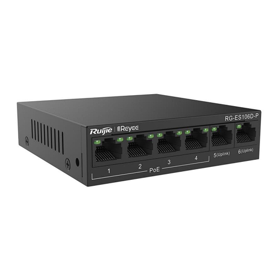
Hardware Installation and Reference Guide Product Overview 1 Product Overview The RG-ES100 series switches include the following models. 10/100/1000Base-T 10/100Base-TX Auto-sensing 1000Base-X SFP Console Model Auto-sensing Ethernet Port Port Port Ethernet Port RG-ES106D-P 6 (ports 1–4 support PoE/PoE+) RG-ES126S-LP 24 (ports 1–24 support PoE/PoE+) 1 (combo) RG-ES110D-P 8 (ports 1–8 support PoE/PoE+) - Page 8 Hardware Installation and Reference Guide Product Overview Operating 0° C to 45° C (32° F to 113° F) Temperature Storage -40° C to +70° C (-40° F to +158° F) Temperature Operating Humidity 10% to 90% RH Storage Humidity 5% to 95% RH Switchover in three modes: 1.
- Page 9 Hardware Installation and Reference Guide Product Overview Note: 1. Electrical port status LED 2. PoE status LED 3. 10/100Base-TX PoE port 4. 10/100Base-TX auto-sensing Ethernet port 5. Nameplate on the bottom of the device Back Panel Figure 1-3 Back Panel of the RG-ES106D-P Note: 1.
-
Page 10: Rg-Es126S-Lp
Hardware Installation and Reference Guide Product Overview Panel Identification State Meaning The switch is powered off. System status LED Solid green The switch is operational. The port is not connected. Solid green The port is connected at a rate of 10/100 Mbps. The port is receiving or sending traffic at a rate of Upper left corner of the Blinking green... - Page 11 Hardware Installation and Reference Guide Product Overview Power Less than 10 W with no PoE load Consumption Less than 220 W with PoE full load Operating 0° C to 45° C (32° F to 113° F) Temperature Storage -40° C to +70° C (-40° F to +158° F) Temperature Operating Humidity 10% to 90% RH...
- Page 12 Hardware Installation and Reference Guide Product Overview Figure 1-5 Front Panel of the RG-ES126S-LP Note: 1. PoE overload LED 6. 10/100Base-TX auto-sensing Ethernet port 2. System status LED 7. 10/100/1000Base-T auto-sensing Ethernet port 3. Port status LED 8. 10/100/1000Base-T combo port 4.
-
Page 13: Rg-Es110D-P
Hardware Installation and Reference Guide Product Overview The overall PoE output does not reach the maximum power. PoE overload LED PoE-max The overall PoE output reaches the maximum Solid green power. The port is not connected. The port is connected at a rate of 10/100/1000 Solid green Mbps. - Page 14 Hardware Installation and Reference Guide Product Overview Ports 1 to 8 support PoE/PoE+ with the maximum power output of 30 W per port. Ports 9–10 do not support PoE or PoE+. The overall maximum output power of PoE/PoE+ is 110 W. Power Less than 8 W with no PoE load Consumption...
- Page 15 Hardware Installation and Reference Guide Product Overview Front Panel Figure 1-8 Front Panel of the RG-ES110D-P Note: 1. System status LED 2. Port status LED 3. PoE status LED 4. 10/100Base-TX PoE port 5. 10/100/1000Base-T auto-sensing Ethernet port 6. Nameplate on the bottom of the device Back Panel Figure 1-9 Back Panel of the RG-ES110D-P...
- Page 16 Hardware Installation and Reference Guide Product Overview Note: 1. Grounding pole 2. Port mode switchover button 3. DC power socket Heat Dissipation The RG-ES110D-P adopts natural heat dissipation, thereby ensuring normal operation. You must maintain a minimum clearance of 100 mm (3.94 in.) around the RG-ES110D-P. It is recommended that you clean the RG-ES110D-P once every three months to avoid dust from blocking vents.
-
Page 17: Rg-Es118S-Lp
Hardware Installation and Reference Guide Product Overview PoE does not supply power. RJ45 PoE status LED PoE (1–8) Solid green PoE is operational. Blinking green PoE is overloaded. 1.4 RG-ES118S-LP Technical Specifications RG-ES118S-LP Model Sixteen 10/100Base-TX auto-sensing Ethernet ports (auto MDI/MDIX), and PoE/PoE+ support Ports Two 1000Base-X SFP combo ports ... - Page 18 Hardware Installation and Reference Guide Product Overview Accessing Optical Not supported Module Information Certification Earth Leakage ≤ 1.5 mA Current Dimensions 440 mm x 208 mm x 44 mm (17.32 in. x 8.19 in. x 1.73 in.) (W x D x H) Weight 3.40 kg (7.50 lbs) (With Package)
- Page 19 Hardware Installation and Reference Guide Product Overview Note: 1. System status LED 4. Port mode switchover button 2. Port status LED 5. 10/100Base-TX auto-sensing Ethernet port 3. PoE status LED 6. 10/100/1000Base-T combo port 7. Nameplate on the bottom of the device Back Panel Figure 1-12 Back Panel of the RG-ES118S-LP Note:...
-
Page 20: Rg-Es116G
Hardware Installation and Reference Guide Product Overview Solid orange A 10/100 Mbps link is established on the port. The port is receiving and sending data at 10/100 Blinking orange Mbps. The port is not connected. Solid orange The port is connected at a rate of 100 Mbps. The port is receiving or sending traffic at a rate of Link/ACT Blinking orange... - Page 21 Hardware Installation and Reference Guide Product Overview Operating Humidity 10% to 90% RH Storage Humidity 5% to 95% RH Switchover in four modes: 1. Flow Control On 2. Flow Control Off 3. Port Isolation Port Mode When port isolation is enabled, ports 1-14 are isolated from each other, but can communicate with ports 15 and 16.
- Page 22 Hardware Installation and Reference Guide Product Overview Figure 1-14 Front Panel of the RG-ES116G Note: 1. System status LED 2. Port status LED 3. Port mode switchover button 4. 10/100/1000Base-T auto-sensing Ethernet port 5. Nameplate on the bottom of the device Back Panel Figure 1-15 Back Panel of the RG-ES116G Note:...
-
Page 23: Rg-Es124Gd
Hardware Installation and Reference Guide Product Overview Panel Identification State Meaning The switch is powered off. System status LED Power Solid green The switch is operational. The port is not connected. Solid orange The port is connected at a rate of 10/100 Mbps. The port is receiving or sending traffic at a rate of Blinking orange RJ45 port status LED... - Page 24 Hardware Installation and Reference Guide Product Overview 2. Flow Control Off 3. Port Isolation When port isolation is enabled, ports 1-22 are isolated from each other, but can communicate with ports 23 and 24. 4. Extend Data Transmission-10Mbps: When this mode is enabled, ports 1–8 have a reduced speed of 10 Mbps, with a transmission distance of up to 250 m.
- Page 25 Hardware Installation and Reference Guide Product Overview Note: 1. System status LED 2. Port status LED 3. Port mode switchover button 4. 10/100/1000Base-T auto-sensing Ethernet port 5. Nameplate on the bottom of the device Back Panel Figure 1-18 Back Panel of the RG-ES124GD Note: 1.
-
Page 26: Rg-Es110Gds-P
Hardware Installation and Reference Guide Product Overview Panel Identification State Meaning The switch is powered off. System status LED Power Solid green The switch is operational. The port is not connected. Solid orange The port is connected at a rate of 10/100 Mbps. The port is receiving or sending traffic at a rate of Blinking orange RJ45 port status LED... - Page 27 Hardware Installation and Reference Guide Product Overview Model RG-ES110GDS-P 3. Port Isolation When port isolation is enabled, ports 1-8 are isolated from each other, but can communicate with ports 9 and 10. Fanless Temperature Warning Not supported Accessing Optical Module Not supported Information Certification...
- Page 28 Hardware Installation and Reference Guide Product Overview Note: 1. System status LED 2. Port status LED 3. PoE status LED 4. Port mode switchover button 5. Nameplate 6. 10/100/1000Base-T auto-sensing Ethernet port 7. 1000BASE-X SFP port Back Panel Figure 1-21 Back Panel of the RG-ES110GDS-P Note: 1.
-
Page 29: Rg-Es118Gs-P
Hardware Installation and Reference Guide Product Overview Panel Identification State Meaning The switch is powered off. System status LED Power Solid green The switch is operational. The port is not connected. Solid orange The port is connected at a rate of 10/100 Mbps. The port is receiving or sending traffic at a rate of Blinking orange RJ45 port status LED... - Page 30 Hardware Installation and Reference Guide Product Overview Model RG-ES118GS-P Maximum voltage range: 90 V AC to 264 V AC Frequency: 50/60 Hz Rated current: 3.5 A Not supported Ports 1 to 16 support PoE/PoE+ Ports 17 and 18 do not support PoE or PoE+ PoE/PoE+ ports 247 W ≤285 W...
- Page 31 Hardware Installation and Reference Guide Product Overview Front Panel Figure 1-23 Front Panel of the RG-ES118GS-P Note: 1. System status LED 2. PoE status LED 3. Port status LED 4. Nameplate 5. Port mode switchover button 6. 10/100/1000Base-T auto-sensing Ethernet port 7.
- Page 32 Hardware Installation and Reference Guide Product Overview Note: 1. Vents 2. Grounding pole 3. AC power socket Heat Dissipation The RG-ES118GS-P adopts fans for heat dissipation, thereby ensuring normal operation. You must reserve 10 cm distance space at both sides and the back plane of the cabinet to allow airflow. It is recommended that you clean the RG-ES126S- LP once every three months to avoid dust from blocking vents.
-
Page 33: Preparation Before Installation
Hardware Installation and Reference Guide Preparation Before Installation Panel Identification State Meaning The port operates at 1000 Mbps and is Blinking green transmitting data. PoE does not supply power. RJ45 PoE status LED PoE (1–16) Solid green PoE is operational. Blinking green PoE is overloaded. -
Page 34: Static Discharge Damage Prevention
Hardware Installation and Reference Guide Preparation Before Installation Before installing the device, find out the location of the emergency power supply switch in the room. First cut off the power supply in the case of an accident. Try to avoid maintaining the switch that is powered on alone. ... -
Page 35: Installation Site Requirements
Hardware Installation and Reference Guide Preparation Before Installation When the optical module is working, do not pull out the fiber cable or look directly into the transceiver. The transceiver emits laser light that may hurt your eyes. Do not stare into any optical port under any circumstances because this may cause permanent damage to your eyes. 2.2 Installation Site Requirements The installation site must meet the following requirement to ensure normal working and a prolonged durable life of the switch. -
Page 36: Cleanness
Hardware Installation and Reference Guide Preparation Before Installation 2.2.3 Cleanness Dust poses a severe threat to the running of the device. The indoor dust falling on the device may be absorbed by the static electricity, causing bad contact of the metallic joint. Such electrostatic absorption may occur more easily when the relative humidity is low. - Page 37 Hardware Installation and Reference Guide Preparation Before Installation Effective grounding of the switch guarantees surge protection and interference resistance. Therefore, connect the grounding line of the switch properly. The grounding cable is prepared by customers. Safety Grounding The device using AC power supply must be grounded by using the yellow/green safety grounding cable. Otherwise, when the insulating resistance decreases the power supply and the enclosure in the equipment, electric shock may occur.
-
Page 38: Lightning Resistance
Hardware Installation and Reference Guide Preparation Before Installation 2.2.6 Lightning Resistance When the AC power cable is imported outdoors and directly connected to the power port of the RG-ES100 series switch, use the lightning line bank to prevent the switch from being hit by lightning shocks. In this case, connect the mains supply AC cable to the lightning line bank, and connect the switch to the lightning line bank. -
Page 39: Product Installation
Hardware Installation and Reference Guide Product Installation 3 Product Installation 3.1 Installation Flowchart 3.2 Precautions Before Installation Before installation, confirm the following points: Check whether ventilation requirements are met for the switch. -
Page 40: Installing The Rg-Es100
Hardware Installation and Reference Guide Product Installation Check whether the requirements of temperature and humidity are met for the switch. Check whether power cables are already laid out and whether the requirements of electrical current are met. Check whether related network adaption lines are already laid out. - Page 41 Hardware Installation and Reference Guide Product Installation Step 2: Use the supplied screws and cage nuts to securely attach the mounting brackets to the rack, as shown in Figure 3-3. Figure 3-3 Attaching the Brackets to the Rack (1)...
-
Page 42: Mounting The Switch Against A Wall
Hardware Installation and Reference Guide Product Installation (2) 3.3.2 Mounting the Switch Against a Wall The RG-ES106D-P and RG-ES110D-P can be mounted against the wall. Mounting screws and wall anchors are customer supplied. You need to determine the size and depth of the two mounting holes on the wall based on the sizes of wall anchors and screws. -
Page 43: Mounting The Switch On A Table
Hardware Installation and Reference Guide Product Installation It is suitable for mounting on the concrete or non-combustible surface only. 3.3.3 Mounting the Switch on a Table The RG-ES110D-P is used as an example. Place the switch on a table, as shown in Figure 3-2. Figure 3-5 Placing the Switch on a Table The device must be installed and operated in the place that can restrict its movement. -
Page 44: Adding An Unmanaged Device To The Topology
Hardware Installation and Reference Guide Product Installation 3.5 Adding an Unmanaged Device to the Topology Note: Devices including Reyee EG or ES2/NBS switches can be managed in the network. Scenarios: To add an unmanaged switch, select its uplink device, and scan the QR Code on the switch or manually add it to the topology. -
Page 45: Adding An Unmanaged Device Manually
Hardware Installation and Reference Guide Product Installation 3.5.2 Adding an Unmanaged Device Manually Tap Topology to access the topology page. Tap the Topology button, and select the existing managed device. To add an unmanaged downstream switch manually, select Manually Add. Select the device model and its uplink port. - Page 46 Hardware Installation and Reference Guide Product Installation...
-
Page 47: System Commissioning
Hardware Installation and Reference Guide System Commissioning 4 System Commissioning 4.1 Startup Check 4.1.1 Checking Before the Device Is Powered On The switch is well grounded. The power cable is correctly connected. The power supply voltage complies with the requirement of the switch. 4.1.2 Checking After Program Startup (Recommended) After power-on, you are advised to perform the following checks to ensure the normal operation of follow-up configurations. -
Page 48: Maintenance And Troubleshooting
Hardware Installation and Reference Guide Maintenance and Troubleshooting 5 Maintenance and Troubleshooting 5.1 Troubleshooting Procedure 5.2 Troubleshooting Common Faults Symptom Possible Causes Solution The status indicator is Check whether the power socket in the equipment The power module does not work. not on after the switch room is normal and whether the power cable is The power cable is in loose contact. -
Page 49: Appendix A Connectors And Connection Media
Hardware Installation and Reference Guide Appendix A Connectors and Connection Media Appendix A Connectors and Connection Media 1000BASE-T/100BASE-TX/10BASE-T Ports The 1000BASE-T/100BASE-TX/10BASE-T supports adaptation of three rates and automatic MDI/MDIX crossover at these three rates. The 1000BASE-T complies with IEEE 802.3ab, and uses the cable of 100-ohm Category-5 or Supper Category-5 UTP or STP, which can be up to 100 m. - Page 50 Hardware Installation and Reference Guide Appendix A Connectors and Connection Media Optical Fiber Connection For the optical fiber ports, select single-mode or multimode optical fibers for connections according to the optical module connected. Figure A-4 shows the connection schematic diagram. Figure A-4 Optical Fiber Connections...
-
Page 51: Appendix B Mini-Gbic And Sfp Modules
Hardware Installation and Reference Guide Appendix B Mini-GBIC and SFP Modules Appendix B Mini-GBIC and SFP Modules We provide GE SFP modules (Mini-GBIC modules) according to the SFP port types. You can select the module to fit your specific needs. The following models and technical specifications of some GE SFP modules are listed for your reference. - Page 52 Hardware Installation and Reference Guide Appendix C Surge Protection The surge protection cable row is fixed on the cabinet, operating table, or the wall in the equipment room using the line buttons and screws. Figure B-1 Schematic Diagram for the Power Arrester The power arrester is not provided and customers have to purchase it.
- Page 53 Hardware Installation and Reference Guide Appendix C Surge Protection Ethernet port arrester to the switch framework. The paste location for the Ethernet port arrester must be as close to the grounding terminal of the switch. Based on the distance of the switch grounding terminal, cut the grounding line for the Ethernet port arrester and firmly tighten the grounding line to the grounding terminal of the switch.
-
Page 54: Appendix D Cabling Recommendations In Installation
Hardware Installation and Reference Guide Appendix D Cabling Recommendations in Installation Appendix D Cabling Recommendations in Installation When RG-ES100 series switches are installed in standard 19-inch cabinets, cables are tied in the binding rack on the cabinet by the cabling rack, and top or bottom cabling is adopted according to the actual situation in the equipment room. All cable connectors should be placed at the bottom of the cabinet in an orderly manner but not outside the cabinet. - Page 55 Hardware Installation and Reference Guide Appendix D Cabling Recommendations in Installation Cables of different types (such as power cords, signal cables, and ground cables) should be separated in cabling and bundling. When they are close, crossover cabling can be adopted. In the case of parallel cabling, maintain a space of at least 30 mm for power cords and signal cables.
- Page 56 Hardware Installation and Reference Guide Appendix D Cabling Recommendations in Installation Cables not to be assembled or remaining parts of cables should be folded and placed in a proper position of the cabinet or cabling slot. The proper position will not affect device running or cause device or cable damage during commissioning.
- Page 57 Hardware Installation and Reference Guide Appendix D Cabling Recommendations in Installation The hard power cable should be fastened by the terminal connection area to prevent stress. Do not use self-tapping screws to fasten terminals. Power cables of the same type in the same cabling direction should be bundled up into cable bunches, with clean and straight cables in cable bunches.
-
Page 58: Appendix E Site Selection
Hardware Installation and Reference Guide Appendix E Site Selection Appendix E Site Selection The equipment room should be at least 5 km away from the heavy pollution source such as the smelter, coal mine, and thermal power plant, 3.7 km away from the medium pollution source such as the chemical industry, rubber industry, and electroplating industry, and 2 km away from the light pollution source such as the food manufacturer and leather plant.
Need help?
Do you have a question about the Reyee RG-ES1 Series and is the answer not in the manual?
Questions and answers